Stay tuned!
1:160 S.M.S. WESPE Armoured Gunboat (1876)
Moderators: MartinJQuinn, JIM BAUMANN, HMAS, Tiny69, Dave Wooley
-
wefalck

- Posts: 2079
- Joined: Wed Sep 28, 2011 12:04 pm
- Location: Paris
- Contact:
Re: 1:160 S.M.S. WESPE Armoured Gunboat (1876)
Thanks, gentlemen! Now, with the boats behind me, I have to clear/clean the workbench and bring the actual model back. There are still a few bits and bobs to install, working inside-out in order not damage flimsy parts, and then have to turn my attention to something I am really afraid of: installing the railings 
Stay tuned!
Stay tuned!
Eberhard
Former chairman Arbeitskreis historischer Schiffbau e.V. (German Association for Shipbuilding History)
--------------------------------------------------------------------------------------------------------------------------------------------------------------------------------------------


Former chairman Arbeitskreis historischer Schiffbau e.V. (German Association for Shipbuilding History)
--------------------------------------------------------------------------------------------------------------------------------------------------------------------------------------------
-
Maarten Sch�nfeld

- Posts: 1835
- Joined: Fri Dec 12, 2008 12:44 pm
- Location: Herk-de-Stad, Belgium
Re: 1:160 S.M.S. WESPE Armoured Gunboat (1876)
I fully agree with you, Marijn!marijn van gils wrote:Beautiful boats! And good job on adjusting the paint!
I'll have to try your technique of making thin chain. It looks much more three-dimensional than PE chain.
As for your note about 3D chain, I think Evert-Jan's exploits are of value to you. Look at his article about 'Ground Tackle Part I' from Jan. 2020
https://ontheslipway.com/?s=anchor+chain
Aside of that, of course there's very fine chain available in copper (not brass, that's too coarse). The only problem are the missing studs, but not all chains need them. For example, chain that is used as a stay wouldn't need the studs.
"I've heard there's a wicked war a-blazing, and the taste of war I know so very well
Even now I see the foreign flag a-raising, their guns on fire as we sail into hell"
Roger Whittaker +9/13/2023
Even now I see the foreign flag a-raising, their guns on fire as we sail into hell"
Roger Whittaker +9/13/2023
-
wefalck
- Posts: 2079
- Joined: Wed Sep 28, 2011 12:04 pm
- Location: Paris
- Contact:
Re: 1:160 S.M.S. WESPE Armoured Gunboat (1876)
Maarten, Marijn was referring to my 'faked' chains for the hoisting strops, not to the anchor-chains. The latter were indeed 3D-printed ones originating in Japan.
Eberhard
Former chairman Arbeitskreis historischer Schiffbau e.V. (German Association for Shipbuilding History)
--------------------------------------------------------------------------------------------------------------------------------------------------------------------------------------------
Former chairman Arbeitskreis historischer Schiffbau e.V. (German Association for Shipbuilding History)
--------------------------------------------------------------------------------------------------------------------------------------------------------------------------------------------
-
wefalck
- Posts: 2079
- Joined: Wed Sep 28, 2011 12:04 pm
- Location: Paris
- Contact:
Re: 1:160 S.M.S. WESPE Armoured Gunboat (1876)
Small bits and pieces
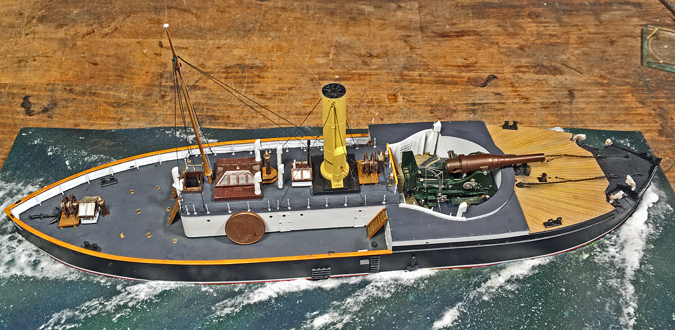
Here are a couple of �family pictures� that show all boats together and with a 1 �-Cent coin for size reference. The jolly-boat also got a bow- and a stern-lanyard added that I had forgot earlier.
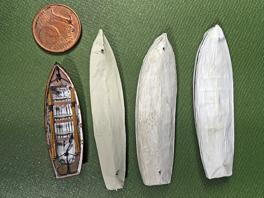
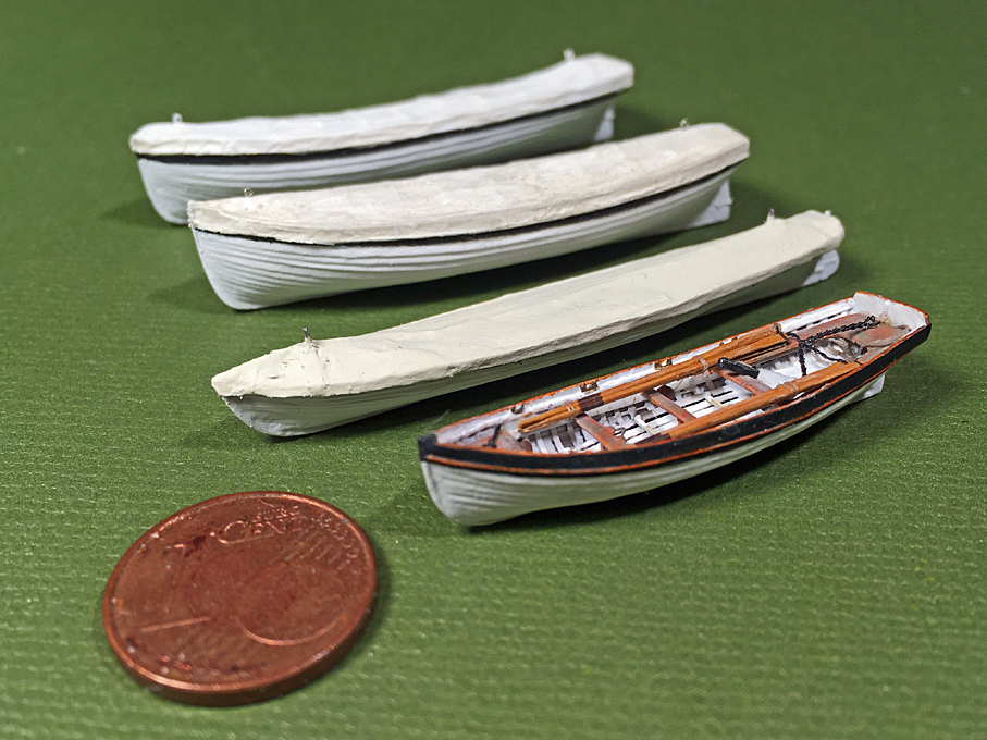
From top to down: 1st cutter, 2nd cutter, gig, and jolly-boat
Now that with the boats the major �sub-models� have been completed. The process of putting everything together continues.
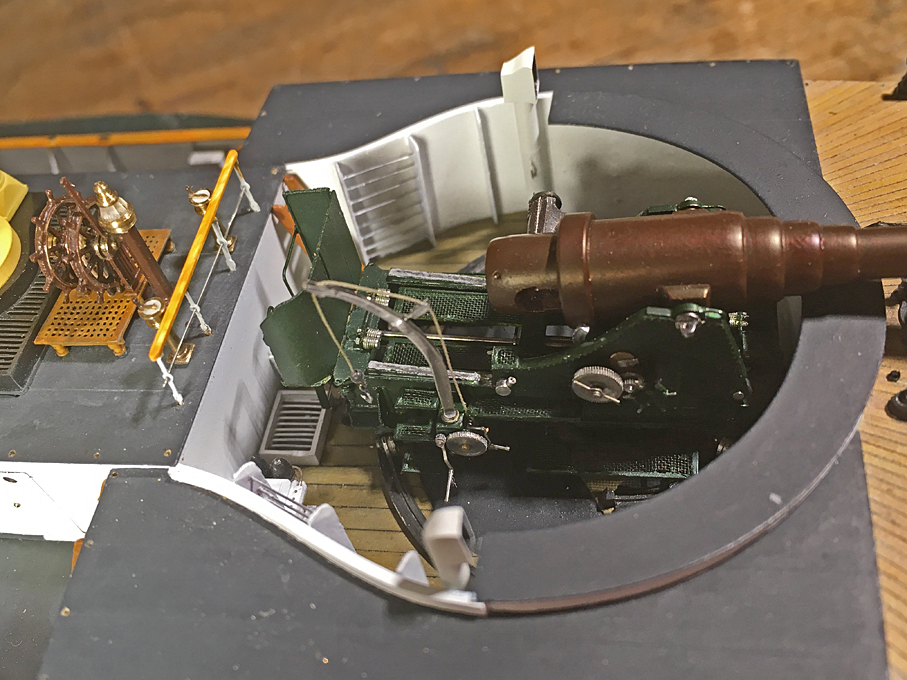
Thus, I have put the gun onto the tracks of the lower carriage. It was just glued in place � something I am not entirely happy with considering the top-weight of the barrel, but hopefully I have added enough white glue at hidden places. The original had clamps that go under the tracks, but this was difficult to reproduce at this scale.
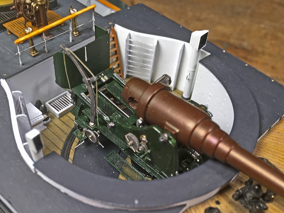
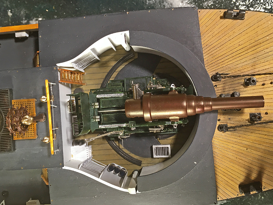
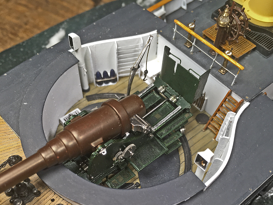
The gun in its emplacement in the barbette
The two engine-room telegraphs were installed on the bridge.
Engine-room telegraphs on the bridge
I am not sure that these were rigged like that, as the existing photographs are either not taken from the right angle or the resolutions is not good enough for the forecastle is too messy. Anyway, two cable stoppers fashioned from �rope� were attached to eyebolts (which were drawn in the plans) and provide additional security against the anchor-chain flying about on the forecastle
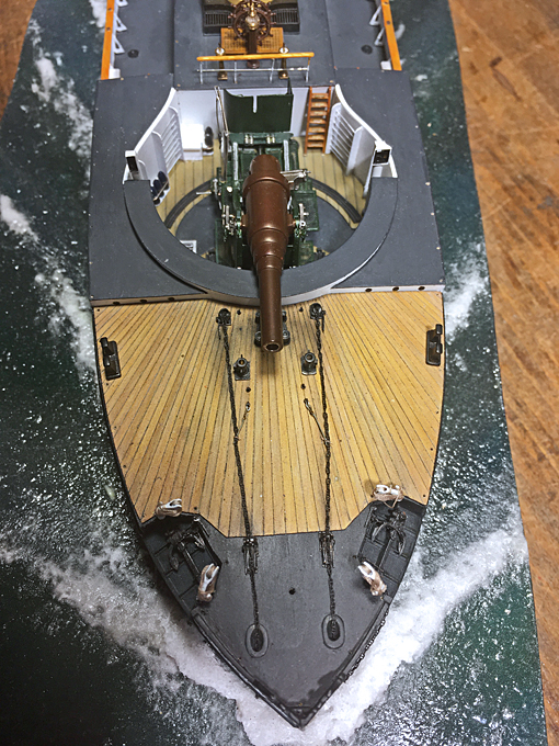
Cable stopper to secure the anchor-chains.
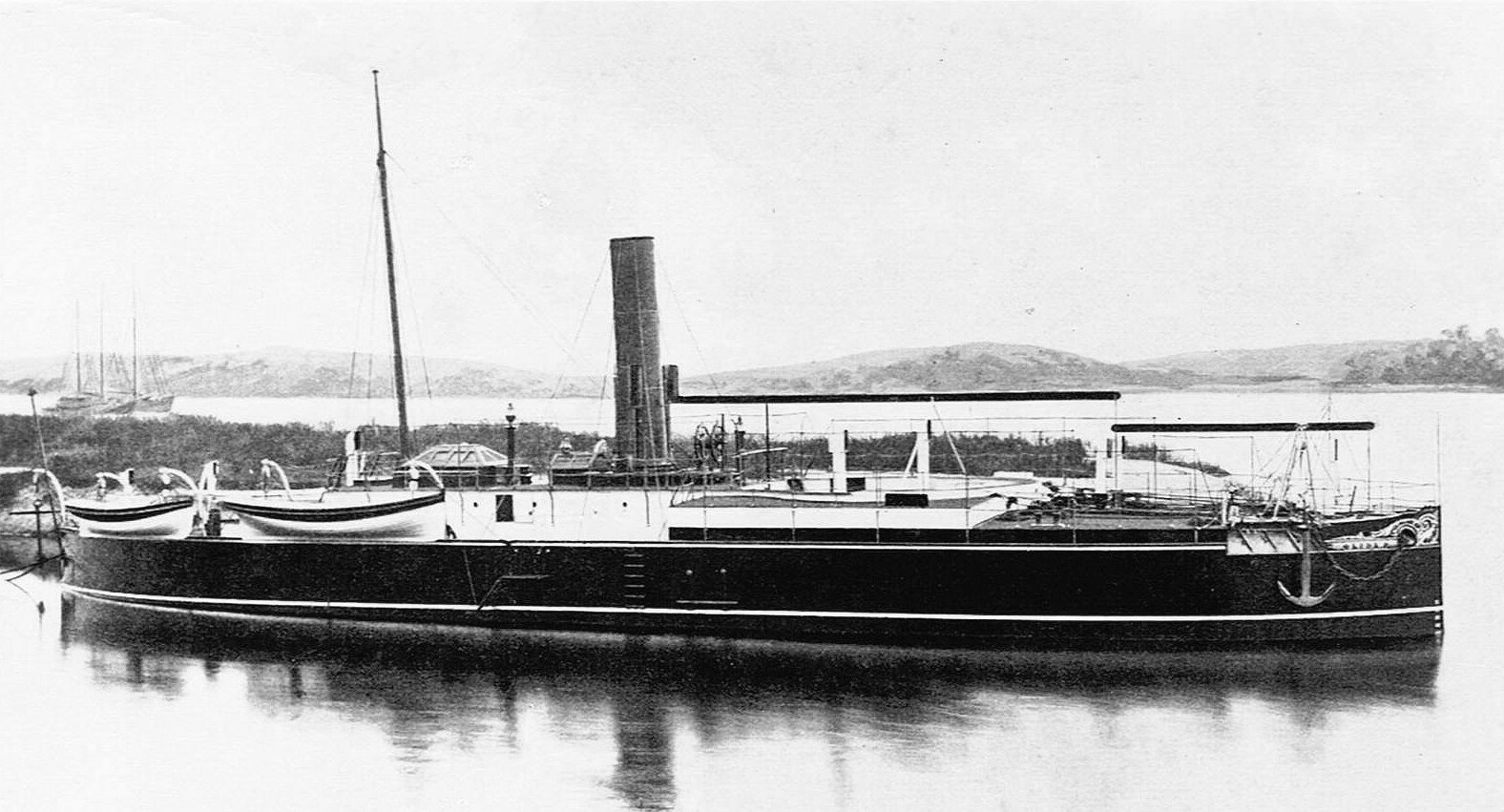
The four anchor cranes were completed with the tackle and temporarily installed. There would have been quite a few metres of the running part to stow securely while on sea. Judging by the photograph of S.M.S. CROCODILL below, it was slung around the cranes in a perhaps not quite so �ship-shape and Bristol-fashion�. Anyway, I emulated this on the model.
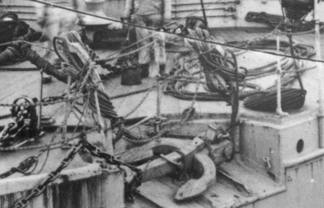
Anchor cranes on S.M.S. CROCODILL later in her life
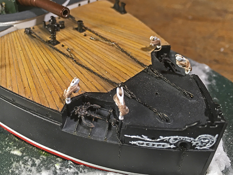
The anchor cranes on the model
Next up is the most dreaded part of the model, the installation of the various chain rails. Because of these I hesitated for a long time to tackle this project.
To be continued ....
Here are a couple of �family pictures� that show all boats together and with a 1 �-Cent coin for size reference. The jolly-boat also got a bow- and a stern-lanyard added that I had forgot earlier.
From top to down: 1st cutter, 2nd cutter, gig, and jolly-boat
Now that with the boats the major �sub-models� have been completed. The process of putting everything together continues.
Thus, I have put the gun onto the tracks of the lower carriage. It was just glued in place � something I am not entirely happy with considering the top-weight of the barrel, but hopefully I have added enough white glue at hidden places. The original had clamps that go under the tracks, but this was difficult to reproduce at this scale.
The gun in its emplacement in the barbette
The two engine-room telegraphs were installed on the bridge.
Engine-room telegraphs on the bridge
I am not sure that these were rigged like that, as the existing photographs are either not taken from the right angle or the resolutions is not good enough for the forecastle is too messy. Anyway, two cable stoppers fashioned from �rope� were attached to eyebolts (which were drawn in the plans) and provide additional security against the anchor-chain flying about on the forecastle
Cable stopper to secure the anchor-chains.
The four anchor cranes were completed with the tackle and temporarily installed. There would have been quite a few metres of the running part to stow securely while on sea. Judging by the photograph of S.M.S. CROCODILL below, it was slung around the cranes in a perhaps not quite so �ship-shape and Bristol-fashion�. Anyway, I emulated this on the model.
Anchor cranes on S.M.S. CROCODILL later in her life
The anchor cranes on the model
Next up is the most dreaded part of the model, the installation of the various chain rails. Because of these I hesitated for a long time to tackle this project.
To be continued ....
Eberhard
Former chairman Arbeitskreis historischer Schiffbau e.V. (German Association for Shipbuilding History)
--------------------------------------------------------------------------------------------------------------------------------------------------------------------------------------------
Former chairman Arbeitskreis historischer Schiffbau e.V. (German Association for Shipbuilding History)
--------------------------------------------------------------------------------------------------------------------------------------------------------------------------------------------
-
DrPR

- Posts: 1689
- Joined: Sun Mar 07, 2010 12:01 am
- Location: Corvallis, Oregon, USA
- Contact:
Re: 1:160 S.M.S. WESPE Armoured Gunboat (1876)
wefalck,
The proximity of the helm station and the gun just dawned on me. It would have been VERY noisy on the bridge when that thing fired!
On the cruiser I was on the ends of the 5"/38 guns were just about 25 feet from the bridge when we were firing back at our quarter. It was an enclosed bridge, and we put our fingers in our ears when we were firing, but I lost all high frequency hearing and gained permanent ringing in my ears (tinnitus) from those guns.
Thanks for posting these pictures. I have been waiting to see that beautiful gun mounted on the ship.
Phil
A collision at sea will ruin your entire day. Aristotle
-
JIM BAUMANN

- Posts: 5678
- Joined: Mon Jan 10, 2005 5:30 pm
- Location: Nr Southampton England
Re: 1:160 S.M.S. WESPE Armoured Gunboat (1876)
Nice looking boat covers!!
The gun is of course sensational-- especially so for its "engineery" feel !
the photo of cluttered foredeck is sobering-
not always tiddly-- but - these were working platforms...
......
The gun is of course sensational-- especially so for its "engineery" feel !
the photo of cluttered foredeck is sobering-
not always tiddly-- but - these were working platforms...
......
....I buy them at three times the speed I build 'em.... will I live long enough to empty my stash...?
http://www.modelshipgallery.com/gallery ... index.html
IPMS UK SIG (special interest group) www.finewaterline.com
http://www.modelshipgallery.com/gallery ... index.html
IPMS UK SIG (special interest group) www.finewaterline.com
-
wefalck
- Posts: 2079
- Joined: Wed Sep 28, 2011 12:04 pm
- Location: Paris
- Contact:
Re: 1:160 S.M.S. WESPE Armoured Gunboat (1876)
Thanks, gentlemen for your kind words!
Well, it's not only the noise from firing the gun, but the officers must have had a lot of confidence in their technology, considering that a gut 42 t (36 t the barrel incl. lock and 6 t the upper carriage) of steel were jumping towards you ...
The picture of the foredeck was taken while the boat was put through the tidal lock of Wilhelmshaven harbour. I don't know which year, but sometime around 1910 I think. The crew would have been busy with the ropes, keeping the boat steady. Later when moored or going to sea, they would have tidied up everything, I would assume.
Eberhard
Former chairman Arbeitskreis historischer Schiffbau e.V. (German Association for Shipbuilding History)
--------------------------------------------------------------------------------------------------------------------------------------------------------------------------------------------
Former chairman Arbeitskreis historischer Schiffbau e.V. (German Association for Shipbuilding History)
--------------------------------------------------------------------------------------------------------------------------------------------------------------------------------------------
-
Iceman 29

- Posts: 1945
- Joined: Tue Sep 29, 2020 4:35 pm
- Location: Bretagne, France
Re: 1:160 S.M.S. WESPE Armoured Gunboat (1876)
It is really a beautiful project extremely well done, the cannon and its barbette are of all beauty.
This barbette when it rained had to become a bathtub...
There had to be a pump system to evacuate the water. Or the barbette was covered with a canvas cover in bad weather?
This barbette when it rained had to become a bathtub...
There had to be a pump system to evacuate the water. Or the barbette was covered with a canvas cover in bad weather?
Pascal
�Battleship Bretagne 3D: https://vu.fr/FvCY
�SS Delphine 3D: https://vu.fr/NeuO
�SS Nomadic 3D: https://vu.fr/tAyL
�USS Nokomis 3D: https://vu.fr/kntC
�USS Pamanset 3D: https://vu.fr/jXGQ
�Battleship Bretagne 3D: https://vu.fr/FvCY
�SS Delphine 3D: https://vu.fr/NeuO
�SS Nomadic 3D: https://vu.fr/tAyL
�USS Nokomis 3D: https://vu.fr/kntC
�USS Pamanset 3D: https://vu.fr/jXGQ
-
wefalck
- Posts: 2079
- Joined: Wed Sep 28, 2011 12:04 pm
- Location: Paris
- Contact:
Re: 1:160 S.M.S. WESPE Armoured Gunboat (1876)
That is indeed an interesting question, particularly as the deck of the barbette is quite close to the CWL.
One can see on the various drawings that there was a manually operated pump that was linked to the same system of cranks by which the spill was operated. Perhaps there was also a steam-operated pump, but no plumbing is drawn.
When not at sea, virtually the whole boat was covered in awnings, which would have kept quite a bit of the rainwater out:

I decided not to install the awning stanchions on the model. They would have been so fragile or easily bent at 0.2 to 0.3 mm diametre, that their installation would have driven me insane. Apart from that, I don't like the look of it too much, even though it would have been probably authentic. I will eventually show the stanchions stowed in racks on the deckhouse, for which there is some pictorial evidence. I also omitted their sockets, I must admit, because I couldn't quite make out what they looked like empty.
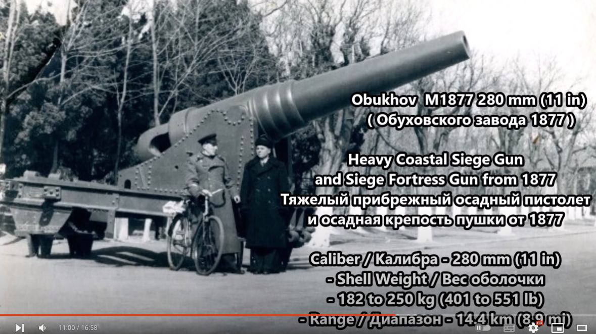
Talking about the gun, there was somewhere on the net film that shows a comparable 28 cm-gun, a Krupp-clone, being fired on a Russian fortress, but I can't put my hand on it right now. It's a silent movie, of course.
One can see on the various drawings that there was a manually operated pump that was linked to the same system of cranks by which the spill was operated. Perhaps there was also a steam-operated pump, but no plumbing is drawn.
When not at sea, virtually the whole boat was covered in awnings, which would have kept quite a bit of the rainwater out:
I decided not to install the awning stanchions on the model. They would have been so fragile or easily bent at 0.2 to 0.3 mm diametre, that their installation would have driven me insane. Apart from that, I don't like the look of it too much, even though it would have been probably authentic. I will eventually show the stanchions stowed in racks on the deckhouse, for which there is some pictorial evidence. I also omitted their sockets, I must admit, because I couldn't quite make out what they looked like empty.
Talking about the gun, there was somewhere on the net film that shows a comparable 28 cm-gun, a Krupp-clone, being fired on a Russian fortress, but I can't put my hand on it right now. It's a silent movie, of course.
Eberhard
Former chairman Arbeitskreis historischer Schiffbau e.V. (German Association for Shipbuilding History)
--------------------------------------------------------------------------------------------------------------------------------------------------------------------------------------------
Former chairman Arbeitskreis historischer Schiffbau e.V. (German Association for Shipbuilding History)
--------------------------------------------------------------------------------------------------------------------------------------------------------------------------------------------
-
Iceman 29
- Posts: 1945
- Joined: Tue Sep 29, 2020 4:35 pm
- Location: Bretagne, France
Re: 1:160 S.M.S. WESPE Armoured Gunboat (1876)
Pascal
�Battleship Bretagne 3D: https://vu.fr/FvCY
�SS Delphine 3D: https://vu.fr/NeuO
�SS Nomadic 3D: https://vu.fr/tAyL
�USS Nokomis 3D: https://vu.fr/kntC
�USS Pamanset 3D: https://vu.fr/jXGQ
�Battleship Bretagne 3D: https://vu.fr/FvCY
�SS Delphine 3D: https://vu.fr/NeuO
�SS Nomadic 3D: https://vu.fr/tAyL
�USS Nokomis 3D: https://vu.fr/kntC
�USS Pamanset 3D: https://vu.fr/jXGQ
-
DrPR
- Posts: 1689
- Joined: Sun Mar 07, 2010 12:01 am
- Location: Corvallis, Oregon, USA
- Contact:
Re: 1:160 S.M.S. WESPE Armoured Gunboat (1876)
I don't recall if you mentioned this before when you were planking the fore deck, but what was the angle between the edges of planks? Were they designed to indicate degrees of rotation of the gun?
If there was relative motion between the target and the gun it would have been possible using geometry and trigonometry to estimate the lead angle for firing the gun if the ship had even a primitive optical range finder. Also, from just observing shell splashes a rough adjustment could be figured. This information could be passed to the gun crew for setting up a shot.
In either case the grout lines between planks could have served as a quick guide for rotating the gun.
Phil
A collision at sea will ruin your entire day. Aristotle
-
wefalck
- Posts: 2079
- Joined: Wed Sep 28, 2011 12:04 pm
- Location: Paris
- Contact:
Re: 1:160 S.M.S. WESPE Armoured Gunboat (1876)
Never thought of the plank-seams as an aid for training the gun, but I have doubts that the foredeck was visible to that extent from the gun-captain's platform. I suppose, the idea was to have the gun-blast more or less parallel to the seams and not across them.
Aiming of the naval guns was a primitive affair until the turn of the century. Of course, they could do the simple trigonometry, but there was no short connection between the chartroom, the bridge and the gun. There was an instruction for this gun, indeed it was the first in the 'modern' series of instructions printed by the Imperial Navy, but so far I have been unable to locate a copy, neither in libraries nor in the State Archives.
There was a simple front-sight and a somewhat more sophisticated one at the front, which could be adjusted for the elevation, the winding, and the lead-angle. There were also tables for the different types of projectiles and charges, which presumably were compiled by Krupp together with the Navy at their extensive proving grounds near Meppen in northern Germany. I may try to make and install a simplified version of the rear-sights and then will show some pictures of what they looked like.
Range-finders did not exist yet in the 1870s, it was all guess work. The classical tactics would have been to fire a shot with the guessed distance and observe where it came down, then to adjust the elevation so that it would be more likely long, if the first shot was short, or vice versa. The third shot then should hit. However, this is would not be feasible on moving ships and they were very cautious in actually firing the gun, as the barrel had only a limited life-time. I forgot the number of shots, but it would not exceed much a couple of hundred. Other variables, such as the temperature and humidty of the powder, air-temperature and -pressure etc. were complete uncontrolled.
Eberhard
Former chairman Arbeitskreis historischer Schiffbau e.V. (German Association for Shipbuilding History)
--------------------------------------------------------------------------------------------------------------------------------------------------------------------------------------------
Former chairman Arbeitskreis historischer Schiffbau e.V. (German Association for Shipbuilding History)
--------------------------------------------------------------------------------------------------------------------------------------------------------------------------------------------
-
marijn van gils
- Posts: 2686
- Joined: Tue Feb 06, 2007 10:24 am
- Location: Belgium
Re: 1:160 S.M.S. WESPE Armoured Gunboat (1876)
Now that is coming together very nicely!
The end is slowly coming in sight...
I'm looking forward to see how you will tackle those chain railings.
The end is slowly coming in sight...
I'm looking forward to see how you will tackle those chain railings.
-
wefalck
- Posts: 2079
- Joined: Wed Sep 28, 2011 12:04 pm
- Location: Paris
- Contact:
Re: 1:160 S.M.S. WESPE Armoured Gunboat (1876)
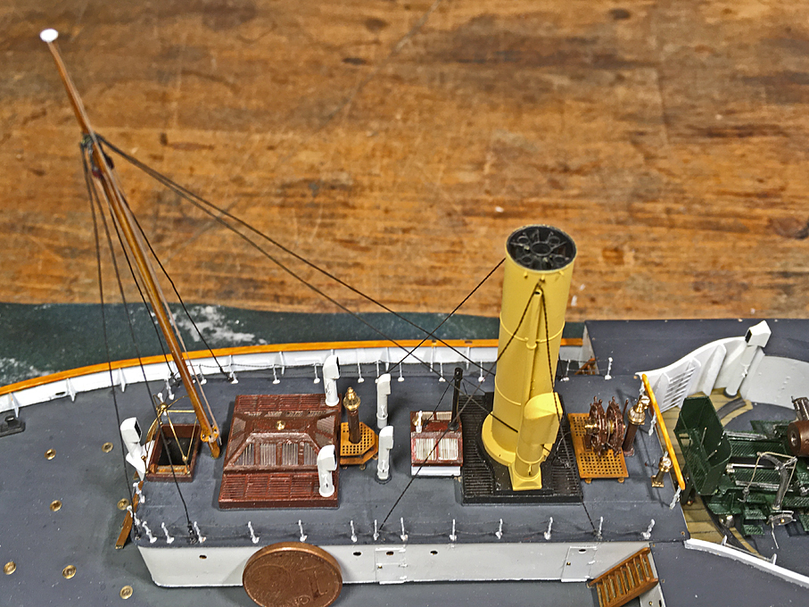
Chain-rails and smoke-stack stays
Due to several business and private travels over the past month not such much progress has been made �
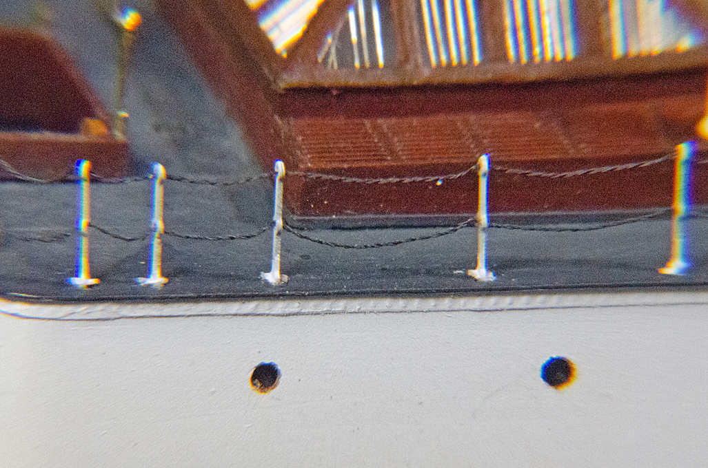
In the meantime, I had received some special material for simulating the various small chains, namely for the railing and the stays for the smoke-stack. The material is black-oxidised Konstantan�-wire of 0.06 mm and 0.07 mm diameter. Konstantan� is a CuNi-alloy that is characterised by a very constant specific resistance over a wide temperature range and low temperature extension coefficient. However, I am not interested in these properties, but it is the thinnest black wire I could get and its breaking strength is somewhat higher than that of pure copper.
The idea is to twist together two strands of wire so that the pitch is approximately that of the length of chain-link. Two strands of this twisted wire then are twisted together in the opposite direction. To the naked eye and with my +3 loupe this looks quite convincingly like a somewhat twisted chain. That is a close as I can get in this scale.
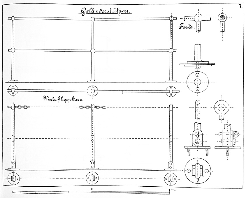
Chain-rail on folding stanchions (from WAAP, 1900).
There is a photograph that shows details of the railing on the deck-house quite clearly and there is an instruction book for draughtsmen (WAAP, 1900) that has a drawing of the folding chain-railing as used by the Imperial German Navy. There is a scale bar that allows to calculate the various dimensions and the height tallies with the railings in the lithographs of the WESPE-Class. According to this the stanchions are around 85 cm heigh which translates to 5.3 mm in 1:160 scale. The chain-links are 60 mm (0.4 mm) long with a wire-diameter of 8 mm (0.05 mm).
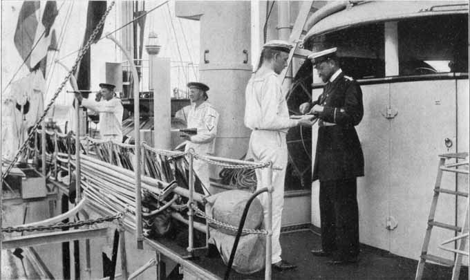
Chain-rail around the deck-house on a WESPE-Class boat (LAVERRENZ, 1900).
Years ago, I had drawn my own stanchions and etched them from 0.2 mm brass-sheet. The idea was to solder two together in order to arrive at the correct thickness, without problems with under-etching in my primitive set-up. However, when I recently saw the commercially produced etched stanchions by S�MANN-�tztechnik in Germany, I realised that my home-made one could not compete quality-wise. However, their two-chain ones in 1:150 were too high (even at that scale). The three-chain ones, on the other hand, where of the correct height when using the lower ring to simulate the hinge for folding down. With the laser-cutter I also cut some small plates to simulate the foot-plates.
The holes for the stanchions were enlarged at the top with a round burr, so that half of the lower ring would be embedded. It would have been nice to have also photoetched parts for the foot-plates, which would have looked much crisper �
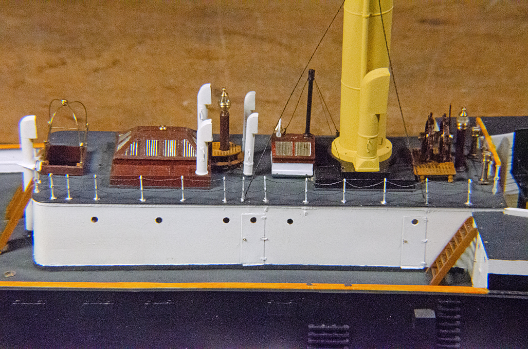
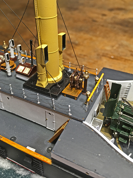
The chain-stays for the smoke-stacks caused me some head-scratching, in particular the connections to the stack and to the deck. The chain was done as for the railings, but with the 0.07 mm wire. Making and fitting shackles of less than 1 mm in length was physically impossible. So, I resorted to some dark grey thread. Not ideal, but there are just some physical limits that are impossible to overcome.
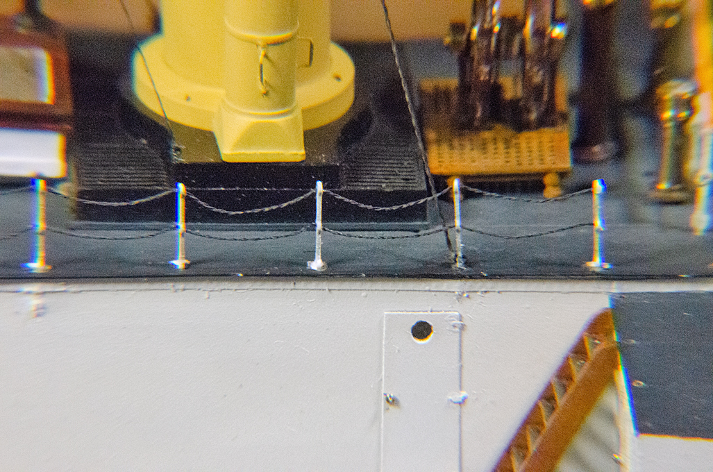
In order to not damage completed work, I am working from the centre of the ship outwards. For this reason, I also had to put on first the inner stays of the smoke-stack and then the railings.
As always, close-up photographs are rather discouraging, but the rails look quite reasonable at normal viewing distance (me thinks).
A problem is the springiness of the wire, so the double-twisted wire is more forgiving than the simple wire. It is not so easy to shape a nice catena that properly sags downwards, with the upper and lower chain in one plane. Luckily, deviations are only noticeable, when looking straight down. I still have to work on the stays �
To be continued ....
Due to several business and private travels over the past month not such much progress has been made �
In the meantime, I had received some special material for simulating the various small chains, namely for the railing and the stays for the smoke-stack. The material is black-oxidised Konstantan�-wire of 0.06 mm and 0.07 mm diameter. Konstantan� is a CuNi-alloy that is characterised by a very constant specific resistance over a wide temperature range and low temperature extension coefficient. However, I am not interested in these properties, but it is the thinnest black wire I could get and its breaking strength is somewhat higher than that of pure copper.
The idea is to twist together two strands of wire so that the pitch is approximately that of the length of chain-link. Two strands of this twisted wire then are twisted together in the opposite direction. To the naked eye and with my +3 loupe this looks quite convincingly like a somewhat twisted chain. That is a close as I can get in this scale.
Chain-rail on folding stanchions (from WAAP, 1900).
There is a photograph that shows details of the railing on the deck-house quite clearly and there is an instruction book for draughtsmen (WAAP, 1900) that has a drawing of the folding chain-railing as used by the Imperial German Navy. There is a scale bar that allows to calculate the various dimensions and the height tallies with the railings in the lithographs of the WESPE-Class. According to this the stanchions are around 85 cm heigh which translates to 5.3 mm in 1:160 scale. The chain-links are 60 mm (0.4 mm) long with a wire-diameter of 8 mm (0.05 mm).
Chain-rail around the deck-house on a WESPE-Class boat (LAVERRENZ, 1900).
Years ago, I had drawn my own stanchions and etched them from 0.2 mm brass-sheet. The idea was to solder two together in order to arrive at the correct thickness, without problems with under-etching in my primitive set-up. However, when I recently saw the commercially produced etched stanchions by S�MANN-�tztechnik in Germany, I realised that my home-made one could not compete quality-wise. However, their two-chain ones in 1:150 were too high (even at that scale). The three-chain ones, on the other hand, where of the correct height when using the lower ring to simulate the hinge for folding down. With the laser-cutter I also cut some small plates to simulate the foot-plates.
The holes for the stanchions were enlarged at the top with a round burr, so that half of the lower ring would be embedded. It would have been nice to have also photoetched parts for the foot-plates, which would have looked much crisper �
The chain-stays for the smoke-stacks caused me some head-scratching, in particular the connections to the stack and to the deck. The chain was done as for the railings, but with the 0.07 mm wire. Making and fitting shackles of less than 1 mm in length was physically impossible. So, I resorted to some dark grey thread. Not ideal, but there are just some physical limits that are impossible to overcome.
In order to not damage completed work, I am working from the centre of the ship outwards. For this reason, I also had to put on first the inner stays of the smoke-stack and then the railings.
As always, close-up photographs are rather discouraging, but the rails look quite reasonable at normal viewing distance (me thinks).
A problem is the springiness of the wire, so the double-twisted wire is more forgiving than the simple wire. It is not so easy to shape a nice catena that properly sags downwards, with the upper and lower chain in one plane. Luckily, deviations are only noticeable, when looking straight down. I still have to work on the stays �
To be continued ....
Eberhard
Former chairman Arbeitskreis historischer Schiffbau e.V. (German Association for Shipbuilding History)
--------------------------------------------------------------------------------------------------------------------------------------------------------------------------------------------
Former chairman Arbeitskreis historischer Schiffbau e.V. (German Association for Shipbuilding History)
--------------------------------------------------------------------------------------------------------------------------------------------------------------------------------------------
-
Iceman 29
- Posts: 1945
- Joined: Tue Sep 29, 2020 4:35 pm
- Location: Bretagne, France
Re: 1:160 S.M.S. WESPE Armoured Gunboat (1876)
It is very convincing at this scale
Pascal
�Battleship Bretagne 3D: https://vu.fr/FvCY
�SS Delphine 3D: https://vu.fr/NeuO
�SS Nomadic 3D: https://vu.fr/tAyL
�USS Nokomis 3D: https://vu.fr/kntC
�USS Pamanset 3D: https://vu.fr/jXGQ
�Battleship Bretagne 3D: https://vu.fr/FvCY
�SS Delphine 3D: https://vu.fr/NeuO
�SS Nomadic 3D: https://vu.fr/tAyL
�USS Nokomis 3D: https://vu.fr/kntC
�USS Pamanset 3D: https://vu.fr/jXGQ
-
DrPR
- Posts: 1689
- Joined: Sun Mar 07, 2010 12:01 am
- Location: Corvallis, Oregon, USA
- Contact:
Re: 1:160 S.M.S. WESPE Armoured Gunboat (1876)
Looks good.
I'll have to remember this trick for modelling very small chain.
Phil
I'll have to remember this trick for modelling very small chain.
Phil
A collision at sea will ruin your entire day. Aristotle
-
Fliger747
- Posts: 5068
- Joined: Wed Jan 02, 2013 1:15 am
Re: 1:160 S.M.S. WESPE Armoured Gunboat (1876)
I had forgotten about using the wire trick for small chain, I used that a little when i was a kid and scratch built some relatively crude models, though bot the APA, Missouri and LSM were hulls I built in that era. This little gunboat is a tour de force in some innovative and imaginative construction methods. Very successful!
Cheers: Tom
Cheers: Tom
-
wefalck
- Posts: 2079
- Joined: Wed Sep 28, 2011 12:04 pm
- Location: Paris
- Contact:
Re: 1:160 S.M.S. WESPE Armoured Gunboat (1876)
Thanks again for all the encouragement!
*****************************************
Rails continued �
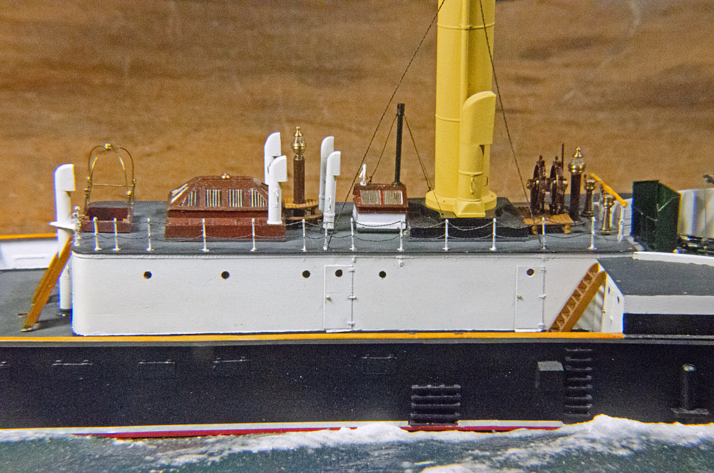
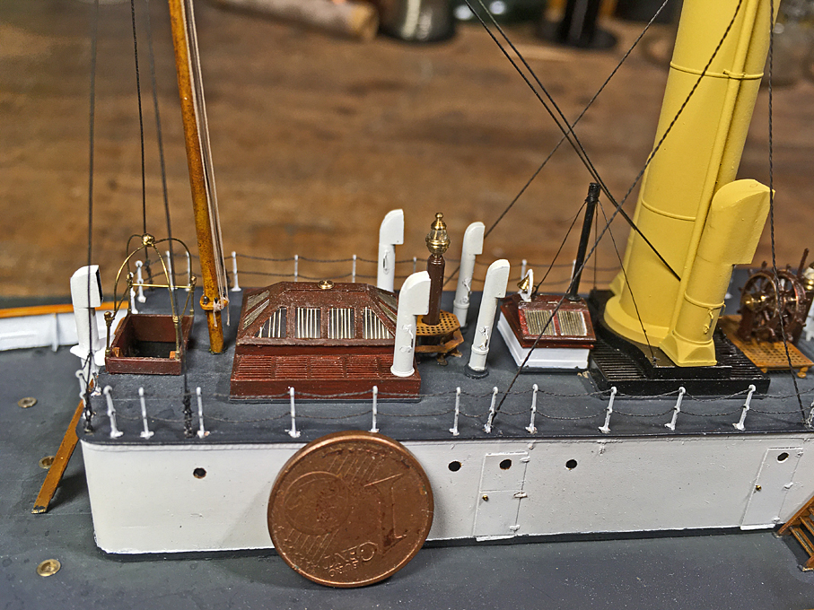
I have installed the rails around the deck-house on the starboard-side too. This time a picture with a coin for size reference.
In the meantime, a forum colleague made the suggestion to braid the wires instead of double-twisting them. I think I had tried this earlier on, but the copper-wires were too soft and broke to easily. I�ll give it a try again with the Konstantan wire and will report. They used chain on this boat for a lot of things, where today one would find wire-rope instead.
Mast and rigging
As noted above, my intention was to work �inside-out� when installing the rails, so as not to damage already installed parts. I now realised that I should have installed also the mast and its stays first, before the deckhouse rails. So, it was high time to do it now, before going on with more rails.
The pictorial evidence is rather scarce for the early form of the mast. In fact, there is only the very first photograph that shows SMS WESPE being fitted out. All other photographs show later forms, when the mast had acquired a top-mast and a fixed signalling yard. When this was installed is not known. Perhaps around the time of the first minor refit, when the boat-racks were installed, or when she got the conning tower with the search-light on top, as shown by the only other photograph with the black/white/yellow livery (as per 1878 regulations).
The mast had been turned a while ago from a steel rod and fitted with belaying pins. Not sure, whether I showed already pictures of this.
It seems that there were double stays leading forward to the front of the boiler-casing, but there are no pictures that show how they were fastened and the drawings are silent on this detail. So, I assumed that there must have been ring-bolts rivetted to the casing. In fact, I should have installed this before painting and installing the casing, but did not have sufficient foresight. Hence, they had to be �retro-fitted� now. Then there is a pair of shrouds on each side � quite a few for a simple pole mast. These shrouds seem to have been made fast on eye-bolts between the rail-stanchions on the deck-house, for which there is a vague indication on the drawings. Again, there is no evidence for how they were set tight. I gather it must have been some hearts with lanyards between them.
I assume that the stays and shrouds were wire-rope. On some later picture it vaguely looks, as if these ropes had been served all over. To imitate such ropes, I have collected over the years electronic copper wires and stranded wires and are spun with silk (as used in high-frequency coils). I choose a 0.15 mm wire for the purpose here. The silk in my case was green, so it had to be given a light coat of black paint first.
Before the shrouds and the stay could go on, the signal halyard blocks had to be installed. I assumed that these were stropped double-blocks, but this is purely conjectural, based on the number of belaying pins. For the signal halyards I used some of my treasured nylon-thread as used in the old days for mending ladies� stockings � a tightly spun two-ply thread that does seem to be out of production now (better than the fly-tying threads). The lay still was not tight enough, so I twisted it a bit more and stabilised the twist with a light touch of varnish.
At that time a steamer should have carried a steamer-light at the mast at night, but the available photographs are not are not clear enough to be sure that it would have been hoisted from a halyard in front of the mast. I just installed the halyard without attempting to model any additional arrangements, such as guiding ropes. The lithograph from the early 1880s also shows a crane for light just in front of the casemate, but it is not visible on the photographs.
Making working hearts for the stays would have been asking a bit too much, so I simplified the arrangements and just provided seized eyes at the end of the standing rigging and roved the lanyards through them and directly through the eyebolts. I gather this is good enough at this small scale. It was difficult enough to install all this without destroying other things already put into place.
To be continued ....
*****************************************
Rails continued �
I have installed the rails around the deck-house on the starboard-side too. This time a picture with a coin for size reference.
In the meantime, a forum colleague made the suggestion to braid the wires instead of double-twisting them. I think I had tried this earlier on, but the copper-wires were too soft and broke to easily. I�ll give it a try again with the Konstantan wire and will report. They used chain on this boat for a lot of things, where today one would find wire-rope instead.
Mast and rigging
As noted above, my intention was to work �inside-out� when installing the rails, so as not to damage already installed parts. I now realised that I should have installed also the mast and its stays first, before the deckhouse rails. So, it was high time to do it now, before going on with more rails.
The pictorial evidence is rather scarce for the early form of the mast. In fact, there is only the very first photograph that shows SMS WESPE being fitted out. All other photographs show later forms, when the mast had acquired a top-mast and a fixed signalling yard. When this was installed is not known. Perhaps around the time of the first minor refit, when the boat-racks were installed, or when she got the conning tower with the search-light on top, as shown by the only other photograph with the black/white/yellow livery (as per 1878 regulations).
The mast had been turned a while ago from a steel rod and fitted with belaying pins. Not sure, whether I showed already pictures of this.
It seems that there were double stays leading forward to the front of the boiler-casing, but there are no pictures that show how they were fastened and the drawings are silent on this detail. So, I assumed that there must have been ring-bolts rivetted to the casing. In fact, I should have installed this before painting and installing the casing, but did not have sufficient foresight. Hence, they had to be �retro-fitted� now. Then there is a pair of shrouds on each side � quite a few for a simple pole mast. These shrouds seem to have been made fast on eye-bolts between the rail-stanchions on the deck-house, for which there is a vague indication on the drawings. Again, there is no evidence for how they were set tight. I gather it must have been some hearts with lanyards between them.
I assume that the stays and shrouds were wire-rope. On some later picture it vaguely looks, as if these ropes had been served all over. To imitate such ropes, I have collected over the years electronic copper wires and stranded wires and are spun with silk (as used in high-frequency coils). I choose a 0.15 mm wire for the purpose here. The silk in my case was green, so it had to be given a light coat of black paint first.
Before the shrouds and the stay could go on, the signal halyard blocks had to be installed. I assumed that these were stropped double-blocks, but this is purely conjectural, based on the number of belaying pins. For the signal halyards I used some of my treasured nylon-thread as used in the old days for mending ladies� stockings � a tightly spun two-ply thread that does seem to be out of production now (better than the fly-tying threads). The lay still was not tight enough, so I twisted it a bit more and stabilised the twist with a light touch of varnish.
At that time a steamer should have carried a steamer-light at the mast at night, but the available photographs are not are not clear enough to be sure that it would have been hoisted from a halyard in front of the mast. I just installed the halyard without attempting to model any additional arrangements, such as guiding ropes. The lithograph from the early 1880s also shows a crane for light just in front of the casemate, but it is not visible on the photographs.
Making working hearts for the stays would have been asking a bit too much, so I simplified the arrangements and just provided seized eyes at the end of the standing rigging and roved the lanyards through them and directly through the eyebolts. I gather this is good enough at this small scale. It was difficult enough to install all this without destroying other things already put into place.
To be continued ....
Eberhard
Former chairman Arbeitskreis historischer Schiffbau e.V. (German Association for Shipbuilding History)
--------------------------------------------------------------------------------------------------------------------------------------------------------------------------------------------
Former chairman Arbeitskreis historischer Schiffbau e.V. (German Association for Shipbuilding History)
--------------------------------------------------------------------------------------------------------------------------------------------------------------------------------------------
-
Maarten Sch�nfeld
- Posts: 1835
- Joined: Fri Dec 12, 2008 12:44 pm
- Location: Herk-de-Stad, Belgium
Re: 1:160 S.M.S. WESPE Armoured Gunboat (1876)
Looking awesome, Wefalck! Step by step to the finish...
Constantan wire... I woud expect it to be more brittle and springy than copper wire. But maybe I'm mistaken?
Constantan wire... I woud expect it to be more brittle and springy than copper wire. But maybe I'm mistaken?
"I've heard there's a wicked war a-blazing, and the taste of war I know so very well
Even now I see the foreign flag a-raising, their guns on fire as we sail into hell"
Roger Whittaker +9/13/2023
Even now I see the foreign flag a-raising, their guns on fire as we sail into hell"
Roger Whittaker +9/13/2023
-
wefalck
- Posts: 2079
- Joined: Wed Sep 28, 2011 12:04 pm
- Location: Paris
- Contact:
Re: 1:160 S.M.S. WESPE Armoured Gunboat (1876)
Thanks Maarten.
Kontantan is more springy, which is the good point, but the breaking strength is greater than that of pure copper.
Kontantan is more springy, which is the good point, but the breaking strength is greater than that of pure copper.
Eberhard
Former chairman Arbeitskreis historischer Schiffbau e.V. (German Association for Shipbuilding History)
--------------------------------------------------------------------------------------------------------------------------------------------------------------------------------------------
Former chairman Arbeitskreis historischer Schiffbau e.V. (German Association for Shipbuilding History)
--------------------------------------------------------------------------------------------------------------------------------------------------------------------------------------------