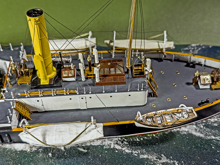
The Ship Model Forum

The Ship Modelers Source
It is currently Sun Jun 29, 2025 12:03 pm

All times are UTC - 6 hours [ DST ]


Post new topic Reply to topic  [ 405 posts ]  Go to page Previous  1 ... 16, 17, 18, 19, 20, 21  Next
Author Message
PostPosted: Mon Feb 05, 2024 3:49 pm 
Offline
User avatar

Joined: Wed Sep 28, 2011 12:04 pm
Posts: 1965
Location: Paris
Well, some traveling and struggles with tiny and flimsy parts caused again a long delay until this update …

Installing the ship’s boats

This detail was the most dreaded of all, due to the flimsy character of the parts. The davits had been produced a long time ago, as were the blocks for the hoisting tackle, and, of course the four boats.

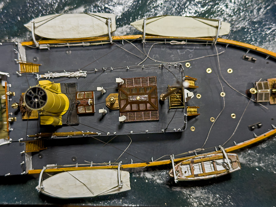
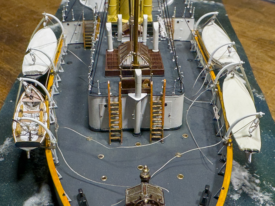
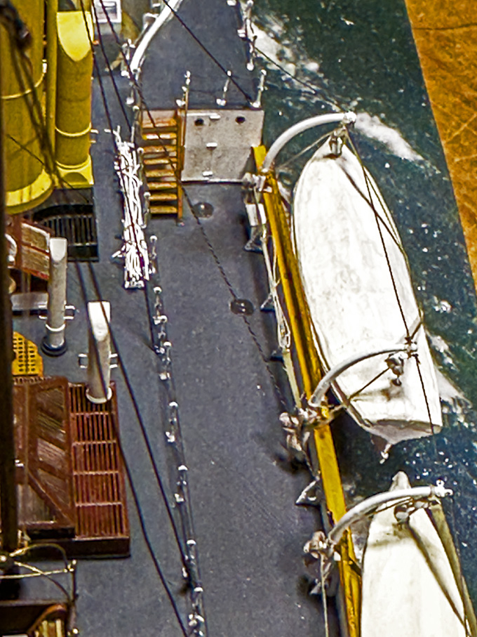
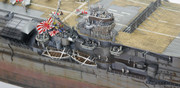
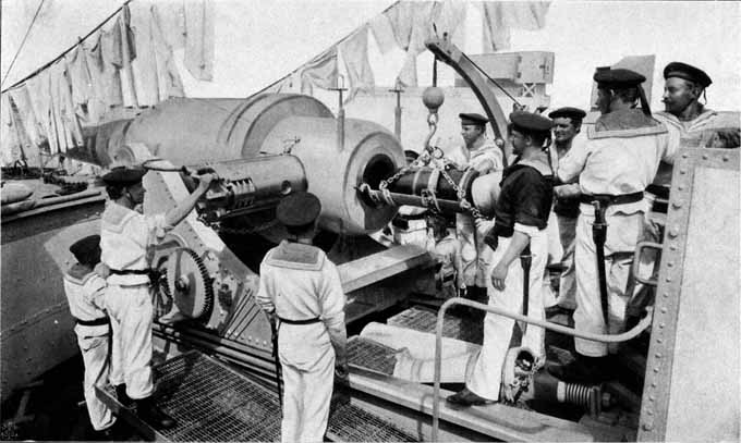
There are no pictures, except the very first photograph of SMS WESPE that indicate the arrangements for the boats hanging outboard on the davits. While it seems to have been a quite common arrangement on smaller warships of the time, it was already noted in reports by captains of Prussian gunboats ten years earlier, boats in such a position are prone to be carried away by seas of even moderate height. So, quite early on barrings and boat skids had been installed on the WESPE-class boat and the davits lengthened to lift up the boats. For this final arrangement, various images are available.

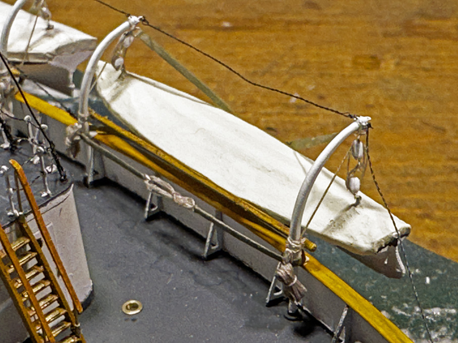
Somehow, the boats must have been prevented from swinging in their hoisting gear. A typical arrangement would have been a spar lashed across the davits and the boats pulled against them with cross-wise boat ties. In the absence of other pictorial evidence, this is what I opted for. There were, however, still some detail questions open: were those ties strips of heavy canvas or braided rope-work and did the spars have bolsters around them to prevent damage to the boats? For the latter questions there are examples of both option on photographs and (contemporary) models.

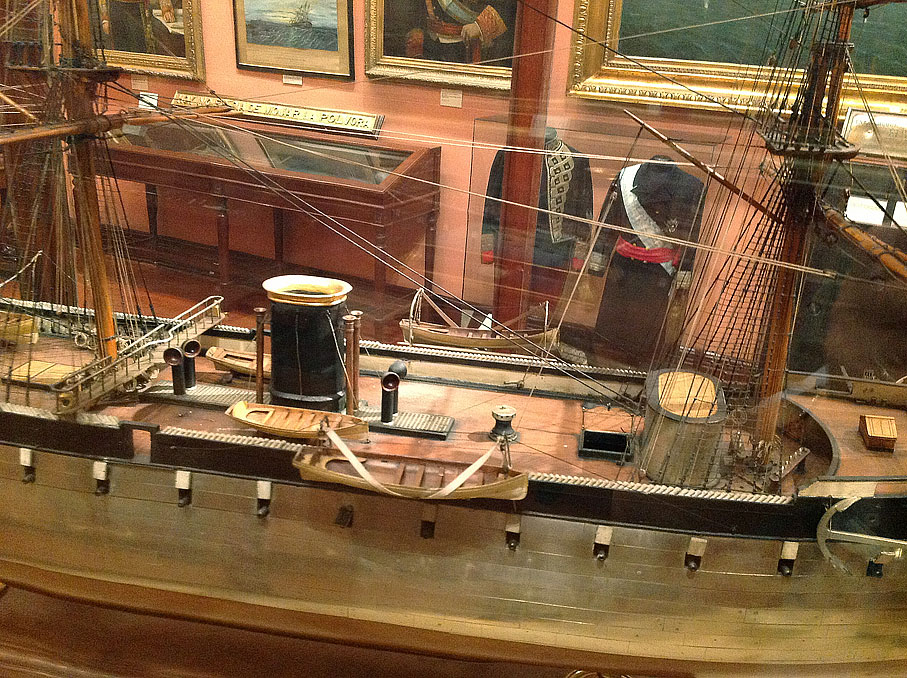
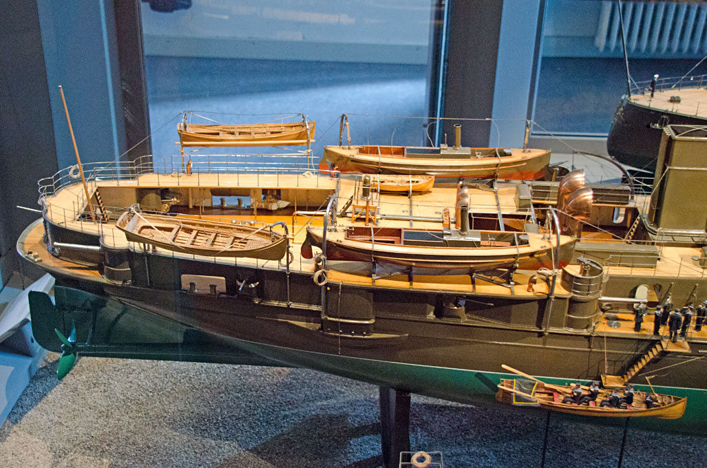
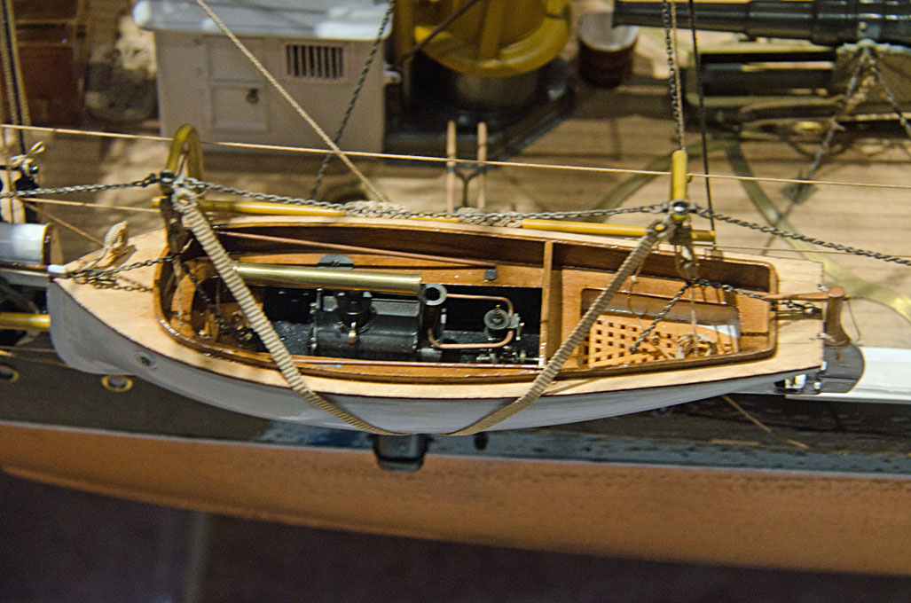
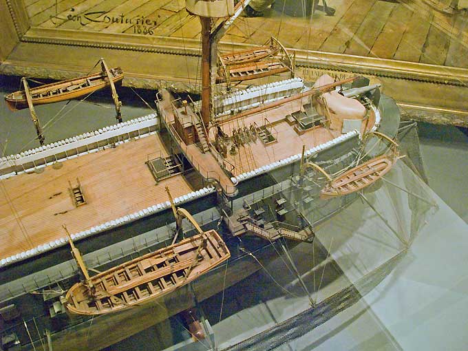
I recently visited again the Maritime Museum in Stockholm, which reminded me of a possible solution on a model of the same period. The boat-ties seem to have been heavy canvas and had triangular rings at their ends. They are attached to an eye at the top of the davit, run around the boat, then around the opposite davit, and are hauled taught with a tackle of blocks hooked in between them. No bolsters on the spars.

I decided to leave out the tackle and just use a lashing between the rings to tighten the ties. The lashing will be difficult enough to access behind the boats.

Image
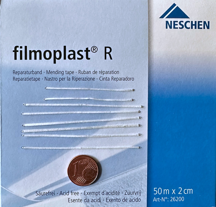
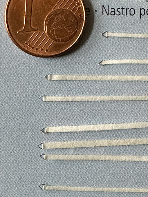
Boat ties arrange on a package of book-repair tape

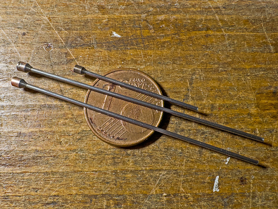
The triangular rings were fashioned from 0.15 mm tinned copper-wire wound around the tang of a triangular file with 1 mm sides. The windings were cut open with a scalpel. The ties themselves are narrow strips of a special kind of material: a kind of very fine silk-paper tape with a backing of a thermos-setting acrylic glue. This material is used in book repair for instance. Brand and other details can be seen on the photograph. The 1 mm strips were cut with a new no. 11 scalpel blade and folded in two. The material is slightly tacky which is helpful when aligning the halves and inserting the rings. The glue was set with the help of my hot-air soldering gun set to 110°C as per instructions. The halves were pushed together using a tool as used in the old days to rub down transfer lettering. The ties were painted in Vallejo ‘hemp’.

Image
Boat ties in detail.

It took some tries to work out a workable sequence for installing the davits, spar, boat-ties and boat-tackles, considering also the difficulty of access. Eventually the ties were fastened to the davits and the tackles hooked into the latter with the loose end already belayed to the clamp on the back of the davits.

Image
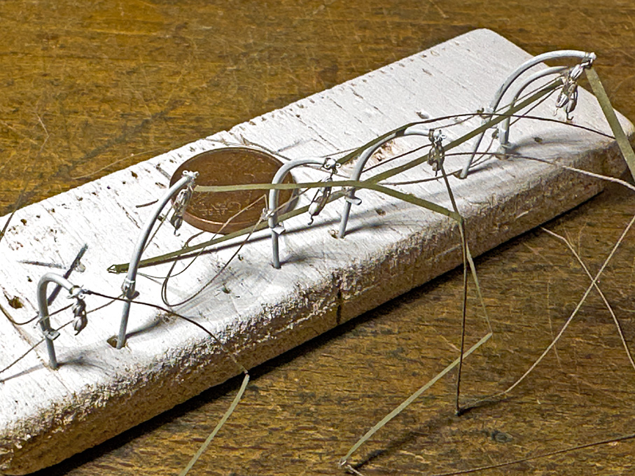
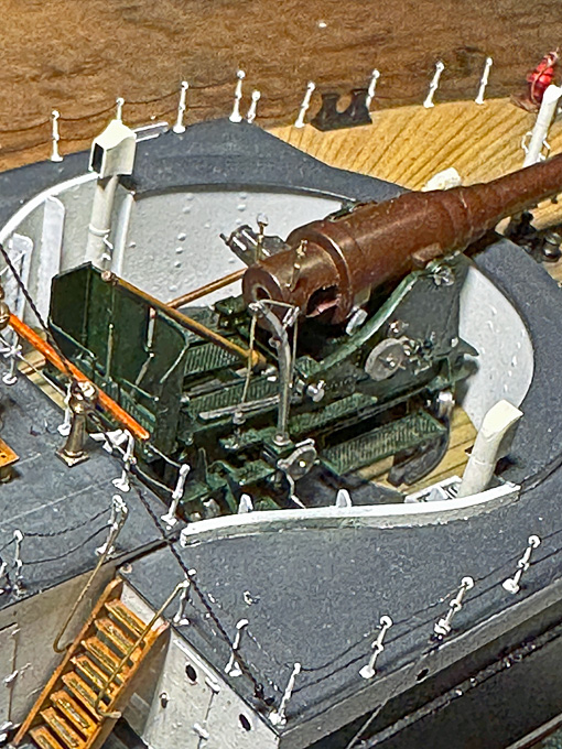
Davits fitted out and ready for installation on board.

The davits then were inserted into their sockets and fixed with a drop of white glue. Next the spar is lashed to the davits. Then the ties were arranged in preparation of the boats and the lashing is reeved.

Image
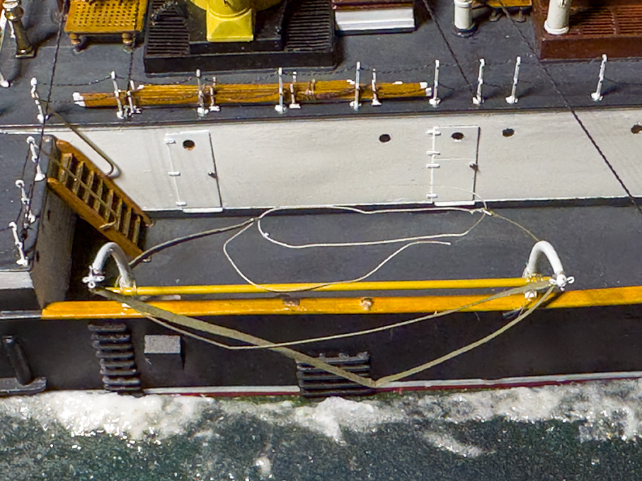
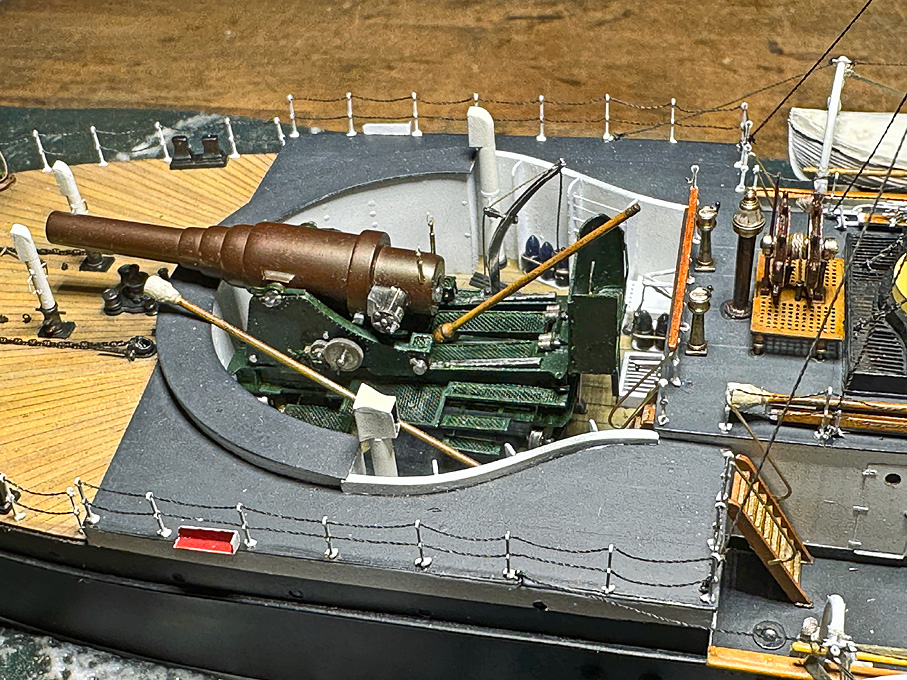
Davits ready to receive the boat.

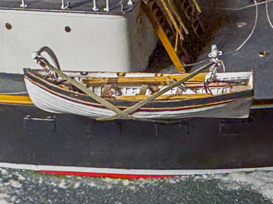
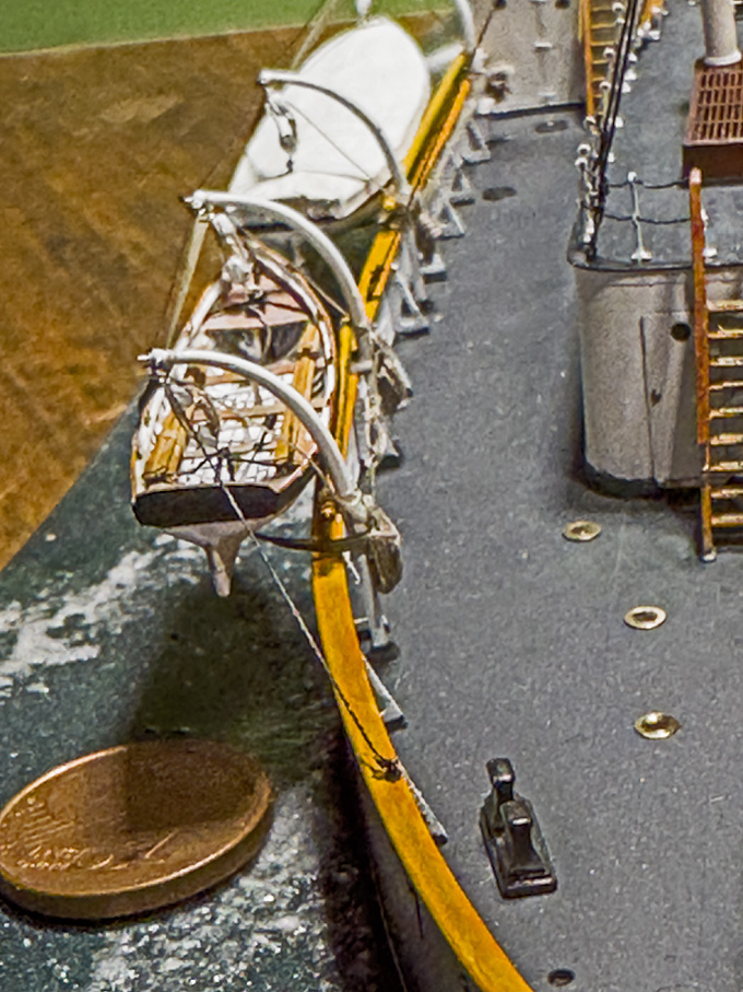
The davits are now ready to receive the boat, which is slipped in and the tackles hooked into the respective rings on the boat. The ties are now pulled tight, so that boat rests against the spar.

Image
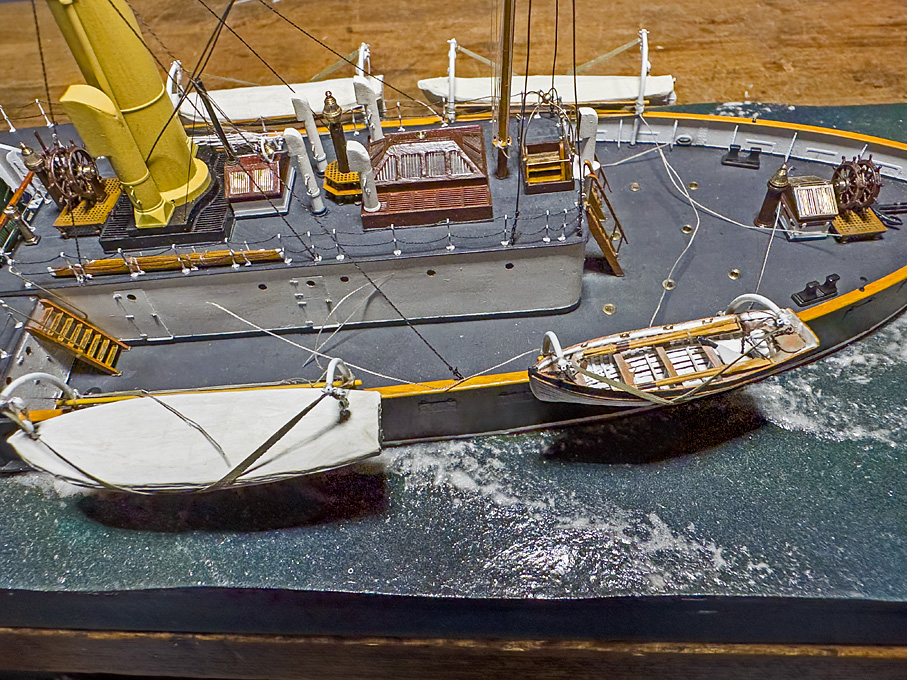
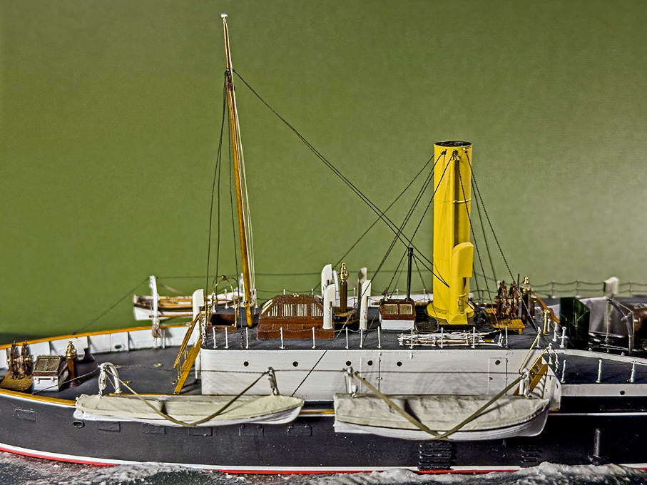
Boat stowed in the davits.

Overall, the installation of the first boat went reasonably well. However, it is hanging a few millimetres too low. The boat’s keel should have been level with the bulwark handrail. Somehow, I didn’t manage to make the close-hauled tackled as short as it should have been. Also, the hooks on the blocks are a tad too long. Not 100% satisfactory, but I am not going back two steps to remake the blocks and tackles and all. Let’s assume the crew hasn’t done such a good job in stowing the boats and the officers haven’t noticed it yet …

To be continued ....

_________________
Eberhard

Former chairman Arbeitskreis historischer Schiffbau e.V. (German Association for Shipbuilding History)

--------------------------------------------------------------------------------------------------------------------------------------------------------------------------------------------

Image Image Image Image


Report this post
Top
 Profile  
Reply with quote  
PostPosted: Tue Feb 06, 2024 4:40 pm 
Offline
User avatar

Joined: Tue Sep 29, 2020 4:35 pm
Posts: 1881
Location: Bretagne, France
It's always tricky to change things after they've been done!

But you come out of it well, this detail is worth it. :thumbs_up_1: I seem to have seen this strap system elsewhere, perhaps in the US Navy.

Davits are still a problem even today on ships. They're dangerous, both for the lifeboat and for the sailors. I've used and maintained a lot of them in my career, and they require a lot of maintenance, not to mention design faults...

It's been reported that davits have killed more sailors than they've saved. We had one fatality in my company, a young man, a ball bearing broke during a test. Since then, boats are only lowered and raised with the davit without a sailor on board.

The free-fall system is much safer.. and efficient, from experience.

https://www.nautinst.org/uploads/assets ... 57fe49.pdf

_________________
Pascal

•Battleship Bretagne 3D: https://vu.fr/FvCY
•SS Delphine 3D: https://vu.fr/NeuO
•SS Nomadic 3D: https://vu.fr/tAyL
•USS Nokomis 3D: https://vu.fr/kntC
•USS Pamanset 3D: https://vu.fr/jXGQ


Report this post
Top
 Profile  
Reply with quote  
PostPosted: Wed Feb 07, 2024 2:46 am 
Offline

Joined: Tue Feb 06, 2007 10:24 am
Posts: 2584
Location: Belgium
Wonderful! Fantastic details! :thumbs_up_1: :thumbs_up_1: :thumbs_up_1:


To get the height exactly to your liking on the next one, it may help not to attach it like the real thing, but in (more or less) reverse order:
- glue the boat to the spar, at exactly the height/position you want it to be;
- attach the tackles in between boat and davits;
- attach the straps.


Report this post
Top
 Profile  
Reply with quote  
PostPosted: Wed Feb 07, 2024 3:50 am 
Offline
User avatar

Joined: Wed Sep 28, 2011 12:04 pm
Posts: 1965
Location: Paris
Ship's boats on warship were not exactly life-boats, but rather work-boats. For security reasons (preventing illicit traffic from and to the ship) warships typically were moored to buoys or anchored in harbours and roadsteads. The boat ensured the transport of personnell and supplies, but also were used for landing and reconnaisance operations and such. Usually only one boat was kept ready for emergencies, which is why I built the smallest boat uncovered.

Lowering boats from davits in anything but calm weather and a stationary ship was a dangerous operation. The hooks from the boat-tackles had to be released simultaneously. Imagine what will happend if the hook in the stern is released a second too late, when there is a sea passing under the ship. The boat's bow will undercut the wave and overturn the boat, while the stern is still suspended from the davit ... This is why slip-hooks were invented and patent-applications and publications abound with suggestions for quick-release gears that allow to release both hooks simultaneously. While slip-hooks were used in the Imperial German Navy, the quick-release gear never seems to have caught on (pun intended ...).

I know of numerous photographs and contemporary models from all over the world, where these boat-ties are shown, when boats are kept suspended from davits. This applies to both, naval and merchant navy ships. The ties could be strips of canvas, plaits, or simple ropes. When boats rested in chocks under the davits, so-called gripes were used to tie them down.

The problem I had, was that the tackles turned out too long. The reason was partly that the fake splices for the runners became a bit too long and would not run over the 'sheave' in the block, and partly that the took turned out too long as well. Maybe also the ring in the boats should have been lower. Just a fraction of millimetre error in each element adds up. There are so many degrees of freedom or variables in the system that are difficult to determine a priori. It's not like machining a piece to dimensions ...

_________________
Eberhard

Former chairman Arbeitskreis historischer Schiffbau e.V. (German Association for Shipbuilding History)

--------------------------------------------------------------------------------------------------------------------------------------------------------------------------------------------

Image Image Image Image


Report this post
Top
 Profile  
Reply with quote  
PostPosted: Sun Feb 11, 2024 2:14 pm 
Offline
User avatar

Joined: Wed Sep 28, 2011 12:04 pm
Posts: 1965
Location: Paris
Installing the ship’s boats 2

It is done! All four boats are suspended from their davits and the work was achieved without major damage to other parts.

Good thing that there is not (yet) any brain recorder … because of the mental language that accompanied the process at certain stages.

Still there is a lot to be done, such as tidying up the loose ends, making and installing the coils of rope from the runners of the boat-tackles and the longitudinal chain-stays for the davits.

Image

Image

Image

Image


To be continued ....

_________________
Eberhard

Former chairman Arbeitskreis historischer Schiffbau e.V. (German Association for Shipbuilding History)

--------------------------------------------------------------------------------------------------------------------------------------------------------------------------------------------

Image Image Image Image


Report this post
Top
 Profile  
Reply with quote  
PostPosted: Sun Feb 11, 2024 2:43 pm 
Offline
User avatar

Joined: Fri Dec 12, 2008 12:44 pm
Posts: 1813
Location: Herk-de-Stad, Belgium
My congratulations, Eberhard! Finish in sight, as you described.

A very interesting ship, and a more than interesting build: research, plan and execution. I learned a lot from you in the meantime. Thanks!

_________________
"I've heard there's a wicked war a-blazing, and the taste of war I know so very well
Even now I see the foreign flag a-raising, their guns on fire as we sail into hell"
Roger Whittaker +9/13/2023


Report this post
Top
 Profile  
Reply with quote  
PostPosted: Wed Feb 14, 2024 5:04 am 
Offline

Joined: Tue Feb 06, 2007 10:24 am
Posts: 2584
Location: Belgium
Wonderful! Those boats add so much to the overall feel of the model. :thumbs_up_1: :thumbs_up_1: :thumbs_up_1:


Report this post
Top
 Profile  
Reply with quote  
PostPosted: Thu Feb 15, 2024 6:12 am 
Offline

Joined: Sat Sep 17, 2005 9:19 am
Posts: 1552
Very nice Wasp. What's next?


Report this post
Top
 Profile  
Reply with quote  
PostPosted: Thu Feb 15, 2024 11:18 am 
Offline

Joined: Wed Jan 21, 2009 1:51 pm
Posts: 2874
Wonderful work on those boats and davits... :thumbs_up_1:


Report this post
Top
 Profile  
Reply with quote  
PostPosted: Sat Mar 09, 2024 7:44 am 
Offline
User avatar

Joined: Wed Sep 28, 2011 12:04 pm
Posts: 1965
Location: Paris
Thank you very much for your kind comments, much appreciated !

********************************************************************

Installing the ship’s boats 3

The installation was movd further to completion by tidying up the loose ends and producing the bunts for runners of the boat tackles. The runners are about five times the distance between the head of the davits and the waterline long, plus some extra for handling. However, as the rope is slightly overscale the runners were cut a bit on the short side in order to make the bunts not too bulky. The actual runners were cut above the cleats and the bunts were formed over two clothes pins driven into a piece of wood and have a loop pulled out with which they can be hung over their respective cleat.

Image

Note that the runners for the ‘ready’ boat are not arranged in bunts but in coils, ready to be thrown loose so as to allow the boat being lowered quickly e.g. in a case of man-over-board.

Image

Again, working from the inside out, the next items to go on were the stays for the davits. Luckily, the stays are drawn in the lithographs so that their points of fixation are known. I had to deviate a bit from those drawings, as they pertain to the longer, turning davits for the boats stored on rack, which belong to a slightly later period. The stays are supposed to keep the davits aligned, rather than helping to swing them around.

Image

It was a bit of a trial-and-error procedure, before I came up with a protocol for making miniature fake chains of exactly the right length and with loops at both ends. The chains would have been shackled into ring-bolts at the head of the davit. No way of making shackles in this scale, so I just tied the fake chains to ring-bolts with fly-tying thread.

Image

Some people may think now that’s it, but in fact there still is quite a long to-do list for little details:

- davit for the stern-anchor
- flag-poles and flags
- for the gun: tampon, wiper, rammer, and two gun-sights
- and the … crew!

Image


To be continued ....

_________________
Eberhard

Former chairman Arbeitskreis historischer Schiffbau e.V. (German Association for Shipbuilding History)

--------------------------------------------------------------------------------------------------------------------------------------------------------------------------------------------

Image Image Image Image


Report this post
Top
 Profile  
Reply with quote  
PostPosted: Sat Mar 09, 2024 9:31 am 
Offline
User avatar

Joined: Tue Sep 29, 2020 4:35 pm
Posts: 1881
Location: Bretagne, France
Beautiful model! :cool_1:

Iceman 29 wrote:
..... I seem to have seen this strap system elsewhere, perhaps in the US Navy.


IJN also use this method:

https://www.britmodeller.com/forums/ind ... of-midway/

Image

_________________
Pascal

•Battleship Bretagne 3D: https://vu.fr/FvCY
•SS Delphine 3D: https://vu.fr/NeuO
•SS Nomadic 3D: https://vu.fr/tAyL
•USS Nokomis 3D: https://vu.fr/kntC
•USS Pamanset 3D: https://vu.fr/jXGQ


Report this post
Top
 Profile  
Reply with quote  
PostPosted: Sat Mar 09, 2024 6:00 pm 
Offline
User avatar

Joined: Wed Sep 28, 2011 12:04 pm
Posts: 1965
Location: Paris
Actually, many navies (incl. merchant) used it:

Image
The Spanish NUMANTIA

Image
The Swedish GÖTA

Image
The Portuguese BENGO

Image
The French TRIDENT

These are all examples of the time between 1867 and 1879. Sometimes simple ropes were used, as per photographic evidence. I gather these boat-ties were used as long as boats were hung outboard on davits. When boats were put on skids, gripes are used, as in the old days.

_________________
Eberhard

Former chairman Arbeitskreis historischer Schiffbau e.V. (German Association for Shipbuilding History)

--------------------------------------------------------------------------------------------------------------------------------------------------------------------------------------------

Image Image Image Image


Report this post
Top
 Profile  
Reply with quote  
PostPosted: Sun Mar 10, 2024 5:30 am 
Offline
User avatar

Joined: Tue Sep 29, 2020 4:35 pm
Posts: 1881
Location: Bretagne, France
Nice doc pictures! :thumbs_up_1:

_________________
Pascal

•Battleship Bretagne 3D: https://vu.fr/FvCY
•SS Delphine 3D: https://vu.fr/NeuO
•SS Nomadic 3D: https://vu.fr/tAyL
•USS Nokomis 3D: https://vu.fr/kntC
•USS Pamanset 3D: https://vu.fr/jXGQ


Report this post
Top
 Profile  
Reply with quote  
PostPosted: Sun Mar 10, 2024 6:01 am 
Offline
User avatar

Joined: Wed Sep 28, 2011 12:04 pm
Posts: 1965
Location: Paris
In case you weren't aware, here are more: https://www.maritima-et-mechanika.org

_________________
Eberhard

Former chairman Arbeitskreis historischer Schiffbau e.V. (German Association for Shipbuilding History)

--------------------------------------------------------------------------------------------------------------------------------------------------------------------------------------------

Image Image Image Image


Report this post
Top
 Profile  
Reply with quote  
PostPosted: Sun Mar 17, 2024 3:32 pm 
Offline
User avatar

Joined: Wed Sep 28, 2011 12:04 pm
Posts: 1965
Location: Paris
Toolkit for the gun

The operation of the gun required quite a few different tools for handling the projectiles and the powder-bags, as well as for cleaning and maintenance.

There were two different wipers, one for cleaning with soap-water and the other one for greasing the bore after use. This still was the era of black powder, which means that the bore had to be cleaned frequently.

Loading required a rammer to push the projectile and the powder-bags into the chamber of the gun. The rammer also served to unload the gun by pushing it through the muzzle. It had a depression in the front so that one would not push onto the fuse.
The large-scale instruction model in the (former) Orlogmuseet in Copenhagen came with many of the necessary tools. Their look tallies with the description of a textbook on the Imperial German naval artillery (Galster, 1885). The length of the shaft was given as the length of the barrel plus some extra for one or two men to be able to hold onto it, while it was fully inserted. If there were not enough space for such long implements, there were also versions in two parts with a brass connecting sleeve.

Image
Wiper (top) and rammer (bottom)

The body of the implements was turned from some 2 mm steel rod, as I had this to hand. The shaft is a 0.8 mm piano wire. The latter appears to be quite hefty, but seems to tally with the photographs.

Image
Wipers and rammer before painting

As the gun will be shown undergoing a drill, the wipers are not needed and will be shown in their protective canvas covers, stored in the racks on deckhouse as per photograph below.

Image
Wipers in their protective canvas covers

The canvas covers were simulated with some Vallejo liquid putty. According to Galster (1885) the covers were supposed to be painted black, but the above photograph indicates that they were white, which is what I opted for.
The rammer body has two copper-bands to protect it, which were simulated with paint. The limited space in barbette seems to prevent the use of a full-length rammer, so I gave the end of the shaft a connecting sleeve simulated with paint.

Tampion
The photograph of the instruction model in Copenhagen also shows the expanding tampion that was constructed from two brass discs with some fibre material in between that was contained by a leather sleeve. An internal screw operated by a T-shaped handle squeezed the fibres between the disc and made them expand to lock into the muzzle.

Image
Expanding tampion for the 30,5 cm gun

The tampion is probably going to be the very last machined part on this model. It was turned from a length of brass rod. The handle was first turned as a thin disk and then the excess material was milled away to leave the T-shaped handle standing. The greased leather sleeve has been simulated by some brown paint.

Image
Turning the tampion

Image
Milling the tampion T-handle

Image
The finished wipers, rammer and tampion

Next on the list are the anchor-crane, the flagpole and flag and finally the gun-sights

To be continued ....

_________________
Eberhard

Former chairman Arbeitskreis historischer Schiffbau e.V. (German Association for Shipbuilding History)

--------------------------------------------------------------------------------------------------------------------------------------------------------------------------------------------

Image Image Image Image


Report this post
Top
 Profile  
Reply with quote  
PostPosted: Sun Mar 17, 2024 3:56 pm 
Offline
User avatar

Joined: Tue Sep 29, 2020 4:35 pm
Posts: 1881
Location: Bretagne, France
wefalck wrote:
In case you weren't aware, here are more: https://www.maritima-et-mechanika.org


I visited it a few monts ago, and I haven't finished yet.

There's a lot of information to read and some beautiful photos. The amount of work that went into putting it all together is impressive.

Your wipers are very realistic.
On merchant ships, the man in charge of cleaning the engine room is still known as the "Wiper" or "Nettoyeur" in French.
The appropriate term ashore is "surface technician". :big_grin:

_________________
Pascal

•Battleship Bretagne 3D: https://vu.fr/FvCY
•SS Delphine 3D: https://vu.fr/NeuO
•SS Nomadic 3D: https://vu.fr/tAyL
•USS Nokomis 3D: https://vu.fr/kntC
•USS Pamanset 3D: https://vu.fr/jXGQ


Report this post
Top
 Profile  
Reply with quote  
PostPosted: Sun Mar 17, 2024 4:33 pm 
Offline
User avatar

Joined: Wed Sep 28, 2011 12:04 pm
Posts: 1965
Location: Paris
Ahh, the male equivalent to a 'masseuse de parquet' :big_grin:

_________________
Eberhard

Former chairman Arbeitskreis historischer Schiffbau e.V. (German Association for Shipbuilding History)

--------------------------------------------------------------------------------------------------------------------------------------------------------------------------------------------

Image Image Image Image


Report this post
Top
 Profile  
Reply with quote  
PostPosted: Sun Mar 17, 2024 5:56 pm 
Offline
User avatar

Joined: Tue Sep 29, 2020 4:35 pm
Posts: 1881
Location: Bretagne, France
:big_grin:

_________________
Pascal

•Battleship Bretagne 3D: https://vu.fr/FvCY
•SS Delphine 3D: https://vu.fr/NeuO
•SS Nomadic 3D: https://vu.fr/tAyL
•USS Nokomis 3D: https://vu.fr/kntC
•USS Pamanset 3D: https://vu.fr/jXGQ


Report this post
Top
 Profile  
Reply with quote  
PostPosted: Mon Mar 25, 2024 12:22 pm 
Offline
User avatar

Joined: Wed Sep 28, 2011 12:04 pm
Posts: 1965
Location: Paris
WOW, in the meantime this building log has received 100,000 clicks. 25,000 alone the last three weeks. I am impressed and pleased ... I wonder what it made suddently so popular and hope it is not just a robot ...

A big thank you for your interest :thumbs_up_1:

_________________
Eberhard

Former chairman Arbeitskreis historischer Schiffbau e.V. (German Association for Shipbuilding History)

--------------------------------------------------------------------------------------------------------------------------------------------------------------------------------------------

Image Image Image Image


Report this post
Top
 Profile  
Reply with quote  
PostPosted: Fri Mar 29, 2024 10:52 am 
Offline
User avatar

Joined: Wed Sep 28, 2011 12:04 pm
Posts: 1965
Location: Paris
I am really puzzled by those many 'clicks' on this thread - 1800 in just four days ...

*************************************************************************************
Anyway, just a little bit of further progress before the Easter-weekend …

Stern anchor-crane

There are drawings as well as the photograph below that show the anchor-crane in some detail.

Image

Basically, the dimensions are the same as that of the boat-davits, so that I was able to use a spare one that was left over. The ball at the end was drilled for the ring into which during service the anchor-tackle would be hooked. When not in service, the davit was steadied with two chain-stays.

Image

Image


The set-up is very similar to that of the boat davits and the same processes were used.

Gun-sights

Gun-aiming technology didn’t significantly progress until towards the end of the 19th century. Just very basic front sights were used that sat on the trunnions, while the rear sights were adjustable in height for different distances and laterally for lead-angles. The rear sights used on the 30,5 cm gun a clearly visible on photograph below. Galster (1885) gives a detailed description. Basically, it is brass-tube of about 4 cm diameter that is set into a whole drilled vertically through the rear of the gun. In this tube runs a graduated brass-rod for setting the elevation as a function of the type of projectile used and the size of the powder charge. Firing tables were provided with the gun. On top of the rod is a cross-piece that runs in a dovetail-slot and allows to pre-set the lead-angle. The lead-angle was calculated inter alia on the basis of the estimated relative speed of the target and its distance. There was the usual V-notch on the top of cross-piece.

Image

It took several tries to produce these tiny pieces. In the end their dimensions are slightly over-scale due to the limitations of machining brass. Starting from 0.8 mm brass-nails, which are slightly harder than the usual brass wire due to the forging process, a 1.5 mm length of 0.2 mm diameter was step-turned over short lengths successively. Then a 0.2 mm long length was turned down to 0.7 mm diameter and this ‘rod’ with a disc at the end parted off. Luckily, I have a 0.2 mm collet for the lathe, so that the part could be inverted and the parted-off end cleaned up. With a pair of cutting-tweezers the disc was clipped down to the size of the cross-piece. Burrs were removed with a fine file.
This part fits into a 2 mm long section of 0.3 mm OD brass-tube (from Albion metals).

Image

When I made the gun-barrel in about 2008, I did not have really the technology to safely drill to any depths the 0.3 mm holes for the sights, I was glad to be able to mill the flats with a broken drill that I had ground flat at the end. With my micro-milling machine and the dividing head this would not be a real issue anymore. Unfortunately, I forgot to do that before painting the barrel. Therefore, the sights had to be simply cemented onto the flats with a tiny drop of shellac.
Before doing that I also added the protective frames over the sights using some 0.007 mm diameter silver-wire.

Image

Also installed were the last two of the ventilators for the officers’ mess.

What remains now is the flagstaff and the ensign. I have already found a suitable technique for the complex ensign of the Imperial German Navy, but have to still get the right red for it.

And then on to the crew …


To be continued ....

_________________
Eberhard

Former chairman Arbeitskreis historischer Schiffbau e.V. (German Association for Shipbuilding History)

--------------------------------------------------------------------------------------------------------------------------------------------------------------------------------------------

Image Image Image Image


Report this post
Top
 Profile  
Reply with quote  
Display posts from previous:  Sort by  
Post new topic Reply to topic  [ 405 posts ]  Go to page Previous  1 ... 16, 17, 18, 19, 20, 21  Next

All times are UTC - 6 hours [ DST ]


Who is online

Users browsing this forum: FFG-7 and 6 guests


You can post new topics in this forum
You can reply to topics in this forum
You cannot edit your posts in this forum
You cannot delete your posts in this forum
You cannot post attachments in this forum

Jump to:  
Powered by phpBB® Forum Software © phpBB Group