I had the same issue looking for detailed pics for my 1/800 TR. The black netting follows the framing of the escape trunk. I just used a flat piece of brass from an etched parts set, cut it and bent it to shape. Then I put the square pieces for the blast shield area.
Found these- they might help get a more correct look for -65:
EJM wrote:I'm trying to create a better LSO platform area on my TAMIYA Enterprise carrier. The below pics are of the LSO area on the Gerald Ford class carriers. But the black colored "basket" for lack of a better word is fairly common on the LSO area on US Navy carriers. How can I create this for my Enterprise carrier? Is there an aftermarket set available or not? If not, then any tips and techniques for scratch building this?
Timmy C wrote:How would you model the fo'c'sle? I didn't even think a postwar carrier would have a fo'c'sle, but I guess it makes sense to still call the anchor chain handling deck that. Here's a pic of Kitty Hawk's: https://www.alamy.com/stock-photo-03102 ... 17542.html
I�ve got a pretty unique opportunity with my latest build. I�m lifting the flight deck 4� off the hull with a set of linear motors. As a result the bow area will be visible. Since the anchor hause holes are just above the deck on the Trumpeter 1/350 KittyHawk i thought i�d add some interest to this area and model the focsle.
I found a few pics on that same sight. Hoping someone has some cleaner shots that really show the layout.
Here�s what i have to start with
If you wish to develop your upper body musculature, you might take on Dave McKay's USS Enterprise, CVA(N)/CVA-65: The World's First Nuclear-Powered Aircraft Carrier. It runs to almost 700 pages, is lavishly illustrated, and weighs in at a little under six pounds (2.75 kilos).
Has anybody used the Starfighter Decals 1/350 scale USS Enterprise CVN-65 set for their TAMIYA Enterprise carrier model?
When I looked at the #4 decals for around the jet blast deflectors, I noticed they were all too large and don't fit properly around the JBD's on the model.
The same is also for the #'s 7 and 8 decals for the crash barricade supports.
Anyway, I'm not putting any of those numbered decals on my carrier.
Is there some other aftermarket Enterprise decals I can get that have better sized/fitting decals for the JBD's and the crash barricade supports?
When we say the Enterprise length is 342 m after refit does this means from end of the back were the last sponsos or safety net are (whichever extrudes furthest i guess) to the very front end of the Bow Prongs and their safety nets or this just includes the flight deck without any extrusions aft and fore of the bow?
Did the Enterprise got lengthened with extra section added at the hull after its major refit because the length before and after the refit is considerably different from the online sources at least (332m vs 342m ) or is it just extra platforms at the back /safety nets etc?
angeleyes wrote:Got a question a bit silly.
When we say the Enterprise length is 342 m after refit does this means from end of the back were the last sponsos or safety net are (whichever extrudes furthest i guess) to the very front end of the Bow Prongs and their safety nets or this just includes the flight deck without any extrusions aft and fore of the bow?
Did the Enterprise got lengthened with extra section added at the hull after its major refit because the length before and after the refit is considerably different from the online sources at least (332m vs 342m ) or is it just extra platforms at the back /safety nets etc?
Not silly at all. Even Official USN pages get carrier lengths mixed up.
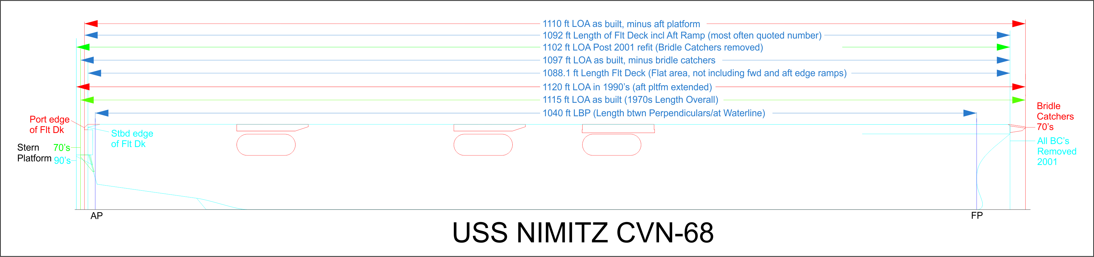
First, there are several Lengths that are often interchanged concerning Carrier lengths. Including Length Overall, Length of horizontal flight deck, Length of flight deck including rounded/sloped ends, etc.
Second, LOA changes whenever something is added or removed from each end, Like Bridle catchers and sponsons.
Safety nets are not typically included in length measurements, but any structures are.
The Hull has never been lengthened.
This diagram of the Nimitz shows how it's length has changed over the years. Enterprise history is very similar.
Darren (Admiral Hawk)
In the not so tropical climate of the Great White North.
That pp or LBP value must be errenous as it's not how you calculate that value!
Lenght Between Perpendicluars is the distance between the nose at waterline and rudder shaft centreline, but what you shown is plain Waterline Lenght. Or the USN uses the two values interchangebly so to make things even more hectic and confusing?
The forward perpendicular, abbreviated as FP, is a vertical line in the sheer plan that is drawn at the intersection of the DWL, which is often the estimated summer load line and the forward side of the stem.
A corresponding vertical line is drawn at the stern, designated the after perpendicular or AP.
- When there is a rudder post the AP is located where the after side of the rudder post intersects the DWL.
- When there is no rudder post, the AP is drawn at the centerline of the rudder stock, which is the customary location for merchant ships without a well defined sternpost or rudder post.
- In the case of naval ships, it is customary to define the AP at the after end of the vessel on the DWL. Such a location is also sometimes chosen for merchant vessels- especially vessels with a submerged stern profile extending well abaft the rudder.
Darren (Admiral Hawk)
In the not so tropical climate of the Great White North.
The forward perpendicular, abbreviated as FP, is a vertical line in the sheer plan that is drawn at the intersection of the DWL, which is often the estimated summer load line and the forward side of the stem.
A corresponding vertical line is drawn at the stern, designated the after perpendicular or AP.
- When there is a rudder post the AP is located where the after side of the rudder post intersects the DWL.
- When there is no rudder post, the AP is drawn at the centerline of the rudder stock, which is the customary location for merchant ships without a well defined sternpost or rudder post.
- In the case of naval ships, it is customary to define the AP at the after end of the vessel on the DWL. Such a location is also sometimes chosen for merchant vessels- especially vessels with a submerged stern profile extending well abaft the rudder.
Erm... then why ww1 and ww2 warships had 3 lengthts not just 2? Your definition mixes waterline and perpendicular length!
What I learned that the pp is fixed except if the hull is changed like the modernizations of the IJN Capital ships.
WL is the length at waterline in standard condition and could change as equipment added for example Iowa had different wl lengths at ww2 and at modern times.
OA is mostly fixed and changes if equipment or modifications were done at the ship ends or to the the entire hull. For example the Clipper or Atlantic bow added to the Bismarcks.
I don't make this stuff up. I refer to published documents.
The USN, and many other Navies, use this approach.
There is a difference between Warships and Merchant ships.
There is a difference between Rounded sterns and Transoms.
Load calculations are different between Merchants and and Warships.
You also have to pay careful attention to wording. FP and AP are used for calculations during initial design. If the waterline changes, the AP and FP may or may not change, I don't know. They are used to define the Stations of a ship when designed. This is different than the frames. I haven't tracked if stations change when load increases. It typically doesn't matter to me.
Anyway, here is an excerpt from a USN training course. I've highlighted the relevant line. If you want to learn more, you'll need to talk to Naval Architects.


