The Ship Model Forum

The Ship Modelers Source
It is currently Sun Jul 27, 2025 9:30 am

All times are UTC - 6 hours [ DST ]


Post new topic Reply to topic  [ 2637 posts ]  Go to page Previous  1 ... 39, 40, 41, 42, 43, 44, 45 ... 132  Next
Author Message
PostPosted: Thu May 15, 2008 12:52 pm 
Offline

Joined: Mon Jan 10, 2005 11:02 am
Posts: 10570
Location: EG48
Essex wrote:
1) If I see well, you have scratchbuilt the deck edge elevator tracks. Is it means, that the kit parts are entirely wrong? Isn't enough to remove the "base plate"?


Check out the photos at the bottom of the damage report for Franklin CV-13's Kamikaze hit. Specifically photos 4526-44 and 4528-44.

_________________
Tracy White -Researcher@Large

"Let the evidence guide the research. Do not have a preconceived agenda which will only distort the result."
-Barbara Tuchman


Top
 Profile  
Reply with quote  
PostPosted: Thu May 15, 2008 2:03 pm 
Offline
Model Monkey
Model Monkey

Joined: Sat Aug 20, 2005 9:27 pm
Posts: 4057
Location: USA
Tracy to the rescue!

Tracy White wrote:
Check out the photos at the bottom of the damage report for Franklin CV-13's Kamikaze hit. Specifically photos 4526-44 and 4528-44.


Tracy's photos beautifully show that the kit's elevator track parts are too simplified. That's why I replaced them entirely. Many modelers use the kit parts and their models look fine that way. I think the real tracks are very interesting structures and decided to try to capture their look better than Trumpy did.

Essex wrote:
The photo on the page 49 in Warships Data 5 shows the modified signal bridge...Do you have some better info (photo, drawing) about this? And what about the...improved funnel cap?


The new bridge and signal deck are features that modelers often miss for 1945 Yorktown. The small bridge and signal deck are correct for 1943-1944. IIRC, Tracy posted photos of USS Franklin CV-13 with the new bridge earlier in this thread. Yorktown's new bridge was identical to Franklin's.

The kit's funnel cap is also simplified. The GMM funnel cap grill parts make the kit look much better. The GMM parts should rest upon a small lip which I included and they should be bowed upward in the middle, not laid flat. Look at some of the other post-refit photos in Warships Data 5 and look at AOTS drawings of the island (E1/1, E5/1, etc.). I'm certain Tracy can suggest other photos of the funnel cap.

Go to the following thread for a explanation of changes I made to my model. I think it answers most of your questions:
viewtopic.php?f=13&t=32648

Essex wrote:
I think the date of the photo on the page 60 isn't March 1945, it must be taken before the 1944 refit because of the earlier "standard" signal bridge.


Yes, the photo on Page 60 is a 1944 photo, not 1945. Look closely at the radars and the position of the port-side hull Bofors mounts which confirm the photo as taken pre-1944 refit. See my build thread for further discussion about this:
viewtopic.php?f=13&t=32648


Attachments:
File comment: You can see the scratch-built elevator track detail in this photo of my as yet
incomplete Yorktown.

IM004139.jpg
IM004139.jpg [ 855.27 KiB | Viewed 1282 times ]

_________________
Have fun, Monkey around.™

-Steve L.

Complete catalog: - https://www.model-monkey.com/
Follow Model Monkey® on Facebook: - https://www.facebook.com/modelmonkeybookandhobby
Top
 Profile  
Reply with quote  
PostPosted: Fri May 16, 2008 6:13 am 
Offline
User avatar

Joined: Wed May 07, 2008 11:04 am
Posts: 29
Location: Budapest, Hungary
Steve Larsen wrote:
Tracy's photos beautifully show that the kit's elevator track parts are too simplified. That's why I replaced them entirely. Many modelers use the kit parts and their models look fine that way. I think the real tracks are very interesting structures and decided to try to capture their look better than Trumpy did.


I see that the Trumpy's elevator tracks are simplified, but I want to know that the outlines of the individual platforms(?) are correct or not? If I want to improve it (or to scratchbuild a new one), I have to know the shape of this platforms.

I know that the edge of these platforms are not perpendicular to the hull, there is a cutout and - if I know well - even a vertical ladder is there just behind the track.

_________________
Sorry for my poor English!


Top
 Profile  
Reply with quote  
PostPosted: Fri May 16, 2008 8:51 am 
Offline
Model Monkey
Model Monkey

Joined: Sat Aug 20, 2005 9:27 pm
Posts: 4057
Location: USA
I think it's best to study photos to get the shape right. I haven't found any drawings that show the supports well enough to model them.

_________________
Have fun, Monkey around.™

-Steve L.

Complete catalog: - https://www.model-monkey.com/
Follow Model Monkey® on Facebook: - https://www.facebook.com/modelmonkeybookandhobby


Top
 Profile  
Reply with quote  
PostPosted: Tue May 20, 2008 1:09 am 
Offline
User avatar

Joined: Thu Jan 17, 2008 4:02 am
Posts: 50
Location: cedar hill, mo
hey guys i'm still working on the ground tackle area of my dragon 1/700 lexington converted to an intrepid. i've got a hopefully easy question(hopefully)that i need answered. on page 68 illistration D2 items #9 and #10. would those hawser reels and the manilla rope reel be duplicated on the other side of the ship? the other side is cut away and the deck plans don't show them.

Image


also would the arched openings#40 be almost to the top of the meatal sheeting between the ground tackle and the front gun tub? or are they more like one level tall like my model has?

Image


i also adjusted the upper deck above the ground tackle to square it off. thanks for the tip off to this area. i'd have probably missed it if it wasn't pointed out. tell me what you think.

Image

_________________
i love it when a plan comes together

it's better to be loved for what you are then to be hated for what you're not


Top
 Profile  
Reply with quote  
PostPosted: Tue May 20, 2008 12:04 pm 
Offline
User avatar

Joined: Wed May 07, 2008 11:04 am
Posts: 29
Location: Budapest, Hungary
Steve Larsen wrote:
I think it's best to study photos to get the shape right. I haven't found any drawings that show the supports well enough to model them.


I have found something on the Floating Drydock. There is a "Bu" Plan (Bu-CV9-34, $18) USS RANDOLPH CV15 CLASS 1943 - DECK EDGE ELEVATOR & DETAILS & TRUSSES. Do you know that plan? Maybe there are drawings for the supports...

------------------------------------

:Oops_1:

I think there is a very large inaccuracy at the 1/350 Trumpy Essex not mentioned yet nor here, neither in the reviews. I have compared the AOTS drawing with the Trumpy hull, and I have found that the height of the hull is the same on the model (1/350 scale) and on the 1/300 scale drawing! It means that the Trumpy Essex is too tall. :frown_2:


Attachments:
File comment: Trumpy's hull compared with the AOTS drawing
AOTS-300_vs_Trumpy-350_a.jpg
AOTS-300_vs_Trumpy-350_a.jpg [ 78.13 KiB | Viewed 1292 times ]

_________________
Sorry for my poor English!
Top
 Profile  
Reply with quote  
PostPosted: Wed May 21, 2008 3:11 pm 
Offline
Model Monkey
Model Monkey

Joined: Sat Aug 20, 2005 9:27 pm
Posts: 4057
Location: USA
raser13 wrote:
would the arched openings#40 be almost to the top of the meatal sheeting between the ground tackle and the front gun tub? or are they more like one level tall like my model has?


Just one level, more like your model.

raser13 wrote:
i also adjusted the upper deck above the ground tackle to square it off. thanks for the tip off to this area. i'd have probably missed it if it wasn't pointed out. tell me what you think.


Looks great!

Essex wrote:
I think there is a very large inaccuracy at the 1/350 Trumpy Essex not mentioned yet nor here, neither in the reviews. I have compared the AOTS drawing with the Trumpy hull, and I have found that the height of the hull is the same on the model (1/350 scale) and on the 1/300 scale drawing! It means that the Trumpy Essex is too tall. :frown_2:


It wouldn't be the first time Trumpeter dorked up an aircraft carrier hull. Trumpy's 1/350 USS Hornet CV-8 hull is really, really, noticeably inaccurately shaped, much worse than their Essex kits. The real Yorktown CV-5 class had very graceful hulls. Trumpy's CV-8 kit hull has been referred to as a "supertanker hull" and rightly so. The perplexing thing is that Revell got the hull shape right on their 1/540 kit decades ago. Trumpy could have simply pantographed that hull and got a better result.

_________________
Have fun, Monkey around.™

-Steve L.

Complete catalog: - https://www.model-monkey.com/
Follow Model Monkey® on Facebook: - https://www.facebook.com/modelmonkeybookandhobby


Top
 Profile  
Reply with quote  
PostPosted: Wed May 21, 2008 3:48 pm 
Offline
User avatar

Joined: Tue Jan 11, 2005 1:40 pm
Posts: 8358
Location: New Jersey
Steve Larsen wrote:
It wouldn't be the first time Trumpeter dorked up an aircraft carrier hull. Trumpy's 1/350 USS Hornet CV-8 hull is really, really, noticeably inaccurately shaped, much worse than their Essex kits. The real Yorktown CV-5 class had very graceful hulls. Trumpy's CV-8 kit hull has been referred to as a "supertanker hull" and rightly so. The perplexing thing is that Revell got the hull shape right on their 1/540 kit decades ago. Trumpy could have simply pantographed that hull and got a better result.


The shame of it is the fit is MUCH better than the fit of the Essex kit!!

_________________
Martin

"Tomorrow is the most important thing in life. Comes into us at midnight very clean. It's perfect when it arrives and it puts itself in our hands. It hopes we've learned something from yesterday." John Wayne

Ship Model Gallery


Top
 Profile  
Reply with quote  
PostPosted: Wed May 21, 2008 10:24 pm 
Offline
User avatar

Joined: Thu Jan 17, 2008 4:02 am
Posts: 50
Location: cedar hill, mo
thanks steve for the info and the input. but does anyone know if the hawsereels and the manilila rope reel are on the starboard side of the ship as well. or are they only on the port side like shown in the diagram? i have already installed the ones on the port side. these is the only sticking points left on this area of the ship,minus railings and ladders.(waiting patiently for those to arive in the mail)

_________________
i love it when a plan comes together

it's better to be loved for what you are then to be hated for what you're not


Top
 Profile  
Reply with quote  
PostPosted: Wed May 21, 2008 10:36 pm 
Offline

Joined: Mon Jan 10, 2005 11:02 am
Posts: 10570
Location: EG48
I found Intrepid's sail yesterday as well as some pictures that should be helpful :) Give me a week or so to get them posted.

_________________
Tracy White -Researcher@Large

"Let the evidence guide the research. Do not have a preconceived agenda which will only distort the result."
-Barbara Tuchman


Top
 Profile  
Reply with quote  
 Post subject: Re:
PostPosted: Thu May 22, 2008 5:39 am 
Offline
User avatar

Joined: Wed May 07, 2008 11:04 am
Posts: 29
Location: Budapest, Hungary
From the page 1 (Tracy, CV-13):

Tracy White wrote:
Here's another picture for those making later-war Essex ships. When the extra quad 40mm mounts were added on the aft starboard quarter, clipping rooms were also added where the ammo could be prepared. The exact details tended to vary from ship to ship, so consult your references or be prepared to make an educated guess. But from what I've seen, in most cases one of the roller doors in this area was removed and the clipping room installed outboard of its location. Another was installed aft of the crane, and both are visible as the small white blocks in the below picture:


From the page 42 (Steve, CV-10):

Steve Larsen wrote:
While studying other Essex class photos, it appears that I may have closed
the wrong roller door near the starboard aft Bofors tubs. Doh. Instead of
closing off the fore-most door of the three short doors, I should have closed
off the aft-most door. Tracy, please confirm. If so, well, that'll give me
something new to fix.


I would like to ask if it looks like on the Yorktown as on your Franklin? On the photos from Yorktown in year 1943 this third door is unambiguously open (we can see through, but on the drawing in Warship's Data 5 this door is not there), on later photos I can't decide, this part is in the shadow. Are the clipping rooms in the same position and have the same shape? I'm building the Yorktown as she looks like after her October 1944 refit...

Tracy, is your Franklin ready for action ot still in progress? :big_grin:

_________________
Sorry for my poor English!


Top
 Profile  
Reply with quote  
PostPosted: Thu May 22, 2008 10:27 pm 
Offline
User avatar

Joined: Mon Jan 17, 2005 8:57 am
Posts: 237
Location: Chesapeake, Virginia
Essex wrote:
I think there is a very large inaccuracy at the 1/350 Trumpy Essex not mentioned yet nor here, neither in the reviews. I have compared the AOTS drawing with the Trumpy hull, and I have found that the height of the hull is the same on the model (1/350 scale) and on the 1/300 scale drawing! It means that the Trumpy Essex is too tall. :frown_2:


Not necessarily. Note that the waterline depiocted on the AOTS drawing might not be the same as where the upper-to-lower hull split occurs on the kit. As a 'for instance', the AOTS drawing might show the ship at full load (i.e., at the top extreme of the boot topping), while the kit's upper half might include some boot-topping for aesthetic or other reasons.

Consider too that the full and light load lines (i.e., the extremes of the boot topping) can change over the course of the ship's life as shipalts add or remove weight.

_________________
Andrew P, PBFHS
Chesapeake, Virginia
www.PBFHS.org


Top
 Profile  
Reply with quote  
PostPosted: Fri May 23, 2008 4:12 am 
Offline
User avatar

Joined: Wed May 07, 2008 11:04 am
Posts: 29
Location: Budapest, Hungary
AndrexP wrote:
As a 'for instance', the AOTS drawing might show the ship at full load (i.e., at the top extreme of the boot topping), while the kit's upper half might include some boot-topping for aesthetic or other reasons.


It's OK, but in this case the height of the armor belt above the waterline and the position of the recessed mooring line choks should be different, and IIRC these are the same on the model as on the drawing. The distance between the hangar deck and the flight deck is about the same, too.

_________________
Sorry for my poor English!


Top
 Profile  
Reply with quote  
PostPosted: Fri May 23, 2008 8:41 am 
Offline

Joined: Mon Jan 10, 2005 11:02 am
Posts: 10570
Location: EG48
That wouldn't be the first Essex kit that Trumpeter had the waterline wrong on... their Arizona kit's way off, but that may be as much from how they had to break it apart for molding as anything.

_________________
Tracy White -Researcher@Large

"Let the evidence guide the research. Do not have a preconceived agenda which will only distort the result."
-Barbara Tuchman


Top
 Profile  
Reply with quote  
PostPosted: Sun May 25, 2008 7:06 pm 
Offline

Joined: Mon Jan 10, 2005 11:02 am
Posts: 10570
Location: EG48
Another researcher at San Bruno knew I was working on Essex class stuff and brought a photo she came across to my attention... unfortunately it was not the best reproduction but I thought I'd include it here; it's a photo of Intrepid's elevator being removed post-war... but it shows a little bit of the underside structure detail for everyone:


Attachments:
IMG_7890.jpg
IMG_7890.jpg [ 92.4 KiB | Viewed 1365 times ]

_________________
Tracy White -Researcher@Large

"Let the evidence guide the research. Do not have a preconceived agenda which will only distort the result."
-Barbara Tuchman
Top
 Profile  
Reply with quote  
PostPosted: Mon May 26, 2008 12:57 am 
Offline

Joined: Mon Jan 10, 2005 11:02 am
Posts: 10570
Location: EG48
Another Intrepid post; I fast-tracked a report by her Captain detailing steering after her February Torpedo hit. It contains two photos of the sail, enough to show that there was NOT one sail, but two. It also shows that there have been some misconceptions being spread for many years about this sail and what Intrepid's sailors did to get her home. A must-read for anyone interested in the history of USS Intrepid.

_________________
Tracy White -Researcher@Large

"Let the evidence guide the research. Do not have a preconceived agenda which will only distort the result."
-Barbara Tuchman


Top
 Profile  
Reply with quote  
PostPosted: Mon May 26, 2008 2:01 pm 
Offline
User avatar

Joined: Thu Jan 17, 2008 4:02 am
Posts: 50
Location: cedar hill, mo
Tracy White wrote:
Another Intrepid post; I fast-tracked a report by her Captain detailing steering after her February Torpedo hit. It contains two photos of the sail, enough to show that there was NOT one sail, but two. It also shows that there have been some misconceptions being spread for many years about this sail and what Intrepid's sailors did to get her home. A must-read for anyone interested in the history of USS Intrepid.


HOLY CR*P! it's amazing what these guys could come up with at sea! reverting to sails for an aircraft carrier,using the planse as a sail, reverting to stars to steer and set course, and that jurry rigged rudder pure genious!

on a good note i now have some good refernce pics of the ground tackle area :woo_hoo: but no one as yet has told me if the hawser reels and the rope reels on the ground tackle were repeated on the right side of the ship or if they were just on the left side? also in the picture of the ground tackle area, inbetween the wildcats there is a structure going from the ground tackle deck to the bottom of the flight deck. what is it? it's not on any of the diagrams in the AOTS.(pictured below circled in red)

Image


also how do you guys do the thumbnails in the messages? is all i can get to work is links and inline images.

_________________
i love it when a plan comes together

it's better to be loved for what you are then to be hated for what you're not


Top
 Profile  
Reply with quote  
PostPosted: Mon May 26, 2008 7:31 pm 
Offline
Model Monkey
Model Monkey

Joined: Sat Aug 20, 2005 9:27 pm
Posts: 4057
Location: USA
Tracy, thanks for the photos above!

Timm, great work on your model. It's really a fine build.

raser13 wrote:
also in the picture of the ground tackle area, inbetween the wildcats there is a structure going from the ground tackle deck to the bottom of the flight deck. what is it? it's not on any of the diagrams in the AOTS.(pictured below circled in red)


It's a structural H-column, called a "flight deck support girder" in AOTS. In the photo above, there are objects strapped to its fore and aft side. The column appears in AOTS in drawings A17/1 and D2. There are three, number "12" in AOTS D2.

You can see some more progress on my 1945 Yorktown. It includes a bit of work in the ground tackle area:
viewtopic.php?f=13&t=32648&p=222316#p222316

_________________
Have fun, Monkey around.™

-Steve L.

Complete catalog: - https://www.model-monkey.com/
Follow Model Monkey® on Facebook: - https://www.facebook.com/modelmonkeybookandhobby


Top
 Profile  
Reply with quote  
PostPosted: Mon May 26, 2008 11:00 pm 
Offline

Joined: Mon Jan 10, 2005 11:02 am
Posts: 10570
Location: EG48
Essex wrote:
That interests me too, I was waiting for Tracy's answer, but maybe it's a top secret? :cool_1: Or you got an answer in a mail? There are some drawings in the Raven's book, but all are different.
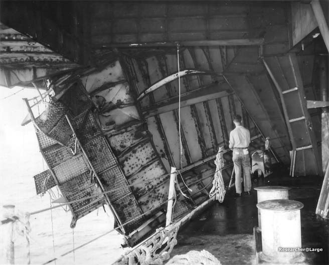

Not top secret at all, it's just that I really don't have any research sources beyond you guys other than the national archives material I've scanned in.... and it's not like that material is anywhere near complete.

Additionally, I don't want to be the only one answering questions here, our goal with the CASF section was to build up a wealth and community of knowledge, and we want to allow and foster others to step up and help as well.

For what it's worth, that photo is the first I've found of this area, port or starboard, from that vantage point.

_________________
Tracy White -Researcher@Large

"Let the evidence guide the research. Do not have a preconceived agenda which will only distort the result."
-Barbara Tuchman


Top
 Profile  
Reply with quote  
PostPosted: Tue May 27, 2008 5:59 am 
Offline
User avatar

Joined: Wed May 07, 2008 11:04 am
Posts: 29
Location: Budapest, Hungary
Tracy, I think that the object on the linked photo (on the right side, attached to the girder) is one of the manilla rope reels, but it seems other than on the AOTS drawing.

http://www.researcheratlarge.com/Ships/CV12/IX.jpg

_________________
Sorry for my poor English!


Top
 Profile  
Reply with quote  
Display posts from previous:  Sort by  
Post new topic Reply to topic  [ 2637 posts ]  Go to page Previous  1 ... 39, 40, 41, 42, 43, 44, 45 ... 132  Next

All times are UTC - 6 hours [ DST ]


Who is online

Users browsing this forum: No registered users and 26 guests


You can post new topics in this forum
You can reply to topics in this forum
You cannot edit your posts in this forum
You cannot delete your posts in this forum
You cannot post attachments in this forum

Jump to:  
Powered by phpBB® Forum Software © phpBB Group