The Ship Model Forum

The Ship Modelers Source
It is currently Fri Apr 19, 2024 10:52 am

All times are UTC - 6 hours [ DST ]


Post new topic Reply to topic  [ 165 posts ]  Go to page Previous  1, 2, 3, 4, 5 ... 9  Next
Author Message
PostPosted: Tue Feb 15, 2011 9:39 am 
Offline
User avatar

Joined: Mon Jan 10, 2005 10:46 am
Posts: 2411
Location: Hoboken, NJ
Beautiful work. I keep thinking I'll teach myself Rhino 3D (I even bought the software), but it just seems a bit beyond my "free time capabilities". I'd love to be able to do some ironclads in 3D, though.

_________________
We like our history sanitized and theme-parked and self-congratulatory, not bloody and angry and unflattering. - Jonathan Yardley


Report this post
Top
 Profile  
Reply with quote  
PostPosted: Tue Feb 15, 2011 7:02 pm 
Offline

Joined: Thu Apr 28, 2005 8:46 pm
Posts: 201
Thanks Devin. I greatly admire your work, especially the Weehawken http://www.devinjpoore.com/models/weehawken/index.htm#4. Re Rhino3D, in the NY area there are two resources I know of for coursework. One is FIT, which is essentially across the street from Penn Station. They teach a course in Rhino for Jewelry, but I think it may be a little higher priced than the standard Rhino Level I course at other venues. The other possiblity is in Brooklyn. http://www.magneticvisions.com/Level1.htm. Never been over there, but I believe the Level I course is standardized. I took Level I in Miami, and I recommend it. Taking the 3-day course is the fastest way to pick up the program.

Rhino3D is a little wasted on ironclads. It is great for producing compound (voluptuous) curved shapes, e.g. aircraft fuselages, yacht hulls, and sports racing cars. However, doing an ironclad is a perfect project if you want to pick up the basic skills. McNeel publishes a DVD called Visual Tips 4.0. They gave it to us when we took Level I, so don't buy it if you plan to take the course. However, it is a good vehicle for self study. Finally, there are quite a few tutorials on the web. Some are referenced on the McNeel site. http://wiki.mcneel.com/rhino/tutoriallinks
Michael


Report this post
Top
 Profile  
Reply with quote  
PostPosted: Mon Feb 21, 2011 12:43 pm 
Offline
User avatar

Joined: Mon Jan 10, 2005 10:46 am
Posts: 2411
Location: Hoboken, NJ
Michael,

Thanks for the info and the compliment on the Weehawken. If I build another Passaic class there are a few things I'll do differently, but I'm happy with Weehawken and have her mounted on the wall right above my computer.

My interest in Rhino would mostly be for the lower hulls of these things. I really want to scratch a model of a Canonicus class, and I can do the upper hull and turret almost with my eyes closed, but the lower hull is a problem. I have hull lines, but no stations, and I'm not ready to tackle a bread-and-butter build just yet. With Rhino I'd be able to muck around, get things to work, and save a lot of time, headache, and dust.

I'll check out those classes. Thanks.

-Devin

_________________
We like our history sanitized and theme-parked and self-congratulatory, not bloody and angry and unflattering. - Jonathan Yardley


Report this post
Top
 Profile  
Reply with quote  
PostPosted: Sat Feb 26, 2011 6:17 pm 
Offline

Joined: Thu Apr 28, 2005 8:46 pm
Posts: 201
Yes, I see what you mean. It should work nicely. From Maryland Silver I have a roll of plans from the National Archives for the Dictator, and the hull for that Monitor is very modern and hydrodynamic looking. The Canonicus hulls may be similar -- should look great.

Working on framing. This is a cast iron bracket that is deeply mortised into, and through-bolted to, each oak deck beam.
Attachment:
bracket x 70 small.jpg
bracket x 70 small.jpg [ 64.15 KiB | Viewed 6067 times ]
To the bracket are bolted a vertical stanchion that extends straight down to a floor timber, and a diagonal brace that runs out to ship's armored sidewall. This bracket is a recurring element in Ericsson's design. There were 70 of them, two on each deck beam, 35 on each side of the ship.

If you hammer away at CAD on the USS Monitor for long enough, you may notice that Ericsson had a design mannerism: he liked to make things 17-inches wide or deep. The sheet iron webs that support the turret shaft are 17 inches deep. These brackets are 17 inches wide. Where you or I might use 18 inches as a default for something that needs to be the the next size up from a foot, John Ericsson favored 17 inches.

The bracket casting is in the shape of a tray, with ridges that project upward from its upper surface.
Attachment:
mortised into oak beam small.jpg
mortised into oak beam small.jpg [ 27.91 KiB | Viewed 6067 times ]
If we peer inside the oak beam, it is clearer how these brackets were mortised into the wood. I don't know if they had power routers, or if they used chisels. But with so many of these brackets, I would guess the beams were grooved for the brackets using jigs, as a milling process before the beams were mounted.

Another guess would be that the bolt heads on top of the beam were immobilized -- molded or cemented into place with tar or something like that. After the pine deck went on, there would be no way to put a socket wrench on them. Here is a rendered version.
Attachment:
repeating element small.jpg
repeating element small.jpg [ 43.43 KiB | Viewed 6066 times ]
Nuts and bolts TK.

Take two. A closer look at the original drawing shows the bracket was secured with 2-inch square bolt heads. There is no top view, but the word "square" is handwritten on the front view. These square boltheads were mortised into the tops of the deck beams. They looked like this:
Attachment:
take two small.jpg
take two small.jpg [ 41.58 KiB | Viewed 6050 times ]
No cement, no tar. Simple solution.
Attachment:
square boltheads small.jpg
square boltheads small.jpg [ 27.93 KiB | Viewed 6043 times ]


Report this post
Top
 Profile  
Reply with quote  
PostPosted: Sun Mar 06, 2011 6:46 pm 
Offline

Joined: Thu Apr 28, 2005 8:46 pm
Posts: 201
Here are 10 of the monitor's frames, aft of the central bulkhead. The "floor timbers" each consist of a 12-inch high sheet of half-inch thick iron. This sheet is turned into a C-beam by angle irons riveted to the top and bottom edges. These were 4" by 4" and nicely filleted to avoid concentrations of stress.
Attachment:
Monitor framing small.jpg
Monitor framing small.jpg [ 61.59 KiB | Viewed 6028 times ]
The flanges projected aft. A planked wooden deck (not shown) was laid over the floor timbers. The diagonal pieces rising from the floor timber were 3" by 6" angle iron -- Ericsson called these "the ribs." Note his use of stanchions in triangulating the framework. These were not tubes but solid iron columns 2.75 inches in diameter.

What appear to be lightenng holes in the floor timbers were actually ventilation ports.

Forward of the central bulkhead the framing was basically the same, except that the floor timbers were taller -- 15 inches instead of 12 inches. Possibly this is because in the aft half of the ship there were pipes and machinery mounted to the ceiling. To make more headroom, the designer may have decided to lower the floor.

Altogether there were 35 of these frames, spaced at 36" intervals.

At the peak of construction activity, in the winter of 1861-62, Rowland had 175 men working 24/7 on the Monitor. The turret and the engines were built by other New York yards -- Novelty and Delamater -- so Rowland's Continental crew was basically building the ship.

Structures like this one would probably be a little tedious to model on the workbench but they are not so bad in CAD, thanks to Mirror and Array commands. I drew 1/2 of one of these frames, then mirrored it, then replicated it.


Report this post
Top
 Profile  
Reply with quote  
PostPosted: Mon Mar 07, 2011 9:48 am 
Offline
User avatar

Joined: Mon Jan 10, 2005 10:46 am
Posts: 2411
Location: Hoboken, NJ
Outstanding work. I really love the structural deatils of these old ships, and you're doing a great job of replicating them.

Question: I've been doing some casual searching for the "Drawings of the USS Monitor" book, and coming up with nothing. Where did you get your copy?

_________________
We like our history sanitized and theme-parked and self-congratulatory, not bloody and angry and unflattering. - Jonathan Yardley


Report this post
Top
 Profile  
Reply with quote  
PostPosted: Mon Mar 07, 2011 12:48 pm 
Offline

Joined: Thu Apr 28, 2005 8:46 pm
Posts: 201
Mine was on Abebooks.com, and until fairly recently they had three copies available. Now there are none listed. It is an important book -- probably the definitive work on the Monitor -- but it was produced by a government printing office. I wish they would reprint it. I watched for it for it to surface for a long time and I was kind of amazed when I actually discovered a copy. Keep an eye on Abebooks.com or a metasearch engine like Bookfinder and when a copy comes up for sale, pounce. If there is some structure you are interested in let me know via pm and I will send you a scan or a .3dm.


Report this post
Top
 Profile  
Reply with quote  
PostPosted: Mon Mar 07, 2011 1:05 pm 
Offline
User avatar

Joined: Mon Jan 10, 2005 10:46 am
Posts: 2411
Location: Hoboken, NJ
Ah, I will keep an eye open. Thanks. I had to do that for my copy of Canney's "The Old Steam Navy" ironclads volume. It took about 6 months, but I found one on eBay from a guy in England that evidently didn't know what he had, and I got it for about 1/3rd of the going price.

I'm not looking for anything in particular at the moment, but thanks for the offer. I have an old soft-bound book that is a catalog of the original Monitor drawings; each page is a reduced photo of the drawing, and annotations of who has the original. I used that for a lot of ideas on my Weehawken build.

_________________
We like our history sanitized and theme-parked and self-congratulatory, not bloody and angry and unflattering. - Jonathan Yardley


Report this post
Top
 Profile  
Reply with quote  
PostPosted: Mon Mar 07, 2011 8:42 pm 
Offline

Joined: Thu Apr 28, 2005 8:46 pm
Posts: 201
This is what "Drawings" looks like. It has two color illustrations -- the cover and a fold out. Possibly this the book you already have.http://www.amazon.com/Drawings-U-S-S-Mo ... =1-2-spell


Attachment:
Stanchions small.jpg
Stanchions small.jpg [ 60.59 KiB | Viewed 5986 times ]
Row of stanchions viewed from the forward end of the frame stack. Endlessly repeated cast iron brackets. There is something oddly robotic about them.


Report this post
Top
 Profile  
Reply with quote  
PostPosted: Mon Mar 07, 2011 8:58 pm 
Offline
User avatar

Joined: Mon Jan 10, 2005 10:46 am
Posts: 2411
Location: Hoboken, NJ
That's hilarious. That is the exact book I have. I haven't "seen" it in a few months, though, (moving stuff around the house), so I didn't remember who wrote it.

Several of the drawings in that book are listed as being in the collection of Steven's University, right here in Hoboken. I intend to see if I can get in to see them someday.

_________________
We like our history sanitized and theme-parked and self-congratulatory, not bloody and angry and unflattering. - Jonathan Yardley


Report this post
Top
 Profile  
Reply with quote  
PostPosted: Tue Mar 08, 2011 7:48 am 
Offline

Joined: Tue Jan 11, 2005 7:44 pm
Posts: 836
Location: Zipangu - Jipukuo
http://www.youtube.com/watch?v=maXBBQe1928

Sorry...couldn`t resist! I`ve always been curious as to why Hoboken NJ was such a vex for Bugs Bunny. :big_grin:

_________________
No Quarter Asked - None Given
Image


Report this post
Top
 Profile  
Reply with quote  
PostPosted: Sat Mar 19, 2011 9:27 pm 
Offline

Joined: Thu Apr 28, 2005 8:46 pm
Posts: 201
We have a couple of overhead views of the crankcase for the V-twin turret engine, but the side views are incomplete or unclear. So basically we start from a 2D overhead view. The best one we have (Peterkin #176, Stevens McCord collection No. 30/124) is a rough draft, with several crossings out, erasures, overdrawings and redrawings. Accordingly, there are several possible 3D interpretations of how the turret drive crankcase looked and worked. Here are five mocked up possibilities:
Attachment:
File comment: 2D shows at least one curved shelf -- but why, where and how many?
permutations small.jpg
permutations small.jpg [ 41.96 KiB | Viewed 5908 times ]


In this circumstance, you can only ask yourself, how should this thing work? And try to guess the most reasonable approach.

Here are some design criteria for the crankcase:

1) It must be possible to assemble it. Put another way, there must be some means for getting the crank into the crankcase.
2) The crankcase requires adequate clearance to swing two connecting rods. We have one partial overhead sketch of one of these con rods, and some circles and lines Ericsson pulled to show their range of motion.
3) It requires adequate room for the valve gear drive, which consists of two eccentrics driving two rods to actuate the valves.
4) The crankcase must stabilize the crank and the pinion against very considerable reversing loads. For this reason I think it needed a middle bearing between the crank and the pinion.

Here is my current guess at the structure of the crankcase.
Attachment:
Installed crank - small.jpg
Installed crank - small.jpg [ 21.23 KiB | Viewed 5941 times ]

One assumption is that the crank pin could be locked and unlocked. According to a handbook on 19th century steam engine practices, this was a fairly common mechanical feature.

It appears from the drawings that Ericsson provided simple (un-split) thrust bearings at the top and bottom of the crank, inset or simply cast into the basic box. In the middle of the crank, between the crank and the pinion gear, I am guessing there was a bearing set into a web. This central web would work very like a crankcase web you would find if you dropped the pan of a modern IC engine. At this middle web, there would have been a cap secured with bolts -- a split bearing surface. All three bearings could be align-bored.
Attachment:
split bearing small.jpg
split bearing small.jpg [ 38.19 KiB | Viewed 5930 times ]

To install the crank, the lower half would have been positioned in the bottom and web bearings. The upper component of the crank could then be loosely mounted on the crankpin, and rotated into the box. It could then be slid upward along the crankpin so that the crank axle seated in the upper thrust bearing. The crankpin would then be locked or pinned in place. and the split middle bearing completed with a bolted cap.

The open box structure of this crankcase allows sufficient clearance to rotate the ends of two connecting rods.

Above the crank, it appears there would be room enough for two cams, each driving a valve of the V-twin steam cylinders. These cams certainly exist, but it is not clear from the drawing where on the shaft – up or down or in the middle -- the cams were positioned. They appear only in an overhead view (Peterkin #13, Stevens McCord collection No. 14). I’d like to put them on the upper part of the crank because there seems to be room for them there, and because this positioning gives the valve rods a reasonably direct path to the valve linkage.

Clearance looks adequate for the two valve rods to rotate on their eccentrics. So this mock-up looks plausible, but to see whether this type of crankcase could actually work, I will need to fill in the cams, the valve gear and the connecting rods.


Report this post
Top
 Profile  
Reply with quote  
PostPosted: Tue Mar 22, 2011 9:50 am 
Offline
User avatar

Joined: Fri Aug 04, 2006 12:03 pm
Posts: 125
Location: Salem, MA, USA
MCG,

Looks like a reasonable method. Some very nice investigative thinking. I assume that the split bearings would be grease lubricated brass liners?

_________________
Best Regards

Fritz K.


Report this post
Top
 Profile  
Reply with quote  
PostPosted: Tue Mar 22, 2011 3:25 pm 
Offline

Joined: Thu Apr 28, 2005 8:46 pm
Posts: 201
I welcome your ideas on this. The books I have often refer to bearings as "the brasses", so it would make sense if these were brass. How the grease was applied or injected is not clear to me. No zerks or pressure fittings that I can see -- maybe they had not yet been invented. The deck bearing box for the turret had four deep grooves cut into its upper surface to retain grease. Maybe they had in fact invented the grease gun for use, for example, on prop shafts, locomotives, mills or stationary engines. Michael


Report this post
Top
 Profile  
Reply with quote  
PostPosted: Tue Mar 22, 2011 7:05 pm 
Offline
User avatar

Joined: Fri Aug 04, 2006 12:03 pm
Posts: 125
Location: Salem, MA, USA
Hi Micheal

Yes Zerks were not invented until 1929. Prior to that there were a couple of other methods. The simplest (for intermittent use) was simply several longitudinal channels in the brass. Grease would be slathered on at each end and allowed to work its way along the channels and onto the bearing surface. For continuous use bearings, there would be a oil hole, or fill drilled from outside to somewhere to the middle of the oil grooves. Then either an oiler would come around periodicaly with his oil can and manually add oil at determined time intervals to keep the bearing from running dry. Later, some machinery started to be fitted with what was called a Lunkenheimer oiler; A reservoir that allowed for less regular visits by the oiler.

_________________
Best Regards

Fritz K.


Report this post
Top
 Profile  
Reply with quote  
PostPosted: Wed Mar 23, 2011 6:34 am 
Offline

Joined: Thu Apr 28, 2005 8:46 pm
Posts: 201
Thank you, Fritz, this is very helpful. From the Mariner's museum I have ordered a computer enhanced image of the USS Monitor and I will scrutinize it for additional detail on the oiling/greasing system. Some means of lubrication has to be there. On Rich Carlstedt's faithful scale model of the main USS Monitor engine, there appear to be brass oiling cups or reservoirs mounted on or above some of the bearings, much like those you are describing.

http://www.youtube.com/watch?v=VWn8gQ9Ykpk

Four greasing channels like those you describe are arrayed in a cruciform pattern on the main turret bearing.
Ericsson was consistent in his design work, and techniques and solutions he used in one application may turn up in other machinery on the ship. However, the two turret drive engines were bought off the shelf from a vendor, Clute Brothers, so they are not Ericsson designs. He did, however, custom design this crankcase for them.

Update. The computer enhanced image has now come in from the Mariner's Museum. My speculation that the crankcase had three tiers now seems very unlikely. There isn't enough room between the pinion and the crank for a third bearing. So the likelier crankcase, in light of the new SIDE image, is a simple box with just two bearings.
Attachment:
likelier crankcase small.jpg
likelier crankcase small.jpg [ 47.27 KiB | Viewed 5837 times ]


Report this post
Top
 Profile  
Reply with quote  
PostPosted: Sat Apr 16, 2011 7:57 pm 
Offline

Joined: Sat Apr 16, 2011 7:31 pm
Posts: 33
Wow that's a neat project. I've also tried to find the Peterkin book, to no avail - one post on another forum indicated that the organizations the originally published it don't even seem to remember doing so, so that doesn't bode well for a reprint...

One possibility, which I can't verify without having the book to check - is the book under copyright? It sounds like some sort of government sponsored effort, although I guess North Carolina played a roll too... if it isn't subject to copyright perhaps someone who does have a copy could send it to Google to have them scan it for Google Books?

I've hunted for information on the Monitor before - my interest is in finding public domain information suitable for construction of open source CAD models, and it's surprisingly difficult to find suitable material (even if its out of copyright, museums often want to restrict publication on copies) - and what little is online often seems to be very low resolution scans. One time at the national archives I did manage to get copies of a couple drawings for the USS Monadnock (somewhat deceptively called "the 1st monitor", so not quite what I was expecting) but they didn't seem to have anything like the collection in the Peterkin book.

In case the Monadnock interests anyone the images are here:
http://bzflag.bz/~starseeker/National_A ... -large.png
http://bzflag.bz/~starseeker/National_A ... scaled.png


Report this post
Top
 Profile  
Reply with quote  
PostPosted: Sun Apr 17, 2011 10:36 am 
Offline
User avatar

Joined: Sun Mar 07, 2010 12:01 am
Posts: 1645
Location: Corvallis, Oregon, USA
Michael,

I have been thinking about lubrication of the bearings. It was common practice up into the 20th century to lubricate bearings just with oil. The fireman's oilcan is an icon for the steam locomotive era. Every time the locomotive stopped he made the rounds to lubricate all of the moving parts.

Likewise, one of the duties of the black gang on ships was to make the rounds and oil bearings on a regular schedule. This not only gave the watch crew something to do to keep them awake, but it also ensured frequent observations of how the machinery was running.

Of course, even modern automobile and aircraft engines still lubricate crankshaft bearings with oil.

So I suspect there was something like the oil cups you mentioned on the model engine.

Phil

_________________
A collision at sea will ruin your entire day. Aristotle


Report this post
Top
 Profile  
Reply with quote  
PostPosted: Sun Apr 17, 2011 5:22 pm 
Offline

Joined: Thu Apr 28, 2005 8:46 pm
Posts: 201
Thanks Phil. It makes sense. Most of it was probably oiled, and oil cups are evident in the drawing just supplied by Starseeker. The deck bearing, however, shows channels for grease. It is curious that the turret drive crankcase was mounted directly over the galley stove. I have wondered if maybe this was deliberate -- a way to heat up (and loosen up) the whole mechanism on a frosty morning. It creates some questions, tho, about dripping oil. I think the crankcase must have had an oil box, or in modern parlance, a sump or pan -- to keep the lubricant from dripping into the pancakes.

Starseeker -- many thanks. That is the best drawing of a monitor turret drive engine I have ever seen anywhere. It shows that in the 1864 engine there was an unusual valve gear that worked without cams. So the question arises: Did the 1861 USS Monitor turret engine have this same, rather exotic type of camless valve system?

Everyday 19th century steam engines commonly used eccentric sheaves and cams to time the valves.

Here is photo from "Steam on the water", a blog by a steam enthusiast that shows some typically Victorian eccentric sheaves.
http://2.bp.blogspot.com/_irmB-ntBP9o/T ... heaves.JPG

Here is a pair of cams and sheaves in action, in an animated valve gear of the Stephenson type.
Image

And here is a simplified application in a typical steam engine with a slide valve.
http://www.mgsteam.btinternet.co.uk/svalve.htm

In an early USS Monitor drawing (Peterkin #13, Stevens #14) eccentric sheaves and cams are clearly present in an overhead view of the turret engine crankshaft. But Peterkin thought this drawing was just a draft or preliminary sketch, and points out several other features that do not appear or change markedly in subsequent drawings.

In any event, the eccentric sheaves and cams disappeared -- vanished completely -- in subsequent drawings of the USS Monitor.

In Starseeker's astonishing drawing of the Monadnock turret engine, we get a hint at what may have happened. It depicts a valve gear and reversing mechanism in which there are no cams nor cam followers.

The valve drive push-and-pull for each cylinder's slide valve is picked up (borrowed, in effect) from the crosshead of the other cylinder in the V-twin. This works because the two cylinders are locked 90 degrees out of phase.

This type of camless valve drive is usually attributed to Otis W. Young, who patented it for use in steam locomotives in the 1920s. Apparently Ericsson or some other inventor in the 1850s or 1860s had already visited this very good idea.

As for the USS Monitor of 1861-2 it is hard to guess whether or how much of the 1864 Monadnock technology applied. In the USS Monitor we have the mysterious absence of cams and sheaves -- they are missing from all but one of the USS Monitor drawings, and that one is thought to have been preliminary. Although "absence of evidence is not evidence of absence," I will probably rely on the camless Monadnock technology from here on.

Eventually the turret drive will come up from underwater, and on that day we can quit guessing how it worked.

Starseeker, thank you again for this huge contribution. Re the copyrights, the Peterkin book is not copyrighted, However, every important drawing in it was reproduced with attribution and specific permission from one collection or another. This is the 150th anniversary of the civil war, a lot of books are coming out for the occasion, and I notice the collections are extremely careful about preserving and marketing their rights. No objections from me. Money raised this way goes to the good causes of diving expeditions, documentation and preservation.
Attachment:
no cam small.jpg
no cam small.jpg [ 32.36 KiB | Viewed 5740 times ]
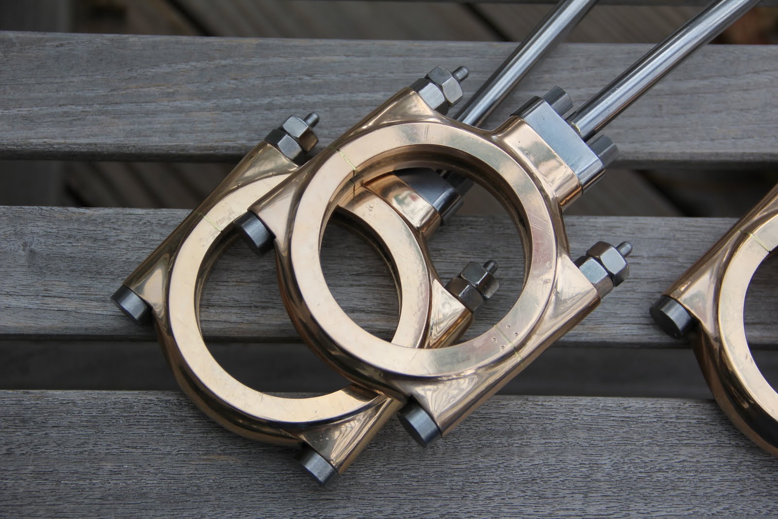
This is one of the eccentric sheaves I was working on. The brass bearing inset is relieved for the cam.
Attachment:
eccentric sheave small.jpg
eccentric sheave small.jpg [ 81.24 KiB | Viewed 5740 times ]
This shows the cam ghosted into place, clamshelled between the two halves of the eccentric sheave, which was also called an eccentric strap. The cams as sketched are 1.5 inches deep, and the USS monitor crankshaft and crankcase are designed with just enough room to stack two of these, one per cylinder. One possibility is that cams were in fact used in the Monitor, and another is that they were discarded around October, 1861, in favor of the much cleverer camless system researched by Starseeker. The whole turret drive apparatus, which Admiral Porter dubbed "the coffee grinder" was installed in the ship at the Continental Iron works in the last week of November, 1861.

I may end up drawing the system both ways, since I have already sketched the cam system. Michael


Last edited by mcg on Mon Jun 06, 2011 6:26 am, edited 2 times in total.

Report this post
Top
 Profile  
Reply with quote  
PostPosted: Wed Apr 20, 2011 3:34 pm 
Offline

Joined: Sat Apr 16, 2011 7:31 pm
Posts: 33
Michael,

You're very welcome - I'm thrilled that the drawing is helpful!

re: Peterkin book - yeah, I'm not surprised the various collections used the permission based system. It was a long shot, but worth checking given how hard it is to find copies of the original. I don't know if the "used by permission" status of the images in the book would preclude digital copying of the book itself if the book as a whole isn't copyrighted, and it's probably not worth the hassle it would take to find out. I don't object to the collections making money to support the ongoing costs of maintaining the collections either, although I do wish sometimes we could find a way to support them while allowing broader access.... I've see only the one indication that the various publishing organizations don't have any recollection of the book. Perhaps we could start some sort of organized effort to get them to republish it and jog their memory? If there's enough demand for it perhaps they'd consider it.

Just curious - what are your plans for your CAD model? Do you plan to release it eventually?


Report this post
Top
 Profile  
Reply with quote  
Display posts from previous:  Sort by  
Post new topic Reply to topic  [ 165 posts ]  Go to page Previous  1, 2, 3, 4, 5 ... 9  Next

All times are UTC - 6 hours [ DST ]


Who is online

Users browsing this forum: No registered users and 21 guests


You can post new topics in this forum
You can reply to topics in this forum
You cannot edit your posts in this forum
You cannot delete your posts in this forum
You cannot post attachments in this forum

Jump to:  
Powered by phpBB® Forum Software © phpBB Group