The Ship Model Forum

The Ship Modelers Source
It is currently Tue May 20, 2025 6:37 am

All times are UTC - 6 hours [ DST ]


Post new topic Reply to topic  [ 29 posts ]  Go to page 1, 2  Next
Author Message
PostPosted: Wed May 29, 2013 2:20 pm 
Offline
User avatar

Joined: Mon Dec 19, 2011 9:11 pm
Posts: 822
Location: Norman, Oklahoma
Greetings everybody! :wave_1:


I am relatively new to modeling, and even newer to 3D CAD modeling. Although I have been using AutoCad for 2D applications for many years, my only experience with 3D has been on two recent projects:

1/144 Scale USS Greenling (SSN-614) – Design completed – “Undetailed” model printed and being constructed, “Detailed” model awaiting printing. I have 2 logs going on this one. Much of the information is the same, but not all of it.

http://www.shipmodels.info/mws_forum/viewtopic.php?f=59&t=125875

http://www.subcommittee.com/phpBB3/viewtopic.php?f=35&t=11272

1/144 Scale USS Batfish (SS-310) – Design underway

http://www.subcommittee.com/phpBB3/viewtopic.php?f=35&t=11272

I am making the Goalkeeper (GK) in exchange for having my parts printed. I thought I would post the process, because I am by no means an expert on ships or weapon systems, and I have learned, from previous experience, that I receive excellent advice and assistance when I post my progress. Many blunders on were averted on Greenling and Batfish by kindly forum members who kept me on track. So, please, if you have experience or knowledge of GKs, and see that I am doing something wrong, or think you know of something I could do to make it better, please let me know. I’m all ears!

Before I start describing what I have done thus far, here are 3 pictures of GKs.

Image

Image

Image

So, here we go…

I started by importing the only plans with dimensions I have into AutoCad…

Image

…And scaling it. I started at full scale, and converted to 1/350 scale later.

Image

I then brought a more detailed, but non-dimensioned set of plans into AutoCad…

Image

…And scaling it as well.

Image

I then drew circles for the base…

Image

…Moved them into position and lofted them. I then did the same for the upper portion of the base…

Image

…And for the turret(?). Note that the turret is off-center, because that is the way it is shown on the plans. The more I thought about it though, the more I realized that it has to be centered, so I moved it later.

Image

Image

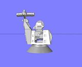
At this point I started on the main body. I made the body by first drawing squares as shown on the plan view of the GK. Using the side views, I determined the lengths (or elevations) of the bottom and top of the body and changed the elevations of the rectangles accordingly.

Image

I then lofted between the two rectangles.

Image

To be continued…

_________________
Completed:
1/350 USS Missouri (BB-63) * 1/350 USS England (DE-635) * "Underway Personnel Transfer" Diorama

In Progress:
1/350 USS Bennington (CV-20)
1/144 USS Greenling (SSN-614) - ACAD/3D Printing
1/144 USS Batfish (SS-310) - ACAD/3D Printing


Report this post
Top
 Profile  
Reply with quote  
PostPosted: Wed May 29, 2013 3:14 pm 
Offline
User avatar

Joined: Mon Dec 19, 2011 9:11 pm
Posts: 822
Location: Norman, Oklahoma
UPDATE 2

To cut out the opening for the gun, I used the front view to trace a rectangle, which I extruded…

Image

…And subtracted.

Image

I next started on the “arm” on the rear left of the body. This was done by simply lofting between two squares, although at first it seemed more difficult than that.

Image

The next section was vertical so I simply copied the rectangle from below up to the correct level and lofted the two of them.

Image

The top part of the arm was the most diifcult to figure out, but in the end it only required properly aligning a smaller rectangle, putting it at the correct elevation and lofting with the rectangle below.

Image

Image

Working my way up, I next created the cylinder at the top of the arm with lofted circles.

Image

The top looked like it might be difficult to figure out, so I had my first go at the gun cages. The image below doesn’t show how I did it very well, but I essentially used the sections on the plans to created rectangles at the proper locations longitudinally, and then centered them on the axis of the barrel group (not present yet).

Image

I then lofted the rectangles…

Image

…And shelled the front portion. (Note: the back portion is on a layer that is turned off.)

Image

Next I created the openings in the top and bottom of the cage. The ones on the plans weren’t too good, so I made my own, using the plans only for horizontal positioning.

Image

I then lofted the resulting rounded triangles…

Image

…And subtracted them.

Image

I did the same for the sides.

Image

Image

Image

Switching to the barrels I started by extruding a circle from the end of the barrel through the rear part. The mage below doesn’t show it but I later had the cylinder sticking out the back side.

Image

Using the section plans I sliced the cylinder up to create the supports for the 7 barrels.

Image

To be continued…

_________________
Completed:
1/350 USS Missouri (BB-63) * 1/350 USS England (DE-635) * "Underway Personnel Transfer" Diorama

In Progress:
1/350 USS Bennington (CV-20)
1/144 USS Greenling (SSN-614) - ACAD/3D Printing
1/144 USS Batfish (SS-310) - ACAD/3D Printing


Report this post
Top
 Profile  
Reply with quote  
PostPosted: Wed May 29, 2013 4:33 pm 
Offline
User avatar

Joined: Mon Dec 19, 2011 9:11 pm
Posts: 822
Location: Norman, Oklahoma
UPDATE 3

Turning my attention to the barrels, I started by using the plans to layout the barrels with circles.

Image

I positioned the top center barrel and then used the polar array command to evenly space the other 6.

Image

I then moved these circle to the center line of the barrel group and rotated it 90 degrees. I then moved the outer blue ring back a bit, and then separately extruded it and the 7 barrel circles. In the pictures I have seen, it looks like there is another support within the cage, so added one there.

Image

Also observed in pictures and on the plans is a block of some sort under the barrels, on the right side (left when looking at it), so I used the plans to trace a polyline, which I then copied down to the base axis.

Image

After rotating it and positioning it correctly, I extruded it.

Image

I then copied the barrel assembly and two gun cage parts to the correct location on the base.

Image

Image

You probably noticed that the GK has a rainbow of colors. I do this because during the early stages of the “build” I keep the individual parts separate because it makes it easier to make changes if need be. Rounding of edges, for example can be a problem after you have joined parts. Since I had the parts separate, I was easily able to round the edges that needed to be rounded. Another thing I do to make changes easier is set delobj to 0, so the geometry is saved. I then copy them to a layer that is usually off but can be turned on if needed to redo something.

Image

After rounding the edges, I decided that it was time to join the parts of the main body. I did so and then started adding detail to the top of the rear section of the gun.

Image

From the beginning, I didn’t like the gun cage that I more or less copied from the plans, which was too flat. If you look at pictures of the cage, it seems to be made out of pipe, so I redid it. This time I made the outer support structure using extruded circles and rounded rectangles for their paths on the ends and lines between the corners for the straight pieces (red). I then lofted two rectangles and shelled the resulting shape (magenta). I also redid the openings because the more I looked at the ones I had, they were also wrong. So I made new triangles and extruded them as shown below.

Image

I then subtracted them and setup to do the same for the sides…

Image

…And subtracted it.

Image

When I was happy with it, I went to the GK itself and deleted the previous barrel cage…

Image

…And copied the new one in its place.

Image

Image

Image

Image

That is where I am to this point and I must say that so far I am happy with it and am having a lot of fun. Redoing the gun cage was worth the extra time, because I think that it looks a lot better. Now, back to the model.

Cheers!!!

_________________
Completed:
1/350 USS Missouri (BB-63) * 1/350 USS England (DE-635) * "Underway Personnel Transfer" Diorama

In Progress:
1/350 USS Bennington (CV-20)
1/144 USS Greenling (SSN-614) - ACAD/3D Printing
1/144 USS Batfish (SS-310) - ACAD/3D Printing


Report this post
Top
 Profile  
Reply with quote  
PostPosted: Thu May 30, 2013 9:38 am 
Offline
User avatar

Joined: Thu Apr 03, 2008 10:48 pm
Posts: 2644
Location: Connecticut, USA
Well it's all chinese to me, but certainly looks pretty awesome! Nice job :thumbs_up_1:

_________________
Enlisted men are stupid, but very cunning and deceitful and bear considerable watching." - Marine Corps Officers Manual, 1894

http://www.modelshipgallery.com/gallery ... index.html


Report this post
Top
 Profile  
Reply with quote  
PostPosted: Thu May 30, 2013 11:26 pm 
Offline
User avatar

Joined: Mon Dec 19, 2011 9:11 pm
Posts: 822
Location: Norman, Oklahoma
Thanks Ryan! Here’s some more Chinese. :smallsmile:

Continuing up the arm, I decided to make the cylinder on the outside of the arm (green). I started by drawing a circle on the rear view section and copying it in place on the left side view.

Image

I lofted it and then made a smaller circle and lofted it too, because the cylinder has two parts, narrower forward, wider aft.

Image

Next I added a blocky section in the middle of the cylinder (red), and the platform for the cylinder (blue)…

Image

…And filleted the edges of the cylinder.

Image

I then added the box on the inside of the arm. This time I traced the outline from the plans…

Image

…Copied it to the proper location with respect to the center line…

Image

…And extruded it.

Image

I then moved it into position against the yellow “shaft”.

Image

Image

At this point I added the flange shown in pictures (but not the plans) at the top of the body where the arm juts out.

Image

Most of the remaining parts of the arm were designed from pictures rather than the plans, including two flanges added at the top of the yellow “shaft”. The bottom of the antenna support was also adlibbed from pictures, lofting between rectangles to match the shape observed.

Image

The end was sliced off and the edges rounded.

Image

Continuing upwards, the cylindrical and conical sections of the antenna support were added by lofting circles. A transition section was also added. The aft end edges were rounded.

Image

Next, I used the plans to size the antenna itself, and rounded the edges on the end.

Image

At this point I redid the spherical and conical sections and the transition to make it slightly larger , and added features up top to better match the photographs than the plans do.

Image

I then recolored everything light grey to get a better idea of what it will look like. Besides the lower flange on the arm, which I attached to the arm, the remaining components are not attached, in case I need to make corrections.

Image

Image

CHEERS!!!

_________________
Completed:
1/350 USS Missouri (BB-63) * 1/350 USS England (DE-635) * "Underway Personnel Transfer" Diorama

In Progress:
1/350 USS Bennington (CV-20)
1/144 USS Greenling (SSN-614) - ACAD/3D Printing
1/144 USS Batfish (SS-310) - ACAD/3D Printing


Report this post
Top
 Profile  
Reply with quote  
PostPosted: Fri May 31, 2013 11:42 am 
Offline
User avatar

Joined: Mon Dec 19, 2011 9:11 pm
Posts: 822
Location: Norman, Oklahoma
UPDATE 5

Hi guys!

I got a lot done last night, even though upon inspection this morning, some of it will need to be redone. I started with the radar, first tracing the outline of the cone from the drawings…

Image

Image

…Then rounding the nose…

...And then revolving it.

Image

Although not shown on the plans, pictures reveal that the backside is convex, so I adlibbed it.

Image

From this point I really struggled. The plans don’t seem right, and the pictures show only parts of it from limited viewing angles. In the end I used both, along with a little modeler’s license and created the features on the back side of the radar…

Image

…Including the camera on the side.

Image

Moving the model around and looking at pictures, I noticed that the antenna support structure, that I drew from the plans, was undersized compared to pictures, so I redid it to make it larger. I still think that it is not quite right, but it looks closer.

Image

I then recolored everything light gray to check it out.

Image

I also added the rectangular object behind the radar support.

Image

Image

With the primary assembly together, I started the detailing phase of the design starting with the antenna. Notice the rings around the ends, and the tube down the middle of the back side. These were created using 0.06mm circles extruded so that they are partially imbedded in the antenna. Obviously, in real life they would be on the surface, but in the model, they need the support provided by the extra surface area.

Next, I had a go at the object on the outer, upper section of the arm. The plans show it rectangular in cross-section, but that is not what it looks like in any of the pictures I have. In fact, from this point on I will be relying on pictures more than the plans. I gave them up reluctantly though, as I still relied on the plans for the length (height) of the feature, even though I changed the shape to match what I was seeing in the pictures. I did the flange first…

Image

…Then the main body. It was somewhat tricky to do, and at first glance I was a likin’ it, so I clipped some screen shots and hit the hay.

Image

Image

Image

Image

Closer inspection in the cold hard light of day revealed that the object is undersized. That’s where I will start today.

CHEERS!!!

_________________
Completed:
1/350 USS Missouri (BB-63) * 1/350 USS England (DE-635) * "Underway Personnel Transfer" Diorama

In Progress:
1/350 USS Bennington (CV-20)
1/144 USS Greenling (SSN-614) - ACAD/3D Printing
1/144 USS Batfish (SS-310) - ACAD/3D Printing


Report this post
Top
 Profile  
Reply with quote  
PostPosted: Sat Jun 01, 2013 6:09 am 
Offline
User avatar

Joined: Mon Dec 19, 2011 9:11 pm
Posts: 822
Location: Norman, Oklahoma
UPDATE 6

Good Morning Guys!

I got a fair amount done yesterday, but was too tired last night to post it. Here goes.

I started, like I said, with redoing the object on the outside of the arm (I wish I knew what this stuff was). I first drew the wireframe using four sections…

Image

…Then lofted between them…

Image

…And rounded the edges.

Image

Image

Image

Next I prepared to make the (nut access?) holes seen in the photos by drawing a rectangle, filleting the corners, arraying 6 of them just above the flange, and extruding them into the arm as shown below.

Image

Image

Image

For the holes on the rear side, I copied the array of filleted rectangles, rotated them 90 degrees and repositioned them before lofting them into the arm.

Image

Image

Image

I then added the 4 hexagon shaped objects that appear to be terminal connections of some sort.

Image

Image

Next I added the rectangular access plate. I was going to round the edges a tad, but a radius of 0.04 mm (the smallest I can go) the corners were too rounded.

Image

In the process of putting the access plate and nodes on, I noticed that what looks like a motor extending to the rear, was not of uniform diameter, so I changed mine to better reflect the pictures. I first sliced it and the support bracket under it.

Image

I then deleted the two objects and drew a smaller diameter circle…

Image


…Which I extruded into the outer piece. I then rounded the edge of the larger cylinder…

Image

…And rejoined everything.

Image

CHEERS!!!

_________________
Completed:
1/350 USS Missouri (BB-63) * 1/350 USS England (DE-635) * "Underway Personnel Transfer" Diorama

In Progress:
1/350 USS Bennington (CV-20)
1/144 USS Greenling (SSN-614) - ACAD/3D Printing
1/144 USS Batfish (SS-310) - ACAD/3D Printing


Report this post
Top
 Profile  
Reply with quote  
PostPosted: Sat Jun 01, 2013 12:13 pm 
Offline
User avatar

Joined: Mon Dec 19, 2011 9:11 pm
Posts: 822
Location: Norman, Oklahoma
UPDATE 7

Well, I thought I was going to be collecting data today, but I can’t safely get to my sites due to high water.

Image

First the drought kept me from getting data and now it’s flooding. When it rains it pours! The good news is I can play with the Goalkeeper for a few hours.

Before I went out, I completed the access hatch on the lower part of the arm. I started by drawing a rectangle in the center of the face.

Image

I then extruded it out from the surface…

Image

…And rounded the edges, inside and out.

Image

I then decided to make the hinges. I don’t really have a good picture of them, so I kind of made it up. I first extruded a rectangle and triangle to make the main body of the hinge.

Image

I then rounded the edges, and to give it some sort of form, I cut a notch in the top of it…

Image

…And extruded a circle for a hinge.

Image

I joined it all together and mirrored it to the bottom.

Image

I then made a handle using an extruded circle (blue), a sphere (magenta), an extruded ellipse (cyan), and a revolved half ellipse. It’s not exact, but everything exceed the 0.04 mm dimension limit and I think that it will look good at 1/350 scale, if it isn’t too fragile.

Image

Next, I added the upper handle using a rounded polyline as a path for an extruded 0.04 mm radius circle.

Image

I then mirrored it to the bottom. If it isn’t too fragile, it should look good.

Image

Image

More later…

_________________
Completed:
1/350 USS Missouri (BB-63) * 1/350 USS England (DE-635) * "Underway Personnel Transfer" Diorama

In Progress:
1/350 USS Bennington (CV-20)
1/144 USS Greenling (SSN-614) - ACAD/3D Printing
1/144 USS Batfish (SS-310) - ACAD/3D Printing


Report this post
Top
 Profile  
Reply with quote  
PostPosted: Sat Jun 01, 2013 8:21 pm 
Offline
User avatar

Joined: Mon Dec 19, 2011 9:11 pm
Posts: 822
Location: Norman, Oklahoma
UPDATE 8

Well, the water went down enough for me to get to my sites and my ^*#*&)*^@ equipment wouldn’t work.
:mad_1:

I don’t know whether to scream or cry. I can’t do anything about it though until Monday, so I’m going to model the rest of the week end.

I decided to start detailing the back side of the body and fortunately, I have a good picture to go by.

Image

I began by drawing a rectangle on the surface, positioning it correctly and filleting the corners.

Image

I then extruded it out 0.14 mm and prepared to make the indented surface seen in the picture, by drawing the outline (green) on the surface of the extrusion (blue).

Image

This shape was extruded into the previously extruded surface 0.05 mm, and subtracted it.

Image

Perhaps the most notable feature on the aft end of the GK body are the 4 openings with protrusions along the bottom and what looks like steel rods or pipes near the top. I started with the one on the lower left. For the horizontal protrusion I extruded a rectangle and filleted the vertical and lower edges. I then extruded a rectangle 0.2 mm into the cut surface.

Image

I then copied these two items up for the top cutout…

Image

…And copied the lot to the right side.

Image

Because the cutouts would extend into the body I joined the frame (blue) and indention (blue) to the main body before subtracting the cutout extrusions (yellow).

Image

Next I added the bars, which were made with extruded 0.08 mm diameter circles…

Image

…Joined everything to the body and recolored it gray.

Image

The pictures show indentions in the corners. I added those using extruded squares…

Image

…Which I filleted the edges of and joined to the rest of the body.

Image

Image

Stay tuned. There is more to come.

_________________
Completed:
1/350 USS Missouri (BB-63) * 1/350 USS England (DE-635) * "Underway Personnel Transfer" Diorama

In Progress:
1/350 USS Bennington (CV-20)
1/144 USS Greenling (SSN-614) - ACAD/3D Printing
1/144 USS Batfish (SS-310) - ACAD/3D Printing


Report this post
Top
 Profile  
Reply with quote  
PostPosted: Sat Jun 01, 2013 9:07 pm 
Offline
User avatar

Joined: Mon Dec 19, 2011 9:11 pm
Posts: 822
Location: Norman, Oklahoma
UPDATE 9

I next decided to make the access hatch on the left side, so I drew a polygon on the surface, positioned it correctly and filleted the corners. The top corners are filleted at a radius of 0.1 mm and the bottom corners at 0.2 mm radius.

Image

This shape was extruded out 0.13 mm. and the edges, inside and out, were rounded.

Image

The next thing I did was add the handles. To do this I copied the hatch assembly to the side ad sliced off the handles and deleted the rest of the hatch.

Image

I then copied the handles to the center line of the plate using the center of the lowest handle as reference.

Image

You can see that the handles weren’t lined up with the surface of the plate, so I had to rotate them before moving the top one up to the proper(?) position.

Image

I next added the bolts to the edges using hexagons inscribed in a 0.4mm radius circle, and extruded 0.036 mm out from the surface.

Image

I also added whatever that thing is sticking out at the top left of the plate. The pictures I have don’t show it very well so I pretty much winged it.

Image

Image

Image

I am going to work on the front of the body next, which means making the steps/grabs.

CHEERS!!!

_________________
Completed:
1/350 USS Missouri (BB-63) * 1/350 USS England (DE-635) * "Underway Personnel Transfer" Diorama

In Progress:
1/350 USS Bennington (CV-20)
1/144 USS Greenling (SSN-614) - ACAD/3D Printing
1/144 USS Batfish (SS-310) - ACAD/3D Printing


Report this post
Top
 Profile  
Reply with quote  
PostPosted: Sun Jun 02, 2013 12:13 pm 
Offline
User avatar

Joined: Mon Dec 19, 2011 9:11 pm
Posts: 822
Location: Norman, Oklahoma
UPDATE 10

Hi Everybody!

I made good progress last night and this morning, and thought I would post updates before the final push. As I said in the last post, the next thing I did was try to make the grabs/steps.

Using the limited photos I have of the grabs, I made a rough outline, extruded it and rounded the lower edge. I also traced out the openings in the sides, extruded it…

Image

…And subtracted it.

Image

I then prepared to cut out the center by extruding a rectangle between what will be the end brackets.

Image

This was subtracted from the existing piece.

Image

Next I made the grab itself using two circles connected with lines, then trimmed and joined to the lines to form a polyline which was then extruded.

Image

The shape was then shelled to hollow the center out, the two objects were joined and copied to the other locations observed in pictures. I ended up not liking it and completely redoing it, and I’m still not real happy with it, but unless I can find better pictures, it is the best I can do, so I am not going to redo it, but I am not going to attach them either. I did recolor them, to get a better feel for what it will look like.

Image

Image

More to follow…

_________________
Completed:
1/350 USS Missouri (BB-63) * 1/350 USS England (DE-635) * "Underway Personnel Transfer" Diorama

In Progress:
1/350 USS Bennington (CV-20)
1/144 USS Greenling (SSN-614) - ACAD/3D Printing
1/144 USS Batfish (SS-310) - ACAD/3D Printing


Report this post
Top
 Profile  
Reply with quote  
PostPosted: Sun Jun 02, 2013 12:51 pm 
Offline
User avatar

Joined: Mon Dec 19, 2011 9:11 pm
Posts: 822
Location: Norman, Oklahoma
UPDATE 11

With the grabs finished (for now) I moved to the right side. The first thing I noticed was that I had not added the box to the radar support arm, so I added it. By extruding a rectangle and rounding the edges.

Image

Next I prepared for the large rounded object on the side of the main body.

Image

I first drew the outline of the outer plate.

Image

I extruded it into the side, and then rounded the corners. For the main body, I joined an arc and line to form a polyline that I then extruded, and rounded the edges of the extrusion.

Image

The rest of it was pretty much made up because I can’t really tell from the photos I have what the detailing on the side is. It almost looks like hinges on the left, so I used extruded rectangles to make them.

Image

I also can’t tell what the objects around the bottom and right side. They appear to be some sort of tightening lever, or possibly a type of wing nut. In any case I winged them.

Image

I had a pretty good picture of the object at the top that appears to be a relieve valve of some sort. I matched it as close as possible without getting below 0.04 mm in any dimension.

Image

I recolored them to see what it looked like and I am fairly happy with it, and if it will print, I think it will look good at 1/350 scale.

Image

Image

Image

After some lunch, I am going to redo the back end of the barrel to finish it up (unless there are changes).

CHEERS!!!

_________________
Completed:
1/350 USS Missouri (BB-63) * 1/350 USS England (DE-635) * "Underway Personnel Transfer" Diorama

In Progress:
1/350 USS Bennington (CV-20)
1/144 USS Greenling (SSN-614) - ACAD/3D Printing
1/144 USS Batfish (SS-310) - ACAD/3D Printing


Report this post
Top
 Profile  
Reply with quote  
PostPosted: Sun Jun 02, 2013 6:52 pm 
Offline

Joined: Sat May 25, 2013 8:40 am
Posts: 4
Very cool to see the project in CAD. I personally use 3Ds Max, so although different, I see how it comes together. I use the Patch method, it has been about 3-4 years since I have tinkered with the program but I just got my hands on it again and I think ill try my hand at something there before building my first real life model.

-swordfish


Report this post
Top
 Profile  
Reply with quote  
PostPosted: Sun Jun 02, 2013 9:55 pm 
Offline
User avatar

Joined: Mon Dec 19, 2011 9:11 pm
Posts: 822
Location: Norman, Oklahoma
UPDATE 12

Hi Swordfish,

I’m glad to hear that you have been enjoying the post. The only CAD program I have ever used is AutoCad, or its variations. I have never used 3Ds Max and have no idea what you mean by the Patch method. It sounds like you should build either SSN-579 or SS-193, your namesakes. :o) Here is some more progress on the Goalkeeper for your viewing pleasure.

Before moving to the aft end of the gun barrel, I decided to have a go at the cage on the upper right side of the antenna arm. I started by drawing a rectangle in the proper position, rounding the edges and extruding it. I then sliced the top off and prepared to draw the tubing for the cage.

Image

The cage tubing was made using 0.04 mm radius circles, which again, I understand the 3d Printer can print, but may be too delicate to include in the final product. I guess we will see.

Image

I then deleted the cage template, for lack of a better name for it…

Image

…And recolored it gray.

Image

Next, I started on the grab seen on the arm, by first copying one of the grabs from the front face over to the side.

Image

The grab is out of alignment in both planes, so first I rotated it so the long side was in the proper orientation.

Image

I then moved it to the center of the arm.

Image

You can see in the image below that it still needed to be rotated to be flush with the face…

Image

…So I rotated it.

Image

The grab is not located in the center, so I moved it to the left to match where it appears to be in pictures, and rotated t he grab itself so that it was level.

Image

Image

Image

Image

Now to the back of the gun.

_________________
Completed:
1/350 USS Missouri (BB-63) * 1/350 USS England (DE-635) * "Underway Personnel Transfer" Diorama

In Progress:
1/350 USS Bennington (CV-20)
1/144 USS Greenling (SSN-614) - ACAD/3D Printing
1/144 USS Batfish (SS-310) - ACAD/3D Printing


Report this post
Top
 Profile  
Reply with quote  
PostPosted: Mon Jun 03, 2013 11:04 am 
Offline
User avatar

Joined: Mon Dec 19, 2011 9:11 pm
Posts: 822
Location: Norman, Oklahoma
UPDATE 13

Hi guys!

I got on a roll last night and completed the Goalkeeper, or I should say that I completed the first draft of it. I could have missed something, or done something wrong, or perhaps get pictures to better show a couple of areas that I adlibbed due to lack of good images of them. The grabs on the front and the wing nuts on the side come to mind.

Anyway, here is the rest of the build. It’s quite a long post, so sit back and enjoy.
Here is the way the back looked based on the line drawings I used.

Image

The first thing I noticed is that the barrel was too low, so I moved it up.

Image

The next thing I did was slice the back of the barrel off even with the back edge of the top plate.

Image

Also, the barrel seemed too thin, so I widened it. Well, I didn’t actually widen it, I made a new one with the same height, but wider.

Image

I also sliced off the shaft.

Image

I built the back up in layers, with the exception of the exhaust tube on the upper right, which I drew first, followed by the outline of the first level.

Image

I then extruded the first level…

Image

The upper right corner of the first level follows the outline of the exhaust tube, so I filleted the edge to match.

Image

The first level actually has a notch cut in the bottom right corner, so I cut it out to match the photo.

Image

Next, I traced out the outline of the second level and extruded it. As I was doing this I realized that the exhaust vent was too small so I made it larger.

Image

The lower part of the second level is sloped, so I sliced off the end.

Image

About this time I realized that my layers were too thick, so I sliced them thinner.

Image

The last level was the most difficult to do, but I started by extruding the outline shown below in yellow.

Image

A section on the lower right of the top level slopes down to the second level, so I prepared to do this by drawing a properly sized rectangle at the top of the slope and copied it down to the location of the bottom of the slope…

Image

…Moved the lower one into the lower level and lofted them.

Image

The top level also has a cutout at the top. I created this by drawing a polygon, filleting the corners, extruding the shape…

Image

…And subtracting it.

Image

In the bottom left hand corner, there is a plate that extrudes up from the second level, but not all the way up to the third level. It is sloped like the lower part of the second level. Once I got the coordinate system lined up properly this was easily done by drawing a rectangle on the face of the slope and extruding it up.

Image

I then filleted all of the edges…

Image

…And although I failed to document it, I added the visor on the top.

Image

At this point I colored it all gray and turned my attention to the exhaust vent. I started by drawing a circle 0.1 mm less in diameter than the original, extruding it…

Image

…And subtracting it leaving walls that are 0.05 mm thick.

Image

To make the vent slats, I extruded a 0.05 mm thick rectangle flush with the outside edge of the vent through the pipe.

Image

The slats aren’t straight though, so I rotated it until I thought it looked right.

Image


The picture shows 5 slats so I arrayed them to look like the picture.

Image

Next, I lofted a circle with the ID diameter of the pipe…

Image

…And used the intersect command to remove the parts I didn’t want, leaving a pretty nice vent.

Image

Image

With the back of the barrel completed, I added a block on top to somewhat replicate the picture, although there was enough deviation between the line drawings and what I can decipher from the pictures I have that I can’t match it exactly without a major overhaul, which isn’t really justified by this small detail.

Image

Next, I turned my attention to the variable diameter shaft, starting with the middle one, which I extruded to the left end of the shaft and sliced even with the back face of the barrel frame (at the bottom of the lower level).

Image

This was followed by the left most part of the shaft, which is considerably larger. The extruded circle was sliced even with the top of the second level, and also with the front edge of the barrel support (not shown).

Image

I colored it and the first stage of this journey came to an end.

Image

Stay tuned for more images of the completed Goalkeeper, and a little surprise.

_________________
Completed:
1/350 USS Missouri (BB-63) * 1/350 USS England (DE-635) * "Underway Personnel Transfer" Diorama

In Progress:
1/350 USS Bennington (CV-20)
1/144 USS Greenling (SSN-614) - ACAD/3D Printing
1/144 USS Batfish (SS-310) - ACAD/3D Printing


Report this post
Top
 Profile  
Reply with quote  
PostPosted: Mon Jun 03, 2013 11:56 am 
Offline
User avatar

Joined: Mon Dec 19, 2011 9:11 pm
Posts: 822
Location: Norman, Oklahoma
UPDATE 14

Hi Guys!

Here are the images of the completed Goalkeeper as I promised. I hope you enjoyed this little adventure as much as I did. Enjoy!

Image

Image

Image

Image

Image

Image

Image

Image

Image

Image

Image

Image

I also promised you a little surprise. Click on the image below to see a short video of the Goalkeeper.

Image

If you see anything missing or something that isn’t correct, please let me know.

CHEERS!!!

_________________
Completed:
1/350 USS Missouri (BB-63) * 1/350 USS England (DE-635) * "Underway Personnel Transfer" Diorama

In Progress:
1/350 USS Bennington (CV-20)
1/144 USS Greenling (SSN-614) - ACAD/3D Printing
1/144 USS Batfish (SS-310) - ACAD/3D Printing


Report this post
Top
 Profile  
Reply with quote  
PostPosted: Mon Jun 03, 2013 2:37 pm 
Offline

Joined: Thu Apr 28, 2005 8:46 pm
Posts: 201
Amazing work, congratulations! I particularly appreciated the step by step presentation throughout. Have you in mind a 3D printing supplier? I would like to learn who could do this type of work. Michael


Report this post
Top
 Profile  
Reply with quote  
PostPosted: Mon Jun 03, 2013 6:32 pm 
Offline
User avatar

Joined: Mon Dec 19, 2011 9:11 pm
Posts: 822
Location: Norman, Oklahoma
Thanks Michael! I’m glad you liked it.

As I said in the introduction, I post my projects because it helps me build a better model, through reflection, and often times great input, although I didn’t really receive much on this project. (That’s good, right?) I also post because I always enjoy looking at other people’s posts and figure that others, such as yourself, would enjoy seeing the steps I follow.

As for your printing question, I did this project for Admiralty Model Works (http://www.admiraltymodelworks.com/admiral/) in exchange for printing some of my detailed Greenling model. They have a new state-of-the-art ProJet 3500HD Max, a very expensive Rapid Prototype machine that will do 16 micron layers. Give them a shout. They may be able to help you with your 3D printing needs.

CHEERS!!!

_________________
Completed:
1/350 USS Missouri (BB-63) * 1/350 USS England (DE-635) * "Underway Personnel Transfer" Diorama

In Progress:
1/350 USS Bennington (CV-20)
1/144 USS Greenling (SSN-614) - ACAD/3D Printing
1/144 USS Batfish (SS-310) - ACAD/3D Printing


Report this post
Top
 Profile  
Reply with quote  
PostPosted: Sun Jun 16, 2013 1:05 am 
Offline
User avatar

Joined: Mon Dec 19, 2011 9:11 pm
Posts: 822
Location: Norman, Oklahoma
UPDATE 15

Hi Guys!

I haven’t seen it yet, but the first draft of the Goalkeeper was printed and I understand that it came out pretty good, with just a couple of minor issues that needed to be fixed. This post will describe the corrections that I made to make it better. I also got a crazy idea to make a kit out of it, even t though that probably isn’t feasible at the small scale of 1/350 and 1/700.

One of the things that was an issue was the cage near the top of the arm, below the radar.

Image

Image

Pavel recommended making it solid. This was easily corrected because I had actually thought about this when I made it and already had the box I need saved on a miscellaneous layer, so I just recovered it…

Image

…And joined it to the cage.

Image

This will provide more support and still give the effect of a cage.

Image

Another issue was the point at the bottom edge of the base, so I squared the edges by extruding a circle that I thought looked like it would cut the right amount off.

Image

Then used the intersect command, producing the effect I was after.

Image

The next issue was the gun barrels that were too thin to be viable. The solution was to extrude a circle down the middle of them.

Image

Image

You can see that the individual barrels still stand out, but now they have internal support. This is when the wild hair hit me, so I extended the barrel spport past the end for attaching to the main gun body.

Image

Thinking kit, I prepared to attach the gun barrels to the cage…

Image

…First cutting out the hole for the barrel support.

Image

…And accommodating that same support, first with a collar…

Image

…Then the support for the collar to the cage.

Image

Image

At this point I subtracted the gun from the features I had just added, leaving a socket for the gun to attach to.

Image

I copied the gun barrels back, and subtracted it again, this time from the gun base…

Image

…Then copied the barrels back again.

Image

From here on, I made male and female connections for the various pieces, beginning with slots in the base of the radar arm.

Image

Using these slots, I extruded them out, to use to make the male connections on the gun barrel base.

Image

Image

Image

I then prepared to cut the holes in the main body to accommodate the gun base by copying the base to the side.

Image

Because the protrusions on the gun body aren’t round I had to create the cylinders to be subtracted from the base.

Image

They are different size cylinders on the two sides.

Image

Note in the previous two images that I had the layer that the body was turned off. Turning the layer back on and turning the gun body layer off shows the cylinders in position to be subtracted.

Image

Image

Which they then were.

Image

Image

At this point I realized that I needed to divide the base into two parts to accommodate building the gun so the barrel was moveable, so I sliced it off.

Image

Next I made a female connection on the radar for attaching it to the arm…

Image

…And a male on the arm.

Image

To mount the arm onto the base I first prepared the male portion on the base.

Image

Then using this same shape cut out a female portion on the arm.

Image

Next I added a male connector on the base in the form of lofted circles.

Image

Then I used the same lofted circles to create the female portion on the bottom side of the base ,completing the process.

Image

Image

The image below shows the assembly exploded so you can see how everything goes together.

Image

I realize that this is probably not practical at either 1//700 scale or 1/350 scale, but it was a fun exercise nevertheless and could be used at larger scales in the future.

_________________
Completed:
1/350 USS Missouri (BB-63) * 1/350 USS England (DE-635) * "Underway Personnel Transfer" Diorama

In Progress:
1/350 USS Bennington (CV-20)
1/144 USS Greenling (SSN-614) - ACAD/3D Printing
1/144 USS Batfish (SS-310) - ACAD/3D Printing


Report this post
Top
 Profile  
Reply with quote  
PostPosted: Sun Jun 16, 2013 1:38 am 
Offline
User avatar

Joined: Mon Jan 10, 2005 6:00 pm
Posts: 12317
Location: Ottawa, Canada
Not too improbable for a 1/350 unit. Veteran Models' new Block IB Phalanx has separate gun barrels, FLIR/EO, barrel brace, radar/gun, mount, and base. Yours would be very similar if you were to just merge the radar with the "green" part. You can see pics of them in my review of the thing here: viewtopic.php?f=53&t=152043

_________________
De quoi s'agit-il?


Report this post
Top
 Profile  
Reply with quote  
Display posts from previous:  Sort by  
Post new topic Reply to topic  [ 29 posts ]  Go to page 1, 2  Next

All times are UTC - 6 hours [ DST ]


Who is online

Users browsing this forum: No registered users and 7 guests


You can post new topics in this forum
You can reply to topics in this forum
You cannot edit your posts in this forum
You cannot delete your posts in this forum
You cannot post attachments in this forum

Jump to:  
Powered by phpBB® Forum Software © phpBB Group