UPDATE 38
Hi guys!

Last night, on a whim, I decided to add the stairs to the model. Although they will not be printed, because they are too small, and almost certainly will be made with PE, I added them anyway, to make the virtual model look better.
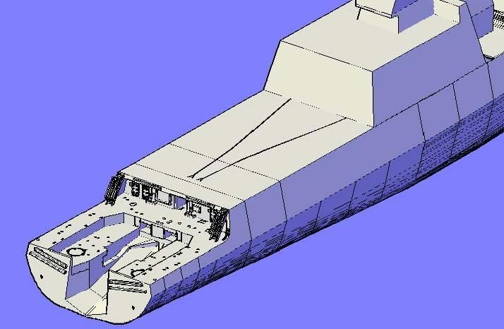
This morning, I thought I would do something quick and easy, so I started on the Helicopter Assist Track. Unfortunately, things didn�t turn out quite as planned. I have a good picture of the track�
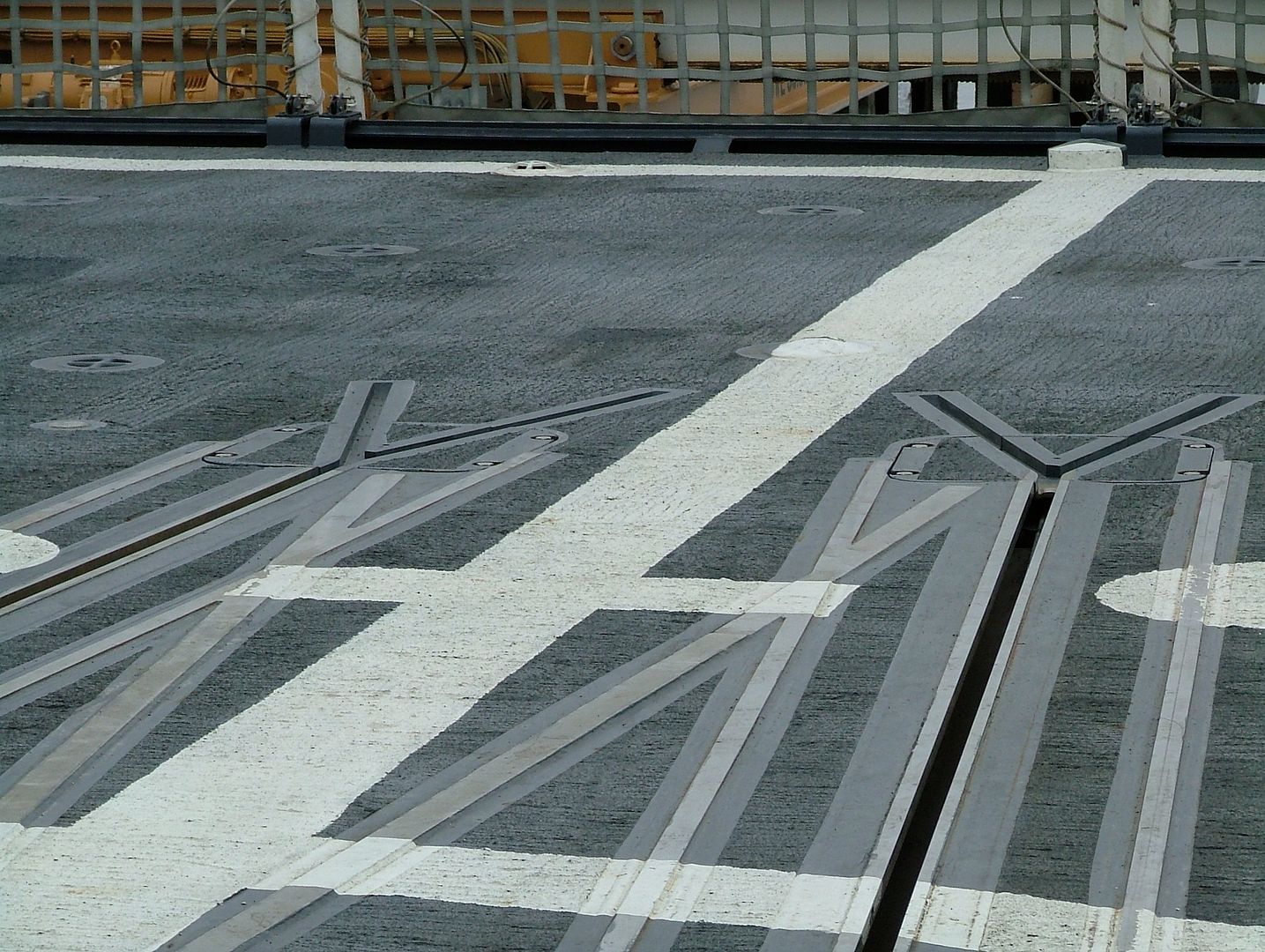
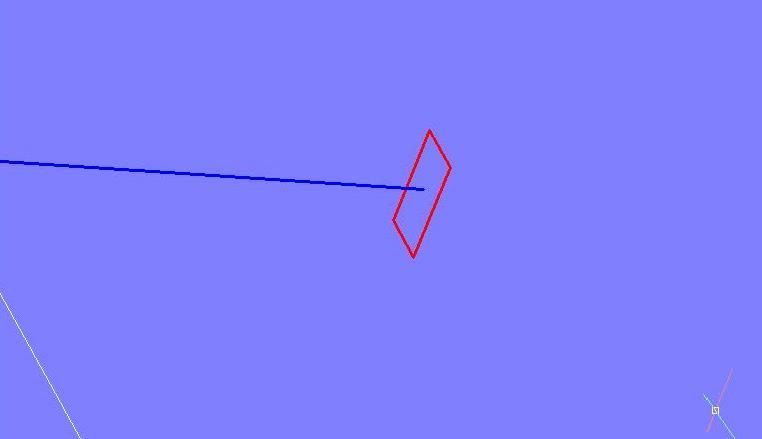
�And the �01 Level� plan sheet shows it too, so I stared by drawing a polyline of one of the tracks on the plan sheet. The splits at the aft end are just lines.
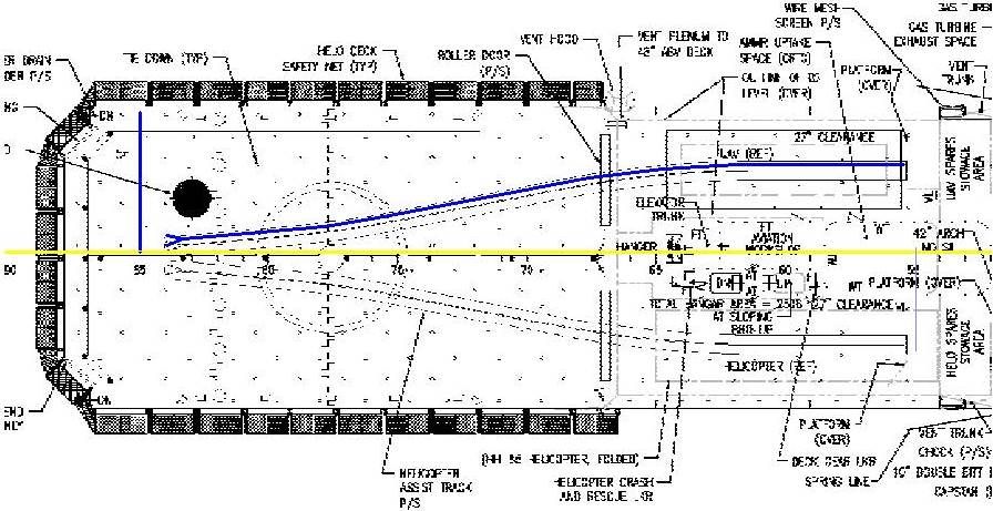
I then mirrored the polyline and lines to the other side�
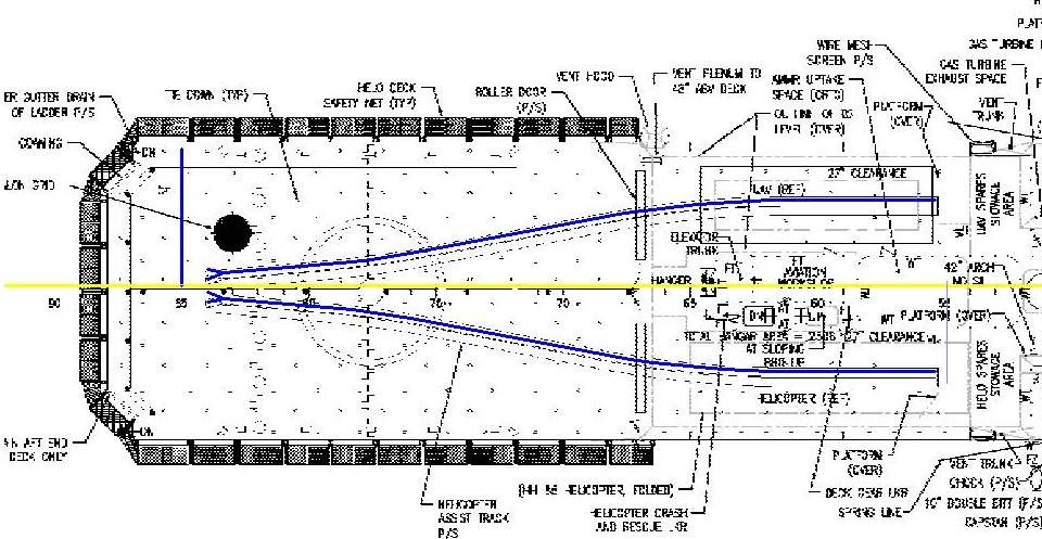
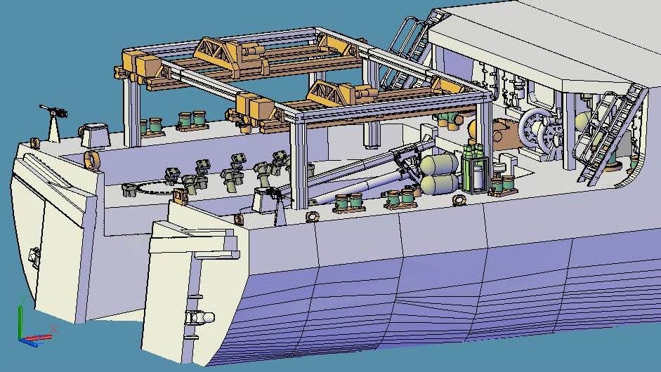
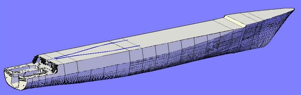
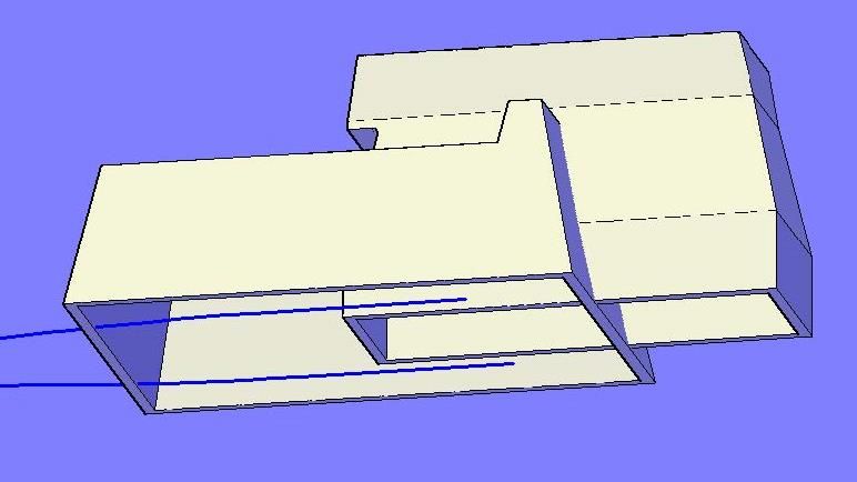
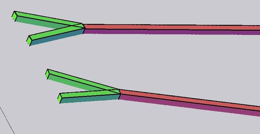
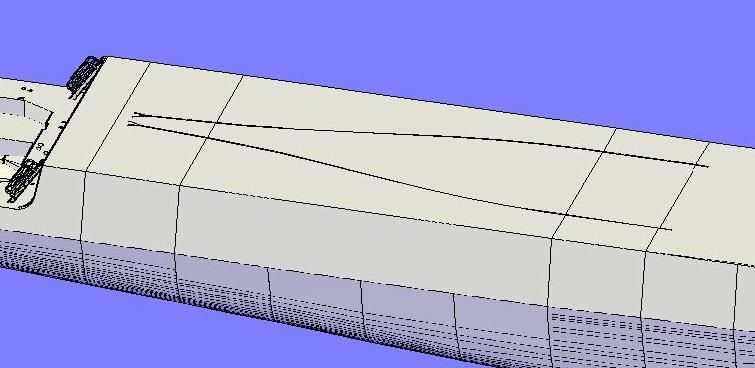
�And then copied them to the model. In this image you can see the tracks going into the hangar.
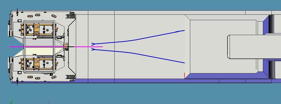
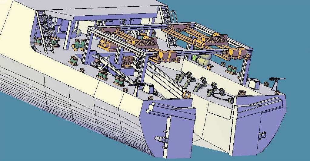
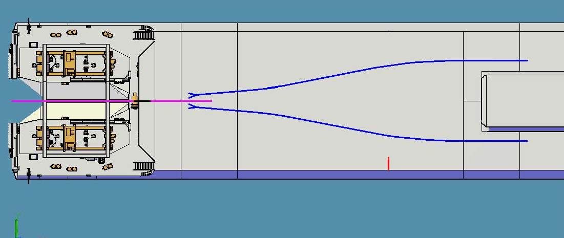
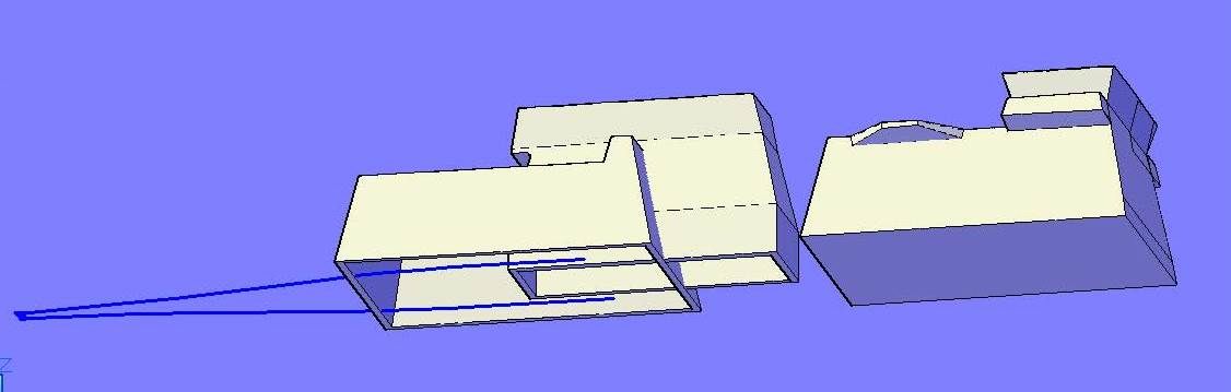
With the hangar layer turned off, you can see the all of the tracks.
?
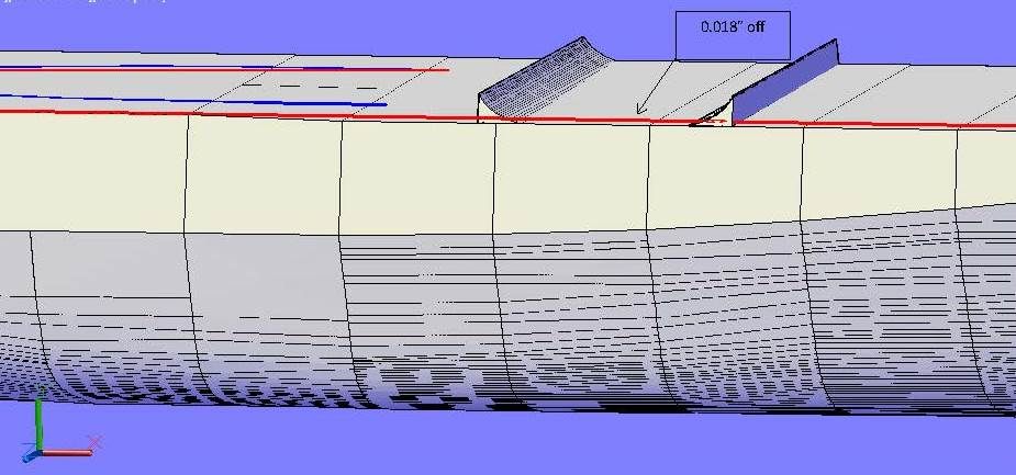
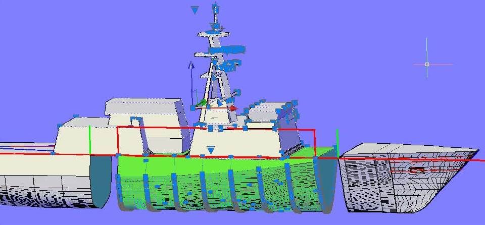
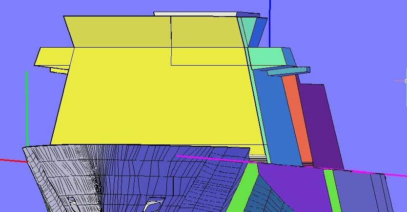
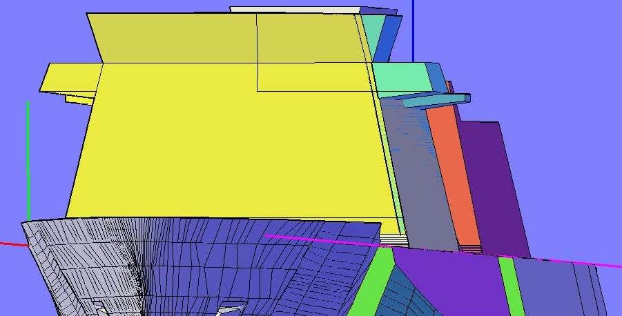
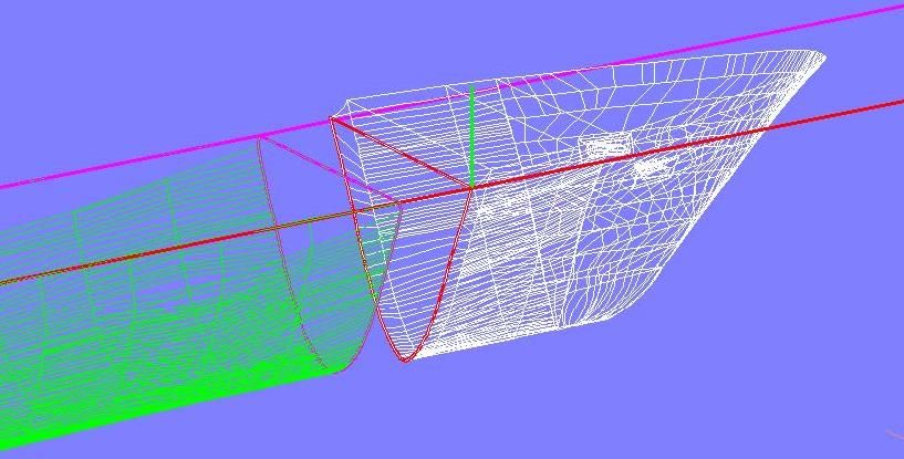
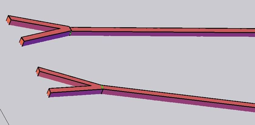
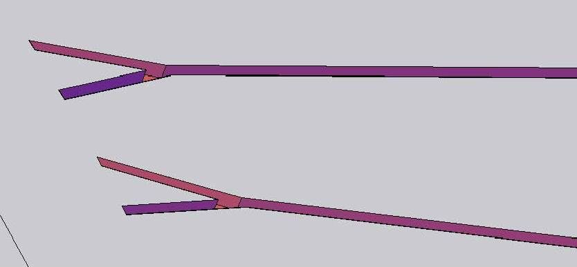
This is when my easy morning took an unexpected detour. Looking sideways I noticed that the deck wasn�t level. There was a 0.018� dip in the deck, as can be seen below. I have no idea how or when this happened. I�m blaming the CAD gremlins.
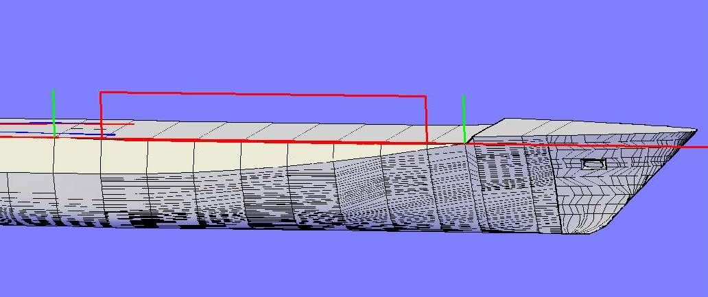
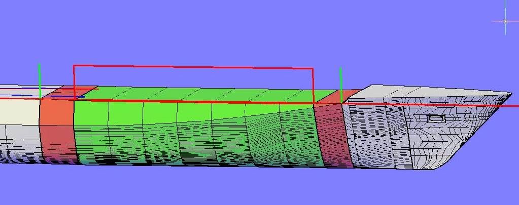
The image below shows where the deck is at the correct level (green) and where it dips (red).
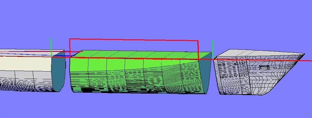
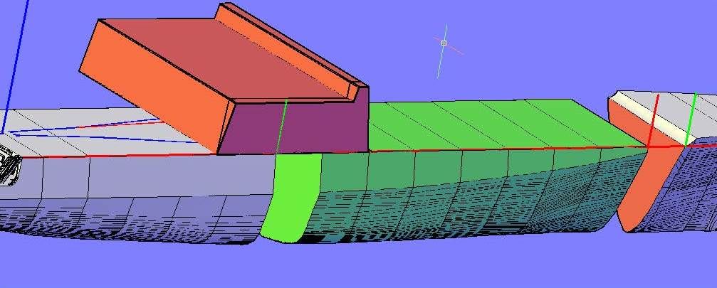
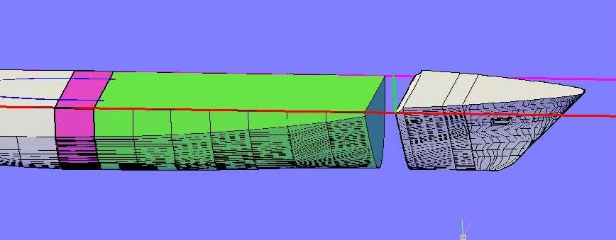
So, I sliced the hull into 4 pieces�
�And deleted the two uneven segments.
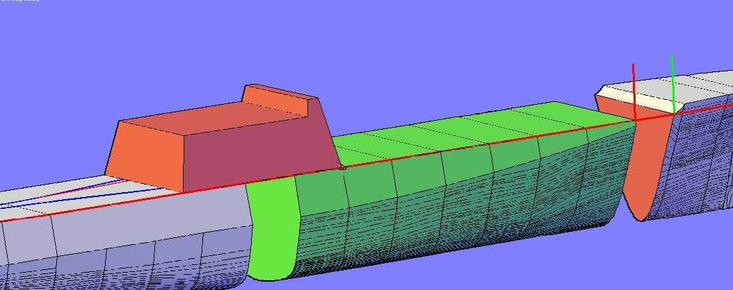
At this point I turned on the structure and mast layers and moved everything up 0.018�.
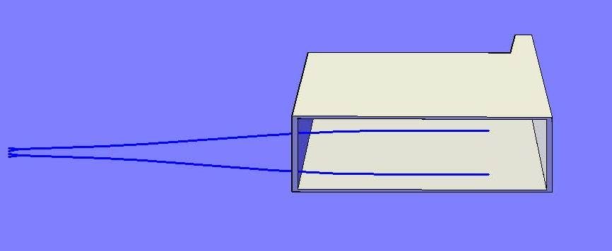
Unfortunately, the hangar part was out of whack, so I quickly redid it, using the profile outline to draw a polyline starting at the edge of the deck, extruding it past the deck�
�And sliced even with the sloped side of the hull.
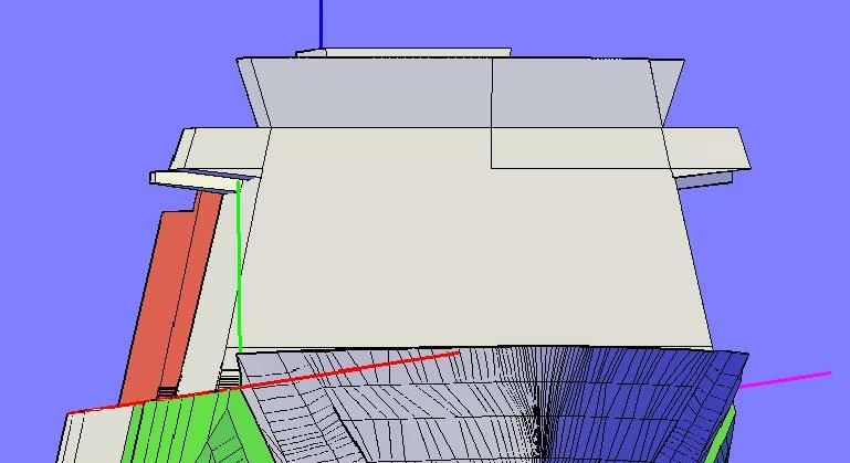
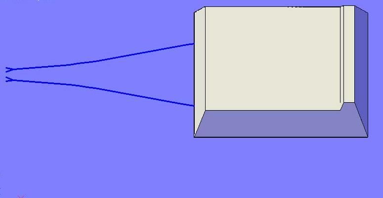
I then turned the Bridge/Pilot house structure layer on and you can see in the image below that it lined up nicely on the starboard side.
Not so on the port side, so I sliced it even with the sloped side of the hull�
�And moved it in.
With the structures right, I traced the effected hull sections, starting with the aft most two�
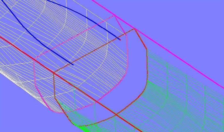
�And lofted them together.
I then did the same with the forward two sections�
�And joined all of the hull sections together.
?
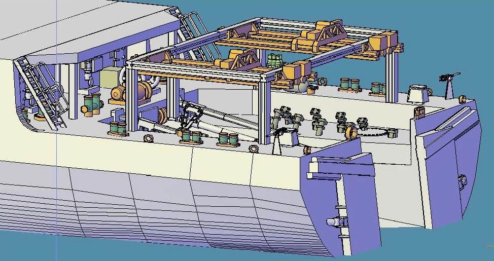
Now I was back where I started, with the track running into the hangar.
Since I hadn�t done it yet, and Pavel and I have agreed that the larger parts needed to be 3/64� (0.046�) thick, I decided to shell the parts before proceeding. I did the hangar structure part first�
�Followed by the stack structure part.
I tried to do the same for the bridge/pilot house structure part, but AutoCad couldn�t do it. That means I�m going to have to dice and slice it, or subtract features to get the correct thickness. I�m going to have to do the same with the hull sections I fear. Oh well, it is what it is, and I�ll deal with it later.
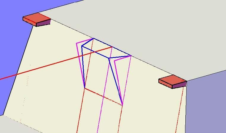
For now, it was back to the track, where I started by drawing a 0.010� square on the end of the track�
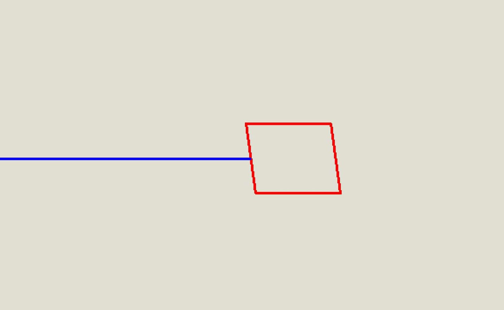
�And rotated it 90 degrees. (Note that I had to turn the hull layer off so it could be seen.)
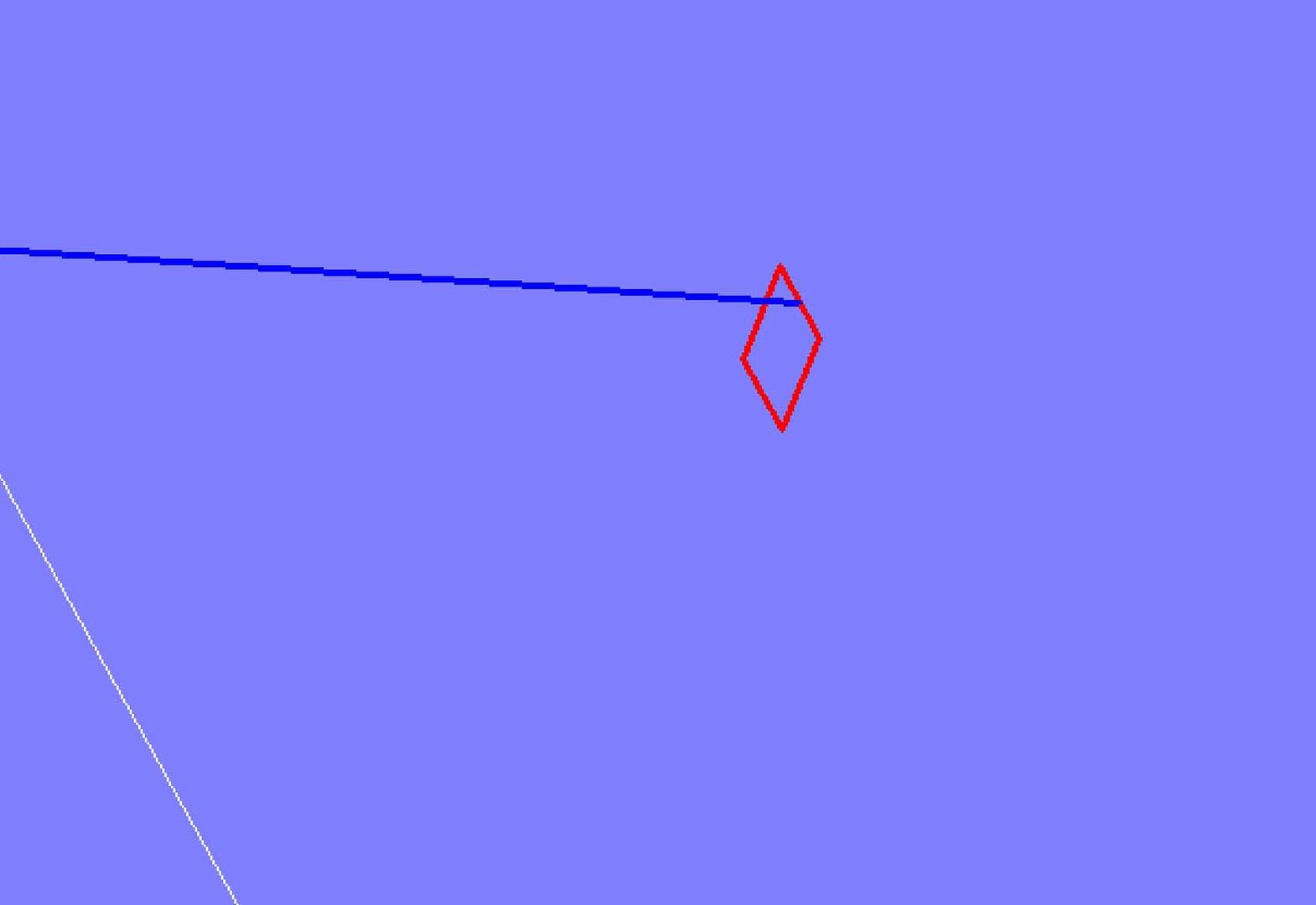
From experience I have learned that subtractions don�t always work like they should when two surfaces are at the same level, so I stretched the top of the rectangle up�
�Then I swept the rectangle along the polyline, and extruded it along the lines.
Then I joined the solids together�
�And subtracted them from the model.
I think the hangar doors are next.
CHEERS!!!


 [/URL]


