1/350 Goalkeeper close-in weapon system (CIWS) in AutoCad
Moderator: ArizonaBB39
-
Rdutnell

- Posts: 822
- Joined: Mon Dec 19, 2011 9:11 pm
- Location: Norman, Oklahoma
Re: 1/350 Goalkeeper close-in weapon system (CIWS) in AutoCa
Cool! Thanks Timmy!

Completed:
1/350 USS Missouri (BB-63) * 1/350 USS England (DE-635) * "Underway Personnel Transfer" Diorama
In Progress:
1/350 USS Bennington (CV-20)
1/144 USS Greenling (SSN-614) - ACAD/3D Printing
1/144 USS Batfish (SS-310) - ACAD/3D Printing
1/350 USS Missouri (BB-63) * 1/350 USS England (DE-635) * "Underway Personnel Transfer" Diorama
In Progress:
1/350 USS Bennington (CV-20)
1/144 USS Greenling (SSN-614) - ACAD/3D Printing
1/144 USS Batfish (SS-310) - ACAD/3D Printing
-
Rdutnell
- Posts: 822
- Joined: Mon Dec 19, 2011 9:11 pm
- Location: Norman, Oklahoma
Re: 1/350 Goalkeeper close-in weapon system (CIWS) in AutoCa
UPDATE 16
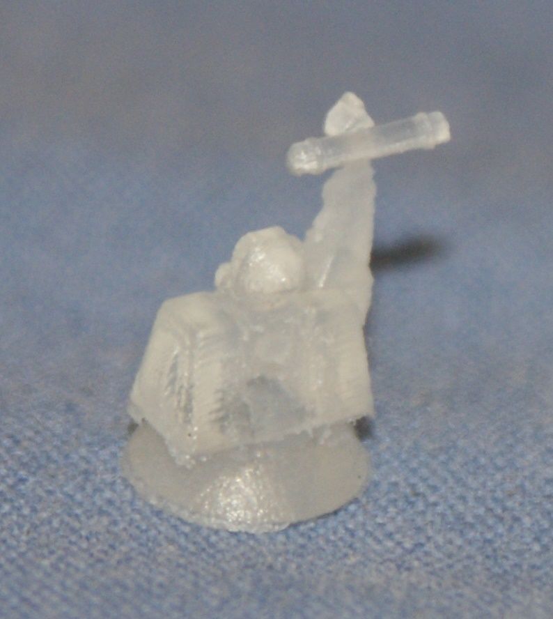
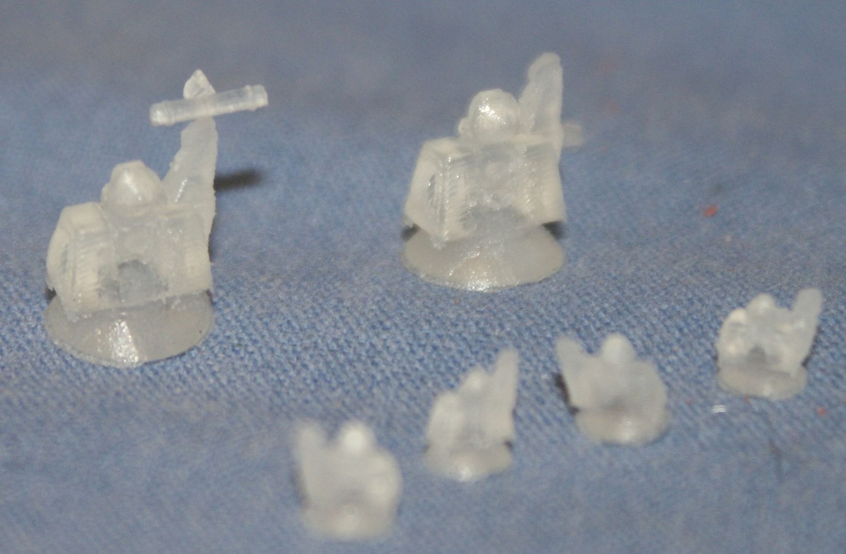
The first batch of printed parts arrived from Pavel yesterday and included the bow piece for my second Greenling model, and Goalkeepers and RAMs in both 1/350 scale and 1/700 scale. Here are a few pictures of the small pieces as they arrived. (Sorry that I didn�t put anything for scale but the weave is from a normal cotton sheet.)
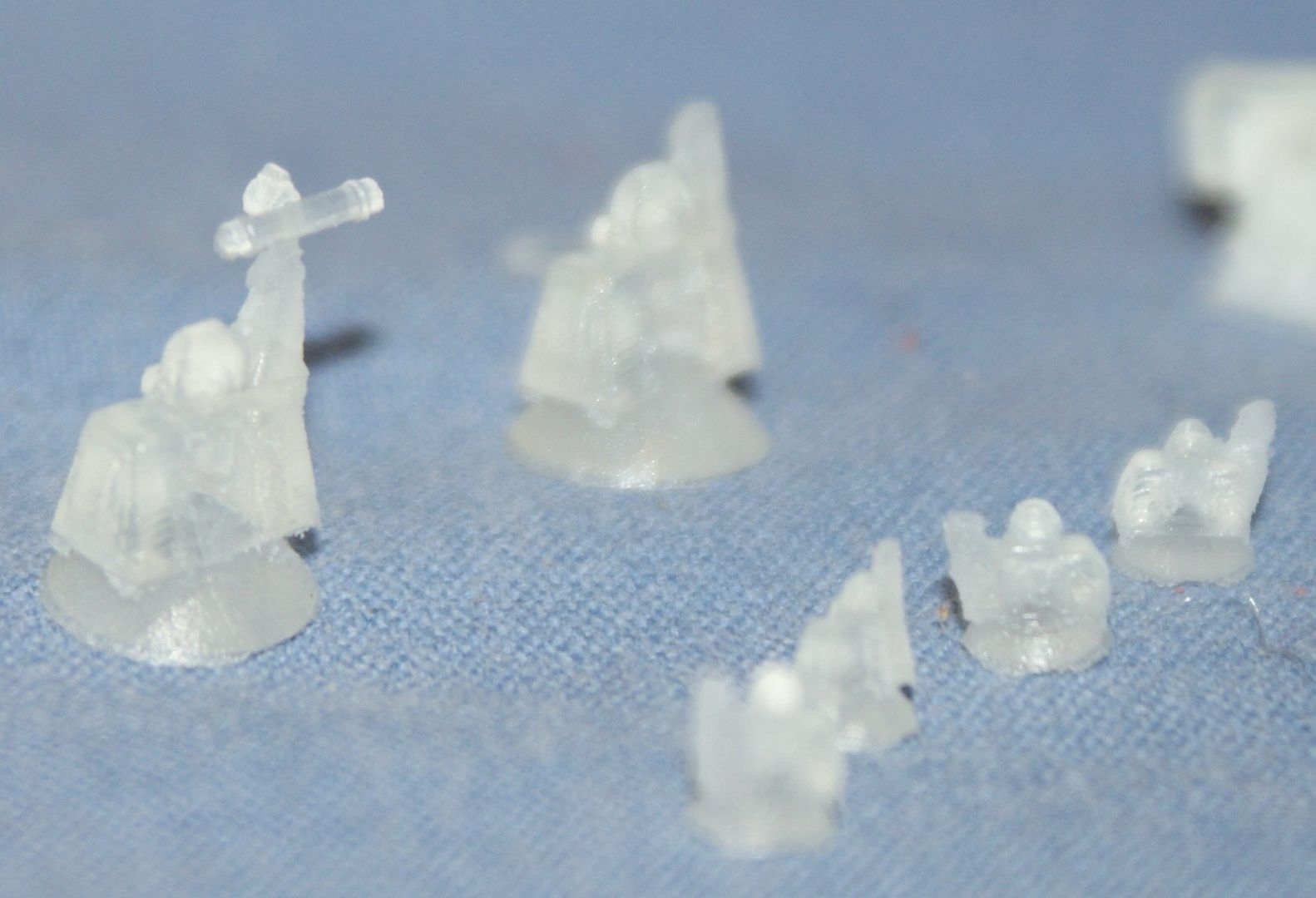
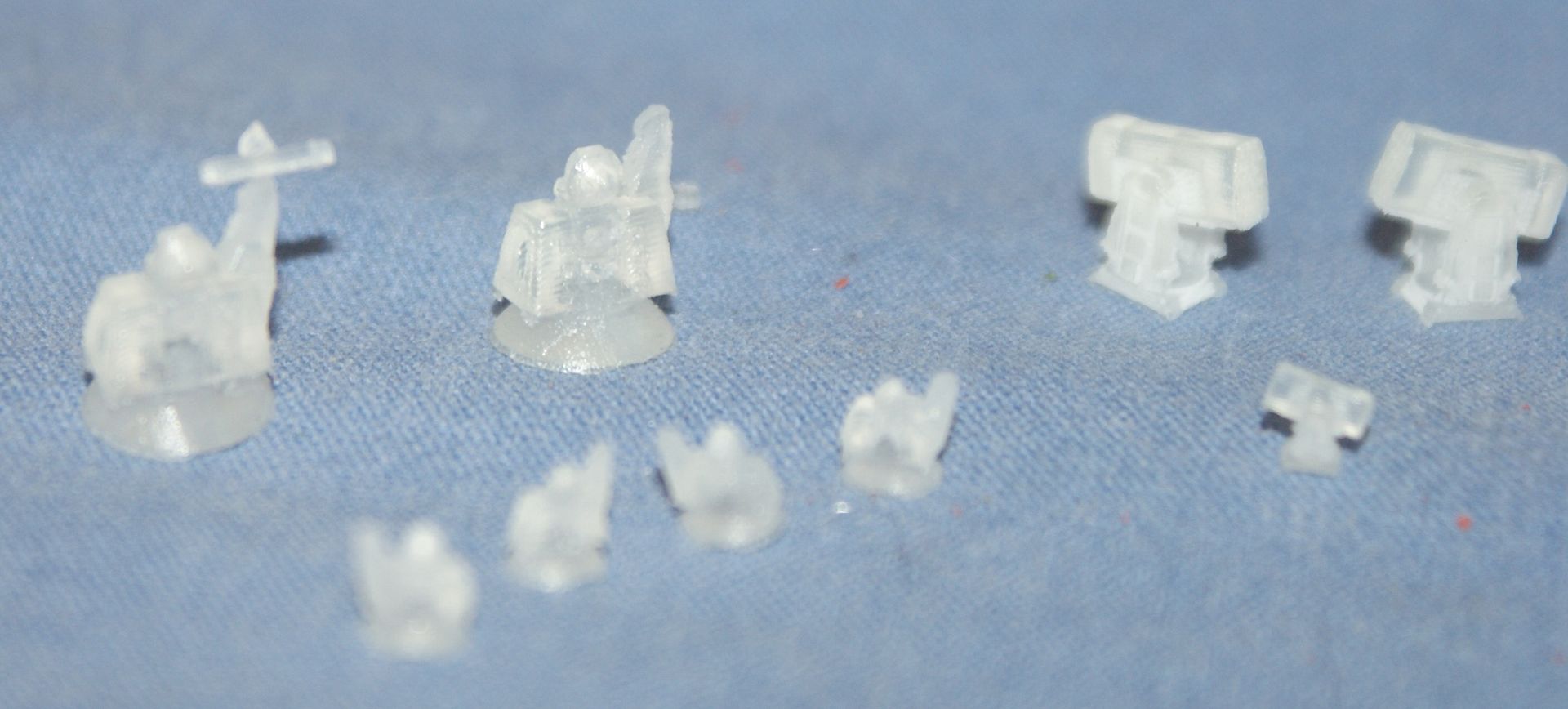
And here are a few pictures of them after I shot them with really bad primer. The dime really shows their small size.

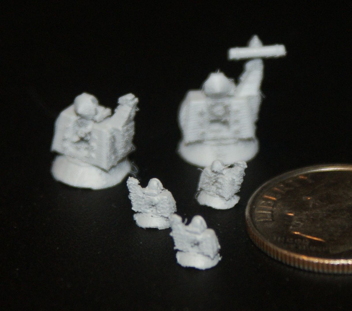
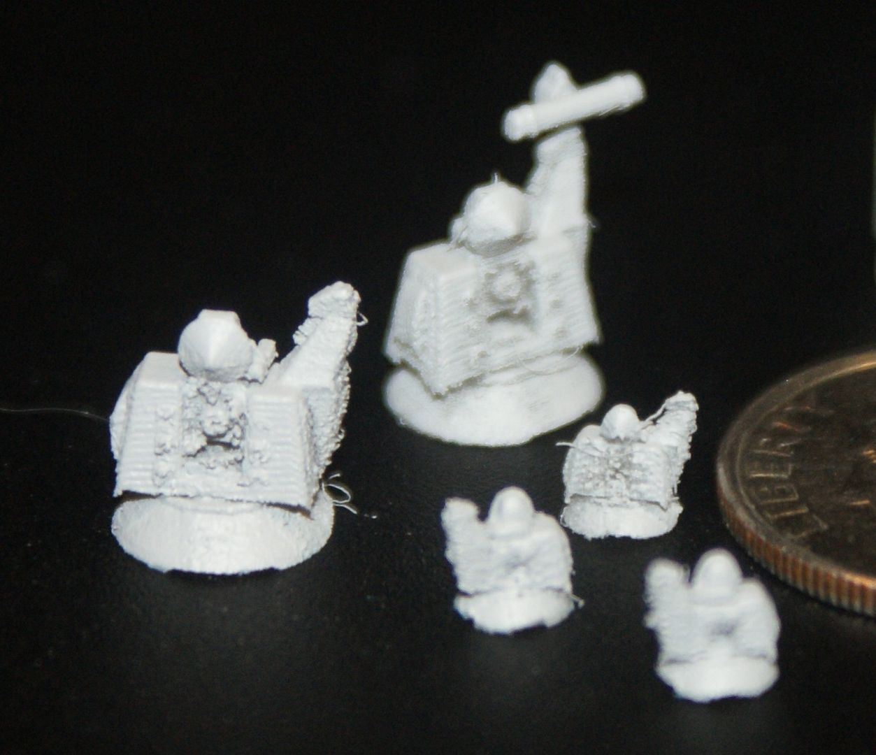
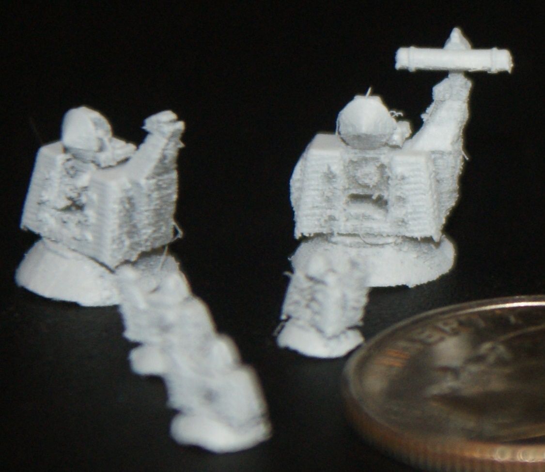
As you can see, the Goalkeepers are close, but they need work. The barrels didn�t even print at 1/700 scale and were so fragile at 1/350 scale that they didn�t make it to me intact. One of the 1/350 scale ones lost the antenna and all of the 1/700 scale antennas were knocked off in shipment.
I have already made alterations, beefing up everything I can, and have sent the files to Pavel for printing. I�ll keep you posted.
CHEERS!!!

The first batch of printed parts arrived from Pavel yesterday


And here are a few pictures of them after I shot them with really bad primer. The dime really shows their small size.


As you can see, the Goalkeepers are close, but they need work. The barrels didn�t even print at 1/700 scale and were so fragile at 1/350 scale that they didn�t make it to me intact. One of the 1/350 scale ones lost the antenna and all of the 1/700 scale antennas were knocked off in shipment.
I have already made alterations, beefing up everything I can, and have sent the files to Pavel for printing. I�ll keep you posted.
CHEERS!!!
Completed:
1/350 USS Missouri (BB-63) * 1/350 USS England (DE-635) * "Underway Personnel Transfer" Diorama
In Progress:
1/350 USS Bennington (CV-20)
1/144 USS Greenling (SSN-614) - ACAD/3D Printing
1/144 USS Batfish (SS-310) - ACAD/3D Printing
1/350 USS Missouri (BB-63) * 1/350 USS England (DE-635) * "Underway Personnel Transfer" Diorama
In Progress:
1/350 USS Bennington (CV-20)
1/144 USS Greenling (SSN-614) - ACAD/3D Printing
1/144 USS Batfish (SS-310) - ACAD/3D Printing
-
Brian Dale
- Posts: 53
- Joined: Sun Jul 09, 2006 12:12 pm
Re: 1/350 Goalkeeper close-in weapon system (CIWS) in AutoCa
The 1/700 ones are unuseable it seems? Did you remove all but the largest detail from them? I'm assuming that PAVEL used an objet printer? What resolution did they print them at? Have you tried to upload to a company that does SLA in really fine detail like fineline just for comparison?
-
Rdutnell
- Posts: 822
- Joined: Mon Dec 19, 2011 9:11 pm
- Location: Norman, Oklahoma
Re: 1/350 Goalkeeper close-in weapon system (CIWS) in AutoCa
This round sure was Brian, but I've redesigned them and we're trying again. The printer he has is a ProJet 3500HD Max, a very expensive Rapid Prototype machine that will do 16 micron layers. I don't know that it gets much better than that.
Completed:
1/350 USS Missouri (BB-63) * 1/350 USS England (DE-635) * "Underway Personnel Transfer" Diorama
In Progress:
1/350 USS Bennington (CV-20)
1/144 USS Greenling (SSN-614) - ACAD/3D Printing
1/144 USS Batfish (SS-310) - ACAD/3D Printing
1/350 USS Missouri (BB-63) * 1/350 USS England (DE-635) * "Underway Personnel Transfer" Diorama
In Progress:
1/350 USS Bennington (CV-20)
1/144 USS Greenling (SSN-614) - ACAD/3D Printing
1/144 USS Batfish (SS-310) - ACAD/3D Printing
-
desjeva
- Posts: 4
- Joined: Tue Sep 10, 2013 8:11 pm
Re: 1/350 Goalkeeper close-in weapon system (CIWS) in AutoCa
Looking good.
Ever consider doing a Kashtan system?
Ever consider doing a Kashtan system?
-
Ikje
- Posts: 2
- Joined: Mon Jan 27, 2014 5:47 am
Re: 1/350 Goalkeeper close-in weapon system (CIWS) in AutoCa
Any possibility for sharing the drawings?
I'm looking for drawings of a goalkeeper system to print a model for a colleague.
I'm looking for drawings of a goalkeeper system to print a model for a colleague.
-
Rdutnell
- Posts: 822
- Joined: Mon Dec 19, 2011 9:11 pm
- Location: Norman, Oklahoma
Re: 1/350 Goalkeeper close-in weapon system (CIWS) in AutoCa
Hi guys!
I haven't checked this site out in some time, so I apologize for the late response.
To answer your questions...
desjeva, I had not thought about doing a Kashtan system, and to be honest, I had never heard of them before I read your post.
Ikje, the Goalkeeper was made for Admiralty Model Works, who I understand intends to cast them, so unfortunately, I can't share the drawings. If I had done them for myself, I would be happy to share them. As it is though, I don't think I can. Sorry.
Completed:
1/350 USS Missouri (BB-63) * 1/350 USS England (DE-635) * "Underway Personnel Transfer" Diorama
In Progress:
1/350 USS Bennington (CV-20)
1/144 USS Greenling (SSN-614) - ACAD/3D Printing
1/144 USS Batfish (SS-310) - ACAD/3D Printing
1/350 USS Missouri (BB-63) * 1/350 USS England (DE-635) * "Underway Personnel Transfer" Diorama
In Progress:
1/350 USS Bennington (CV-20)
1/144 USS Greenling (SSN-614) - ACAD/3D Printing
1/144 USS Batfish (SS-310) - ACAD/3D Printing
-
Ikje
- Posts: 2
- Joined: Mon Jan 27, 2014 5:47 am
Re: 1/350 Goalkeeper close-in weapon system (CIWS) in AutoCa
Rdutnell,
Thanks for the reply.
To bad you're not able to share them but I can understand it.
Thanks for the reply.
To bad you're not able to share them but I can understand it.
-
Fritz

- Posts: 125
- Joined: Fri Aug 04, 2006 12:03 pm
- Location: Salem, MA, USA
Re: 1/350 Goalkeeper close-in weapon system (CIWS) in AutoCa
Rdutnell:
When designing for Print table style RP (versus 3 axis milling) I've discovered that despite the Micron resolution, there are still size resolution issues due to the software used to break the .stl files down to layers. There are also casting limitations for fine or thin walled structures.
Some go-bys that have worked well for me so far (many discovered by trial and error):
Minimum proud detail size: 10 thou high, and 10 thou wide (0.01"x0.01") Since masters get scaled up a little to account for resin shrinkage, this means you can get away with 3" x3" for 1/350 and 7"x7" for 1/700. For details smaller than this, like dogs on hatches, its best to go the route of adding photo-etch hatches on the master later.
Minimum scribe depth and width: Again 10 thou x 10 thou. This isn't a whole heck of a lot larger than if it was scribed by hand. When dealing with several scribed details close together, it may require adjusting the spacings between details or the overall size of the detail so as to still leave 10 thou between the scribed lines. For a more fine and scale spacing for, say, a planked deck, it would be best to do a photoetch deck to be added to the master (akin to what we had to do for the Nautilus).
Minimum blind hole size, or proud cylinder size: 14thou diameter x 10 thou deep/high
Minimum pipe trace/cable run diameter: 16 thou. While most cable runs are smaller than this , they may have to be added with microfine wire to the master afterward.
Whenever possible, orient these small details horizontal or vertical to the print plane. For example, if you have a small box on an inclined plane or bulkhead, make the upper or lower sides of the box horizontal for a steep incline, or vertical for a shallow incline. Compare the limber holes on the Gudgeon, with how I punched them on the Albacore and Growler. On Gudgeon punched the holes perfectly perpendicular to the superstructure side, with the result that the upper and lower edges came out soft on the print. Starting with Albacore I started punching them horizontally which tightens things up a bit.
For fine edges such as stems or trailing edges of a foil: Add a minimum 10 thou flat. It will print crisper, and prevent the edge from tearing when removed from the mold. Had this issue with the Worcester hull stem. I made it too fine and many hull casts wound up with chipped bow stems.
For thin walled structures: splinter shields and bulwarks should be minimum 12-13 thou at the base tapered to 10 thou at the top for 1/350 this allows for the appearance of fineness while allowing for releasing from the mold without tearing. For 1/700 you might be able to push this to 12 thou at the bottom to 9 thou at the top (but in all seriousness I haven't tried this yet). I tried to go to flat 8 thou on the bilge keels for the Gudgeon, but they turned out too fragile on the print and had to be stripped and replaced. The more taper you can add to the section, the stronger it will be.
For deep wells and recesses, such as cockpits on the tops of sails, minimum of 20 thou. This, again, is a casting consideration.
For slender items less such as stanchions or scopes: less than a 1/4" 16 thou dia, less than 1/2" 20 thou dia, less than 1" go for 35 thou, and taper a bit at the top if you have to.
For parts fit, such as tab and slot, or post in hole, allow for a minimum of 5 thou clearance on all sides to take into account differences in resin shrinkage.
Hope this helps
Best Regards
Fritz K.
Fritz K.