Calling all USS Lexington CV-2 fans
Moderators: BB62vet, MartinJQuinn, Timmy C, Gernot, Olaf Held, Dan K, HMAS, ModelMonkey
-
Dick J

- Posts: 1992
- Joined: Mon Aug 06, 2007 6:29 pm
Re: Calling all USS Lexington CV-2 fans
I am afraid I don't know how they were launched. I suspect that not much of a procedure was specified because the method would probably vary with the circumstances - "How much time do I have to get the thing in the water?" Obviously, when Lexington went down, the crew had a bit more time for an organized launch. As for Yorktown, while her abandonment was organized, it was a bit more hurried than that of Lexington. The raft launch was probably expedited.
-
marijn van gils
- Posts: 2736
- Joined: Tue Feb 06, 2007 10:24 am
- Location: Belgium
Re: Calling all USS Lexington CV-2 fans
Ok, thanks!
-
marijn van gils
- Posts: 2736
- Joined: Tue Feb 06, 2007 10:24 am
- Location: Belgium
Re: Calling all USS Lexington CV-2 fans
Another question:
In the picture below, from the Steve Wiper book, there are a couple of items that are not clear to me:
1) The "FC radar antenna": which might this be? And how does that look like (any close-up pics from other ships?)?
2) Near the bottom of the main mast, there is something attached to the front of it. What could this be, and how does it look like close-up?
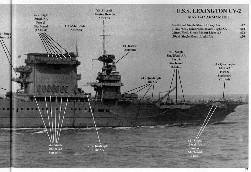
Many thanks,
Marijn
In the picture below, from the Steve Wiper book, there are a couple of items that are not clear to me:
1) The "FC radar antenna": which might this be? And how does that look like (any close-up pics from other ships?)?
2) Near the bottom of the main mast, there is something attached to the front of it. What could this be, and how does it look like close-up?
Many thanks,
Marijn
-
lvsquarerigger
- Posts: 398
- Joined: Tue Feb 17, 2009 12:26 am
- Location: Albuquerque, NM
Re: Calling all USS Lexington CV-2 fans
Haven't posted anything on my own build lately as I have had other things to deal with but if you go to:
viewtopic.php?f=59&t=40911&start=220
You'll see how I dealt with that part, although in 1/350, and there are a lot of pics for you to refer to also.
Good luck with your build,
James
viewtopic.php?f=59&t=40911&start=220
You'll see how I dealt with that part, although in 1/350, and there are a lot of pics for you to refer to also.
Good luck with your build,
James
-
Dick J
- Posts: 1992
- Joined: Mon Aug 06, 2007 6:29 pm
Re: Calling all USS Lexington CV-2 fans
Earlier in this thread, check the photos at the bottom of this page:marijn van gils wrote:1) The "FC radar antenna": which might this be? And how does that look like (any close-up pics from other ships?)?
viewtopic.php?f=46&t=7216&start=520
This particular antenna is the same one as on the MK-34 director of the Helena (the upper director) in this photo at Navsource:
http://www.navsource.org/archives/04/050/0405006.jpg
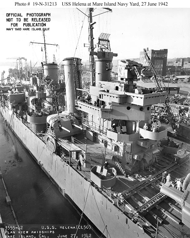
There were two designs for the FC antenna (also known as the MK-3 fire control radar). This one was almost square when viewed from head on. Lexington and Helena had this type. The other is the horizontal rectangular antenna seen in early war photos of the pre-war battleships and many of the cruisers.
The front of this rectangular antenna can be seen here on Pennsylvania:
http://navsource.org/archives/01/038/013874a.jpg
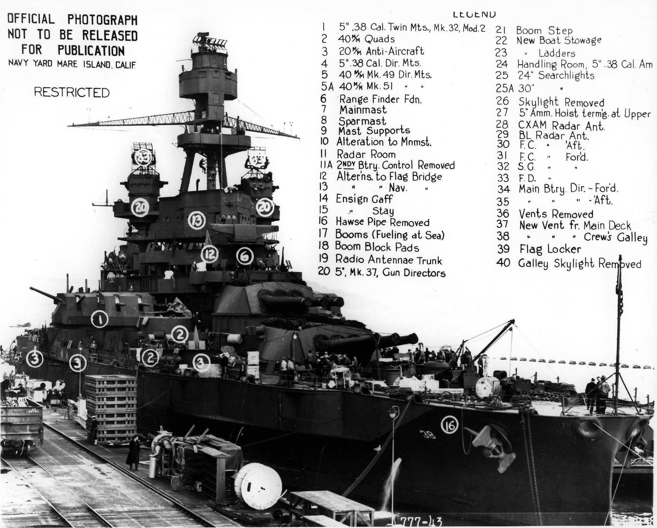
And the back side of it can be seen here on Maryland:
http://navsource.org/archives/01/036/013630f.jpg
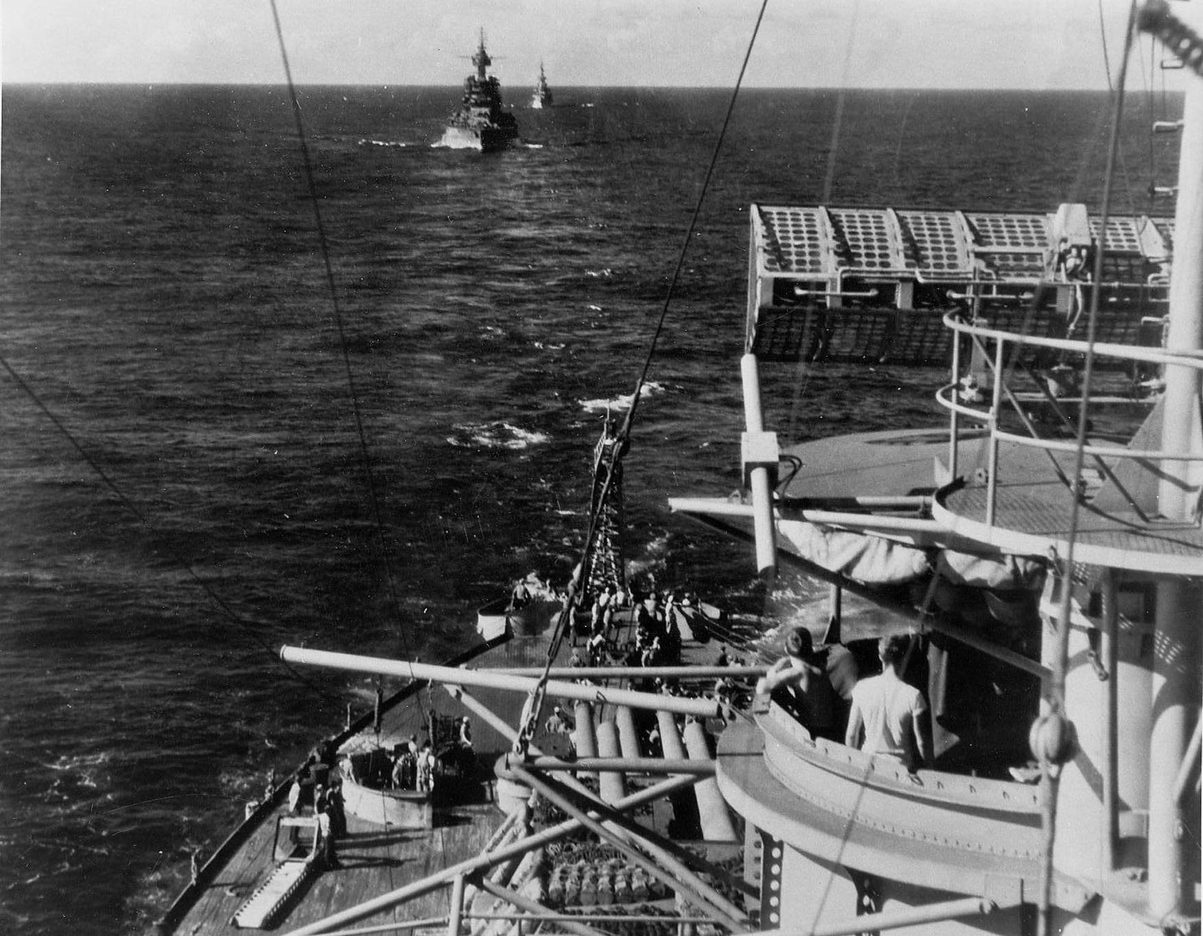
But Lexington had the same version seen in the Helena photo.
-
marijn van gils
- Posts: 2736
- Joined: Tue Feb 06, 2007 10:24 am
- Location: Belgium
Re: Calling all USS Lexington CV-2 fans
Many thanks! That solves the radar mystery for me!
lvsquarerigger: very nice build! Thanks for the link, I will be following it.
Any idea what the "thing" at the bottom of the main mast, just above the control top platform?
It is most visible in the photo on the bottom of this page: viewtopic.php?f=46&t=7216&start=520
Thanks,
Marijn
lvsquarerigger: very nice build! Thanks for the link, I will be following it.
Any idea what the "thing" at the bottom of the main mast, just above the control top platform?
It is most visible in the photo on the bottom of this page: viewtopic.php?f=46&t=7216&start=520
Thanks,
Marijn
-
Jon C Ryckert

- Posts: 586
- Joined: Sat Jun 06, 2009 12:40 pm
Re: Calling all USS Lexington CV-2 fans
Maybe it is a 'crow's nest' like what you would see on the Titanic.
-
marijn van gils
- Posts: 2736
- Joined: Tue Feb 06, 2007 10:24 am
- Location: Belgium
Re: Calling all USS Lexington CV-2 fans
Thanks Jon!
That was my first idea too, but it just seems to make little sense to have a crows nest only one or two meters above the control top platform.
But unless anyone has a better idea, that's what I will go with anyway. Life is too short to leave models unfinished because of lack of historical inormation!
Marijn
That was my first idea too, but it just seems to make little sense to have a crows nest only one or two meters above the control top platform.
But unless anyone has a better idea, that's what I will go with anyway. Life is too short to leave models unfinished because of lack of historical inormation!
Marijn
-
Michael Vorrasi
- Posts: 476
- Joined: Sun May 08, 2005 11:15 am
- Location: Brooklyn NY USA
Re: Calling all USS Lexington CV-2 fans
An enclosure to house some of the radar or other electronic equipment makes a bit more sense than a crow's nest. Just a SWAG* on my part.marijn van gils wrote:Thanks Jon!
That was my first idea too, but it just seems to make little sense to have a crows nest only one or two meters above the control top platform.
But unless anyone has a better idea, that's what I will go with anyway. Life is too short to leave models unfinished because of lack of historical inormation!
Marijn
*Scientific Wild Ass Guess
Mike

-
marijn van gils
- Posts: 2736
- Joined: Tue Feb 06, 2007 10:24 am
- Location: Belgium
Re: Calling all USS Lexington CV-2 fans
Thanks Mike!
Guessing is all we can do...
In the end, I just modelled the shape as I see it in the pics, as you see in the build tread I just started: viewtopic.php?f=59&t=155672
Guessing is all we can do...
In the end, I just modelled the shape as I see it in the pics, as you see in the build tread I just started: viewtopic.php?f=59&t=155672
-
Geno the Viking
- Posts: 79
- Joined: Sat Dec 10, 2011 6:36 pm
- Location: Everett, Washington
Re: Calling all USS Lexington CV-2 fans
This may have been covered before but does anyone know for sure what camouflage Lexington had at Coral Sea? I've found conflicting information that she was painted in MS11 at Pearl Harbor, but other sources say MS 21. At least we know she was blue.
-
Dick J
- Posts: 1992
- Joined: Mon Aug 06, 2007 6:29 pm
Re: Calling all USS Lexington CV-2 fans
In a way, both are correct. At the time of her loss, MS-21 (overall Navy Blue) did not yet officially exist. MS-11 called for "Sea Blue", but the Pacific Fleet decided that was too light and substituted "Navy Blue" for the Sea Blue. This darker paint scheme was later codified as MS-21. The photos of Lexington appear to be dark enough to be Navy Blue, and the Pacific Fleet was no longer using Sea Blue, so it is highly likely that she was overall Navy Blue, even though she was officially in MS-11.
-
abledog1
- Posts: 2
- Joined: Sat Jul 24, 2010 10:44 am
 Windbreaks ("palisades") colors
Both Lex and Sara had folding windbreaks called "palisades" which were raised to block wind across the flight deck. What color were they on the pre-war mahogany-stained flight decks?
-
dbiggied
- Posts: 37
- Joined: Sat Jan 26, 2013 1:30 pm
Re: Calling all USS Lexington CV-2 fans
I've been working on the hull of my Lex...build log is coming...but for now I'm hoping for some input. I've noticed some discrepancies between the HNSA plans, the books, and the kit that I don't recall anyone specifically addressing.
#1. As shown below, on the HNSA plans some of the pockets are NOT symmetrical. (non-vertical edges, different curves, sloping tops, etc) HOWEVER, in every book I have, every picture I've examined looks like the pockets ARE all even and symmetrical both horizontal and vertical (Squadron book pgs 28 and 36). I'm inclined to trust photo evidence over the plans. Opinions?

#2. The picture below is from a 1/350 scale copy of the HNSA plans. The scale of the plans has been verified by measurement of fore and aft perpendiculars and length overall of flight deck, and also by laying the kit deck on the plans. The red line is a tracing of the 3 parts of the kit island base (E1, E2, E18). As you can see, the base of the HNSA island is noticeably narrower than the kit parts, and comes to a sharper edge at the back. I've seen plenty of discussion of accurizing the platforms and upper levels of the island, but I don't remember if anyone narrowed or reshaped the base. On this I'd be inclined to trust the plans over the kit. Opinions?

#1. As shown below, on the HNSA plans some of the pockets are NOT symmetrical. (non-vertical edges, different curves, sloping tops, etc) HOWEVER, in every book I have, every picture I've examined looks like the pockets ARE all even and symmetrical both horizontal and vertical (Squadron book pgs 28 and 36). I'm inclined to trust photo evidence over the plans. Opinions?
#2. The picture below is from a 1/350 scale copy of the HNSA plans. The scale of the plans has been verified by measurement of fore and aft perpendiculars and length overall of flight deck, and also by laying the kit deck on the plans. The red line is a tracing of the 3 parts of the kit island base (E1, E2, E18). As you can see, the base of the HNSA island is noticeably narrower than the kit parts, and comes to a sharper edge at the back. I've seen plenty of discussion of accurizing the platforms and upper levels of the island, but I don't remember if anyone narrowed or reshaped the base. On this I'd be inclined to trust the plans over the kit. Opinions?
Doug W.
North Carolina
North Carolina
-
Geno the Viking
- Posts: 79
- Joined: Sat Dec 10, 2011 6:36 pm
- Location: Everett, Washington
Re: Calling all USS Lexington CV-2 fans
I would certainly always trust the photos if one has good ones. Good clear photos are essential for perfection.
I would trust plans over a kit.
Remember though that these plans you have are not working plans. They are just overall layouts. They have no dimensions and were never used during the ship construction. A good drafter would make these as accurate as possible and you have pointed out some very interesting features that may or may not be accurately represented. These are ships, so very little is square with the world. Even builders plans were modified and in some cases not built correctly.
I love your observations as I taught drafting and design for thirty years.
Don't get an ulcer just do your best with in info you have.
I would trust plans over a kit.
Remember though that these plans you have are not working plans. They are just overall layouts. They have no dimensions and were never used during the ship construction. A good drafter would make these as accurate as possible and you have pointed out some very interesting features that may or may not be accurately represented. These are ships, so very little is square with the world. Even builders plans were modified and in some cases not built correctly.
I love your observations as I taught drafting and design for thirty years.
Don't get an ulcer just do your best with in info you have.
-
lvsquarerigger
- Posts: 398
- Joined: Tue Feb 17, 2009 12:26 am
- Location: Albuquerque, NM
Re: Calling all USS Lexington CV-2 fans
Funny I never noticed that particular facet of the bridge. Although there is a slight discrepancy between where it sits in the kit and where it is on the plans it's so small I didn't think it was worth bothering with. The shape now that's entirely different. Maybe that explains why I had so much trouble getting the mast posts to line up. I did rebuild the lower forward section to the square layout, not the cut off way the kit is, and also modified the rounded conning section as the kit part is too big, too round, and too far forward. Now I guess I'll have to go back and scratch it all. I can just cut off the lower section as it's all scratch built from the nav deck up. Nice catch.dbiggied wrote:I've been working on the hull of my Lex...build log is coming...but for now I'm hoping for some input. I've noticed some discrepancies between the HNSA plans, the books, and the kit that I don't recall anyone specifically addressing.
#
#2. The picture below is from a 1/350 scale copy of the HNSA plans. The scale of the plans has been verified by measurement of fore and aft perpendiculars and length overall of flight deck, and also by laying the kit deck on the plans. The red line is a tracing of the 3 parts of the kit island base (E1, E2, E18). As you can see, the base of the HNSA island is noticeably narrower than the kit parts, and comes to a sharper edge at the back. I've seen plenty of discussion of accurizing the platforms and upper levels of the island, but I don't remember if anyone narrowed or reshaped the base. On this I'd be inclined to trust the plans over the kit. Opinions?
As for the pockets I copied the plans, set them on some thin styrene, and cut them out and then fitted them to the hull. I hadn't really noted the different angles of the vertical portions of the cutout but will definitely check. As for me I've always gone with pics over plans.
James
-
Dick J
- Posts: 1992
- Joined: Mon Aug 06, 2007 6:29 pm
Re: Calling all USS Lexington CV-2 fans
That angled facet on the front of the structure was probably due to a misinterpretation of someone else's drawing at some point. The actual structure was squared off. However, when the 8" turrets were in place, they were the same width as the structure. So to gain access to the hatches, which were on the sides of the turrets, "catwalks" extended the width of the deck only. On the inboard side, they had rounded corners. However, the forward edge of the outboard catwalk was angled from the corner where it joined the lower structure back at about a 45 degree angle. The after corner was rounded like the corners on the inboard side. The angled area did not extend to the bulkheads holding up the deck. The reason for the angled edge was the fact that turret I was slightly more inboard than the rest of the structure and the angle gave the turret a couple more degrees in the starboard after arc of fire. Another thing that is totally misinterpreted is Lexington's later 1.1' gun bulwarks. They were directly above the bulkheads below them, not placed at the outboard edges of the catwalk extensions to the deck. Trumpy got that one totally wrong.
-
lvsquarerigger
- Posts: 398
- Joined: Tue Feb 17, 2009 12:26 am
- Location: Albuquerque, NM
Re: Calling all USS Lexington CV-2 fans
Ok. Had time this morning and compared my bridge to the HNSA plans I have. A word about the plans; being photoshop challenged, both in the program and capabilities, I went a different way. A 1/350 set would be 54.85% of the 1/196 plans as they come so I downloaded them to a flash drive and went off to FedEx office. Had them resize the plans, printed out the flight deck, compared that to the actual kit and found they matched. Then printed out the plans I felt I needed and use those for my modeling. It's so nice to be able to compare parts to the actual dimensions. Just a quick check with the digital calipers and you're on your way. Having said that I drug them out, along with my rebuilt bridge, and found for the most part the kit matches the plans. Width and length match. What does seem to be different is the way the plans come to a point and the kit does not. The kit is more rounded. Now the question is what do I do about it? Haven't decided yet but this is just more info for us anally challenged people out there to work with. Whatever you choose is the right thing for you. The important thing is to have fun doing it. If you lose that why bother?
James
James
-
dbiggied
- Posts: 37
- Joined: Sat Jan 26, 2013 1:30 pm
Re: Calling all USS Lexington CV-2 fans
My reduction percentage in Photoshop was almost exactly the same as yours at the copy shop. I also verified the width of the flight deck on the plans by laying my kit deck on a printout. so my plans should be the right size...but my kit island base is still noticeably wider than the plans. I have to wonder if Trumpeter made changes mid-production...one more thing to worry about, right? 
Anyway, I might have found confirmation of the shape of the back end. The following picture comes from the Squadron book page 23 of the Lexington under construction. The line bracketed by the arrows looks like the back edge of the lower island structure, and it looks like it comes to a fairly sharp edge. Still no confirmation of the width question. Most likely I will keep the kit width, but correct the shape of the back edge, and move the island outwards.

Anyway, I might have found confirmation of the shape of the back end. The following picture comes from the Squadron book page 23 of the Lexington under construction. The line bracketed by the arrows looks like the back edge of the lower island structure, and it looks like it comes to a fairly sharp edge. Still no confirmation of the width question. Most likely I will keep the kit width, but correct the shape of the back edge, and move the island outwards.
Doug W.
North Carolina
North Carolina
-
lvsquarerigger
- Posts: 398
- Joined: Tue Feb 17, 2009 12:26 am
- Location: Albuquerque, NM
Re: Calling all USS Lexington CV-2 fans
I saw that this morning and also on pg 40 is the clearest shot of the whole back I could find but figured I might be over posting. Aaaahhhh what the h---
James
James