Francis,
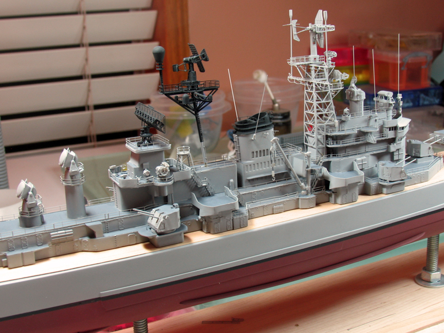
The model in your picture isn't very accurate for the missile tracking radars. It looks like the base and yoke are a single piece.
See this location for a description of how the tracking antenna parts worked for the AN/SPG-49 missile tracking radar used with Talos. The Terrier missile tracking radars used the same mechanical parts for rotation about bearing and elevation - both systems were in development at the same time and the Navy didn't know that either would work, so they designed as many parts as possible to be the same in both systems.
http://www.okieboat.com/SPG-49%20description.html
Note: The electronics were totally different for Talos and Terrier, and the guts of the Terrier tracking radars were entirely different from the AN/SPG-49.
Phil
Calling all USS Boston CAG-1 fans!
Moderators: MartinJQuinn, Timmy C, Gernot, Olaf Held, Dan K, HMAS, ModelMonkey
-
DrPR

- Posts: 1689
- Joined: Sun Mar 07, 2010 12:01 am
- Location: Corvallis, Oregon, USA
- Contact:
Re: Calling all CAG-1 USS Boston Fans!
A collision at sea will ruin your entire day. Aristotle
-
CAG-1NUT
- Posts: 112
- Joined: Fri Jan 16, 2015 3:12 pm
- Location: Spotsylvania, Va. U.S.A.
how wide are the planks on the these ships?
Like topic asks. I'm about to order some and want to get the right plank spacing for the USS Boston. the scale is 1/8"= 1'
Does anyone know a another supplier for model ship deck besides Northeastern?
Thanks
Francis
Does anyone know a another supplier for model ship deck besides Northeastern?
Thanks
Francis
Build em big
-
Timmy C

- Posts: 12454
- Joined: Mon Jan 10, 2005 6:00 pm
- Location: Ottawa, Canada
Re: Calling all CAG-1 USS Boston Fans!
Francis: when posting a question or response about a ship that already has a topic thread, please use the "New Reply" button while viewing the existing thread and not the "New Topic". This helps to keep the board more organized. Thanks!
De quoi s'agit-il?
-
DrPR
- Posts: 1689
- Joined: Sun Mar 07, 2010 12:01 am
- Location: Corvallis, Oregon, USA
- Contact:
Re: Calling all CAG-1 USS Boston Fans!
Francis,
I am curious. What were the dimensions of the planking on the CAGs?
On the CLGs the planks were 4"x2" and no shorter than 18 feet (of course in places they were cut shorter to fit). They were laminated with 1" teak over 1" Douglas fir, with the teak on top.
The caulked gap between planks was 3/16" wide.
The margin planks were 2.5"x9" and trimmed to 2" where they joined the deck planking. The 2.5" side fit against bulkheads, hatch coamings, etc. so water would flow away from the joint with the metal. Margin planks were not to be cut less than 6" wide.
Phil
A collision at sea will ruin your entire day. Aristotle
-
CAG-1NUT
- Posts: 112
- Joined: Fri Jan 16, 2015 3:12 pm
- Location: Spotsylvania, Va. U.S.A.
Re: Calling all CAG-1 USS Boston Fans!
Thanks, I feel ok with using decking sheets with 1/16" scoring, whereas the ship i'm building is a 1/96 and thus 1/16 = 6".DrPR wrote:Francis,
I am curious. What were the dimensions of the planking on the CAGs?
On the CLGs the planks were 4"x2" and no shorter than 18 feet (of course in places they were cut shorter to fit). They were laminated with 1" teak over 1" Douglas fir, with the teak on top.
The caulked gap between planks was 3/16" wide.
The margin planks were 2.5"x9" and trimmed to 2" where they joined the deck planking. The 2.5" side fit against bulkheads, hatch coamings, etc. so water would flow away from the joint with the metal. Margin planks were not to be cut less than 6" wide.
Phil
Build em big
-
CAG-1NUT
- Posts: 112
- Joined: Fri Jan 16, 2015 3:12 pm
- Location: Spotsylvania, Va. U.S.A.
Re: Calling all CAG-1 USS Boston Fans!
THANKS GREAT INFO!DrPR wrote:Francis,
The model in your picture isn't very accurate for the missile tracking radars. It looks like the base and yoke are a single piece.
See this location for a description of how the tracking antenna parts worked for the AN/SPG-49 missile tracking radar used with Talos. The Terrier missile tracking radars used the same mechanical parts for rotation about bearing and elevation - both systems were in development at the same time and the Navy didn't know that either would work, so they designed as many parts as possible to be the same in both systems.
http://www.okieboat.com/SPG-49%20description.html
Note: The electronics were totally different for Talos and Terrier, and the guts of the Terrier tracking radars were entirely different from the AN/SPG-49.
Phil
Aside from the SPGs train with the launchers, did scan up/down or left/right?
Build em big
-
Guest
Re: Calling all CAG-1 USS Boston Fans!
The SPG-49s did rotate around the horizontal axis to adjust the elevation. They also had the ability to oscillate back and forth around the vertical axis. The Talos tracking antennas operated independently in bearing and elevation from the launcher. The missiles were fired and guided to a predicted intercept point ahead of the target.
Phil
Phil
-
CAG-1NUT
- Posts: 112
- Joined: Fri Jan 16, 2015 3:12 pm
- Location: Spotsylvania, Va. U.S.A.
Re: Calling all CAG-1 USS Boston Fans!
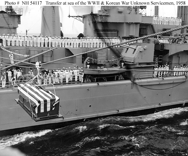
If you or someone else can identify the 4 radars in the photo below and advise as to the RPMs and type scan, such as oscillated up/dn as the rotated it would be a big help.Guest wrote:The SPG-49s did rotate around the horizontal axis to adjust the elevation. They also had the ability to oscillate back and forth around the vertical axis. The Talos tracking antennas operated independently in bearing and elevation from the launcher. The missiles were fired and guided to a predicted intercept point ahead of the target.
Phil
Thanks
http://www.nulspace.com/hobbies/boston/ ... 21813c.jpg
Build em big
-
Cliffy B

- Posts: 3125
- Joined: Sun Feb 01, 2009 3:55 pm
- Location: Hawaii
- Contact:
Re: Calling all CAG-1 USS Boston Fans!
Best guess from me is:
Fore to aft:
SPS-8
CXRX
SPS-43
SPS-10 under the -8 and I "think" a SPS-12 hiding under it. Need a better photo to be sure. If I'm remembering correctly she had some spare 2D air search sets on board in the early years.
Mk-13 on the Mk-34 director and Mk-25 on the Mk-37 director. Mk-56 director below the SPS-43. SPQ-5 Terrier Illuminators.
Drawing Board:
1/700 Whiff USS Leyte and escorts 1984
1/700 Whiff USN Modernized CAs 1984
1/700 Whiff ASW Showdown - FFs vs SSGN 1984
Slipway:
1/700 Whiff USN ASW Hunter Killer Group Dio 1984
1/700 Whiff USS Leyte and escorts 1984
1/700 Whiff USN Modernized CAs 1984
1/700 Whiff ASW Showdown - FFs vs SSGN 1984
Slipway:
1/700 Whiff USN ASW Hunter Killer Group Dio 1984
-
CAG-1NUT
- Posts: 112
- Joined: Fri Jan 16, 2015 3:12 pm
- Location: Spotsylvania, Va. U.S.A.
Re: Calling all CAG-1 USS Boston Fans!
Thanks and I found this site with list of the different types with data and photos, but no mention of RPM go fig! http://en.wikipedia.org/wiki/AN/SPS-48Cliffy B wrote:Best guess from me is:
Fore to aft:
SPS-8
CXRX
SPS-43
SPS-10 under the -8 and I "think" a SPS-12 hiding under it. Need a better photo to be sure. If I'm remembering correctly she had some spare 2D air search sets on board in the early years.
Mk-13 on the Mk-34 director and Mk-25 on the Mk-37 director. Mk-56 director below the SPS-43. SPQ-5 Terrier Illuminators.
http://en.wikipedia.org/wiki/List_of_radars
Build em big
-
DrPR
- Posts: 1689
- Joined: Sun Mar 07, 2010 12:01 am
- Location: Corvallis, Oregon, USA
- Contact:
Re: Calling all CAG-1 USS Boston Fans!
The AN/SPS-10 had a nominal rotation or 16 revolutions per minute +/- 1 RPM. The AN/SPS-10B had a nominal rotation of 15 RPM. It did not tilt up/down. Antennas rotated clockwise.
The Mk 16 radar antenna (part of the Mk 25 radar) on the Mk 37 director did not rotate - it turned with the whole director. It could be tilted up/down but this was necessary only if a target flew close in and over the ship.
Directors could rotate clockwise and counterclockwise. The antennas could be tilted up/down a bit, but only to track very close targets at high altitudes. Normally they pointed directly at targets and didn't move much at all. The fastest movement was when initiating a target search and rotating from the stowed centerline position to point in the direction of the target. However, the missile directors were often pointed straight up during testing so the radiated energy wouldn't illuminate other ships/aircraft or pose a hazard to personnel on the ship.
Phil
A collision at sea will ruin your entire day. Aristotle
-
CAG-1NUT
- Posts: 112
- Joined: Fri Jan 16, 2015 3:12 pm
- Location: Spotsylvania, Va. U.S.A.
Re: Calling all CAG-1 USS Boston Fans!
Thanks, that's what I wanted to know!!!!!DrPR wrote:The AN/SPS-10 had a nominal rotation or 16 revolutions per minute +/- 1 RPM. The AN/SPS-10B had a nominal rotation of 15 RPM. It did not tilt up/down. Antennas rotated clockwise.
The Mk 16 radar antenna (part of the Mk 25 radar) on the Mk 37 director did not rotate - it turned with the whole director. It could be tilted up/down but this was necessary only if a target flew close in and over the ship.
Directors could rotate clockwise and counterclockwise. The antennas could be tilted up/down a bit, but only to track very close targets at high altitudes. Normally they pointed directly at targets and didn't move much at all. The fastest movement was when initiating a target search and rotating from the stowed centerline position to point in the direction of the target. However, the missile directors were often pointed straight up during testing so the radiated energy wouldn't illuminate other ships/aircraft or pose a hazard to personnel on the ship.
Phil
Build em big
-
CAG-1NUT
- Posts: 112
- Joined: Fri Jan 16, 2015 3:12 pm
- Location: Spotsylvania, Va. U.S.A.
main gun and bow discrepancies?
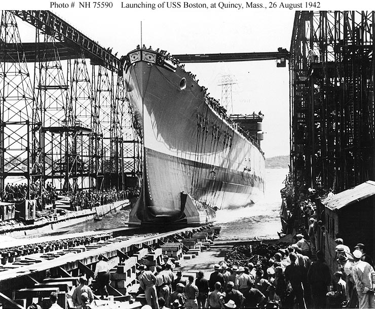
Whereas I built the hull buck for my 1/96 scale Boston CAG-1 per drawings from the floating dry-dock and found that do not match the splendid model covered here. For one the bow has a bulbous bottom as can clearly be seen in the photo below. Was it changed at some point as depicted in the model, should I change mine?
http://www.navsource.org/archives/04/069/0406909.jpg
Also the Main gun turrets do not match those on the model. whereas the the front corners not break sharply, but smoothly and into a long curve as seen the files below. Were these change also or are the turrets wrong for the ship?
http://www.navsource.org/archives/04/067/04010816.jpg
http://www.navsource.org/archives/04/069/04010176.jpg
http://www.navsource.org/archives/04/069/04010107.jpg
With respect to the bow, I suppose it could have been changed, especially after say, damage. As for the main battery, I doubt such a major modification would have been made. I'm not trying to rain in anyone's parade, I just want to build mine right.
Build em big
-
DrPR
- Posts: 1689
- Joined: Sun Mar 07, 2010 12:01 am
- Location: Corvallis, Oregon, USA
- Contact:
Re: main gun and bow discrepancies?
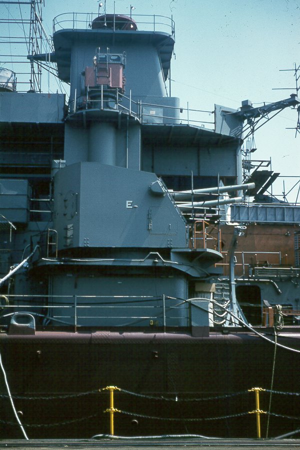
The picture is the Topeka CLG-8.
The three dual 5"/38 mounts mean it was either the Topeka CLG-8 or the Galveston CLG-3. The other CLGs had only one 5"/38 mount. The Topeka had a tripod fore mast as in the photo. The Galveston had a four-tube forward radar tower.
Phil
The three dual 5"/38 mounts mean it was either the Topeka CLG-8 or the Galveston CLG-3. The other CLGs had only one 5"/38 mount. The Topeka had a tripod fore mast as in the photo. The Galveston had a four-tube forward radar tower.
Phil
A collision at sea will ruin your entire day. Aristotle
-
CAG-1NUT
- Posts: 112
- Joined: Fri Jan 16, 2015 3:12 pm
- Location: Spotsylvania, Va. U.S.A.
Re: main gun and bow discrepancies?
Thanks guys. My hull has the bulbous bottom, so I'm OK there and was not ready for the main guns yet. Those Navy photos were supposed to be the Boston!
Build em big
-
CAG-1NUT
- Posts: 112
- Joined: Fri Jan 16, 2015 3:12 pm
- Location: Spotsylvania, Va. U.S.A.
Re: more progress
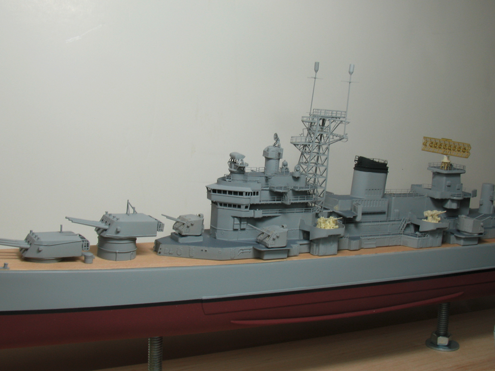
It's an old post, thus you likely have your answer about the chutes. If not, could be simply because the port and starboard 5" DPs are less likely to eject shell casings at the crew than the forward 5". Whereas, the fwd 5" can fire off either beam and thus send casing everywhere. I probably wrong, but that's my take in it.RandyM wrote:I finished the main and secondary gun armament (8" and 5" turrets), plus some directors and some additional inner railing/ladders. I'm also comparing the 3"/50 gun mounts from both Yankee Modelworks (kit-supplied - on the after mount) and Veteran (on the fore mount). No detail paint yet... just gallons and gallons of haze grey.
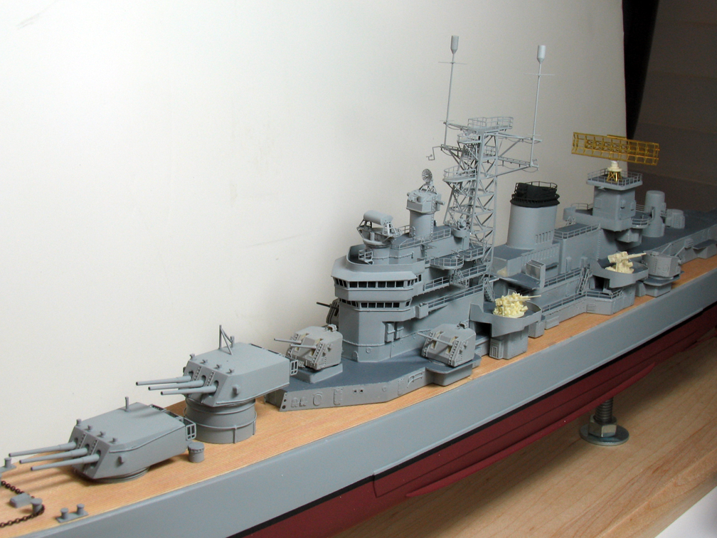
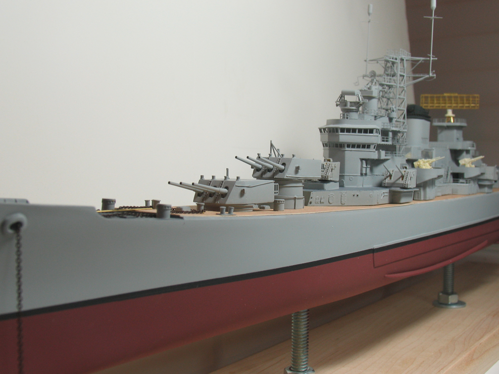
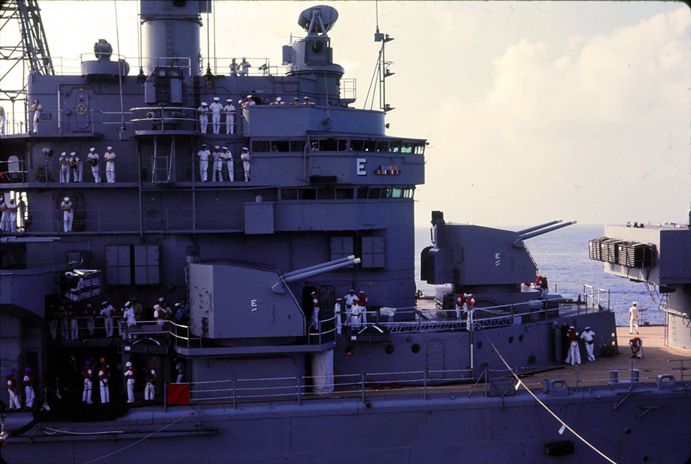
One (of many) thing I've not been able to figure out yet - the forward 5" mount on Boston had what I believe are shell ejection chutes on the back of the turret (you can just see one of them in the last image above, and clearly see them on the prototype in the image below), while the other four mounts did not. Why?
Question,where are the red/green navigation lights on the Boston? I can't find them on the model. Is that black areabelow and to the left of the ship's ribbons on the wing of the upper enclosed bridge deck the starboard light? Checkout the photo of the Boston's superstructure above. Whereas my 1/96 RC CAG-1 is getting search lights +, I need to wire them in now. Thanks
Build em big
-
DrPR
- Posts: 1689
- Joined: Sun Mar 07, 2010 12:01 am
- Location: Corvallis, Oregon, USA
- Contact:
Re: Calling all CAG-1 USS Boston Fans!
The black rectangle in the picture to the left of the ribbons is the starboard running lilght.
One possible reason for the shell ejection chutes on the forward 5"/38 mount is to prevent the ejected shells from banging into the superstructure and chipping off the paint.
Phil
One possible reason for the shell ejection chutes on the forward 5"/38 mount is to prevent the ejected shells from banging into the superstructure and chipping off the paint.
Phil
A collision at sea will ruin your entire day. Aristotle
-
CAG-1NUT
- Posts: 112
- Joined: Fri Jan 16, 2015 3:12 pm
- Location: Spotsylvania, Va. U.S.A.
Re: Calling all CAG-1 USS Boston Fans!
Another question, well, two actually.
Question 1: In the link below below, on the left side of the upper most platform/deck we see a mounting for what looks like an antenna. Should I add it to my Boston -as she was in Nam? Photo was taken May 1960.
http://www.navsource.org/archives/04/069/04010110.jpg
Question 2: In the 2nd link, top right, there's round platform, to right of the 3" gun director. It has X bracing with gussets. Photo was taken in 1958 I made mine look like that one. Is it correct the Nam era? Did they change to the version in the kit? See link 3 below. BTW what belongs on that round platform?
link 2
http://www.navsource.org/archives/04/069/04010119.jpg
link 3 below checkout photos 3 & 4 of RandyM's beautiful model.
viewtopic.php?f=48&t=76040&start=80
Thanks a lot for the help.
Build em big
-
CAG-1NUT
- Posts: 112
- Joined: Fri Jan 16, 2015 3:12 pm
- Location: Spotsylvania, Va. U.S.A.
what is type and MK # 3" directors
For my 1/96 CAG-1, I can't seem to find enough views to build the gun directors for the 3" guns. I'm sure I can find more info if had the type and MK #. At the top of the photo, it's the units directly below the U in the word Unknown in the link.
http://www.navsource.org/archives/04/069/04010119.jpg
Any help appreciated.
http://www.navsource.org/archives/04/069/04010119.jpg
Any help appreciated.
Build em big
-
Dick J

- Posts: 1991
- Joined: Mon Aug 06, 2007 6:29 pm