The Ship Model Forum

The Ship Modelers Source
It is currently Sat Jun 07, 2025 12:45 pm

All times are UTC - 6 hours [ DST ]


Post new topic Reply to topic  [ 2115 posts ]  Go to page Previous  1 ... 79, 80, 81, 82, 83, 84, 85 ... 106  Next
Author Message
PostPosted: Thu Sep 10, 2015 9:52 pm 
Offline

Joined: Thu May 29, 2008 8:02 pm
Posts: 3840
Max,

Try Googling "USN 1/350 scale hull numbers" ... Floating Drydocks carries Gold Medal Models decals


Top
 Profile  
Reply with quote  
PostPosted: Fri Sep 11, 2015 3:49 am 
Thank you, Rick.

I just bought your book on round bridge Fletchers. Very nice. I want to build this Tamiya model both accurately and with lots of detaill, so have also purchased several railing/radar/equipment photoetched sets and several different crew sets. I now have decals coming.

To everybody interested in these bouncy rolly ships.

I also plan on building my ship, USS Hugh Purvis, DD709, from the Dragon Gearing kit by shortening the hull (Sumners were called short hulls as the Gearings added 14 feet or so for extra fuel capacity thus range.

If you really want to get into WWII US Destroyers, I highly recommend the book "United States Destroyer Operations in World War II", by Theodore Roscoe. Published by United States Naval Institute, Annapolis, Maryland. I bought my copy at the BX in Newport, RI, in 1969. Lots of photos and excellent drawings by Lieutenant Commander Fred Freeman, U.S.N.R.

This book will fire you up about tin cans/greyhounds of the sea.

I am not sure just how detailed I want go go but being an ex. chief of damage control, want all the fire hoses and related equipment at least. Floater nets, railings, radars, etc. in photo etched within reason. I mean, of course the gun tubs and similar things are too thick for scale but I can live with that. Since I am going for a waterline in the ocean display, I can skip many of the underwater openings and the screws and rudder but may want to add a few holes in the side where drains and pump outlets are.

I am a professional model builder for over 40 years by the way but I still suck at realistic water. Will try again best of luck. :)

Max Corey, MM2, currently adding brass gun barrels (Alliance Model Works and they are too skinny but better than the kit ones) to the mounts


Top
  
Reply with quote  
PostPosted: Fri Sep 11, 2015 11:13 am 
Offline

Joined: Thu May 29, 2008 8:02 pm
Posts: 3840
Max,

Many guys replace the Tamiya kit 5-in mounts with aftermarket ones, because they are under scale.


Top
 Profile  
Reply with quote  
PostPosted: Mon Sep 14, 2015 5:37 pm 
The US Navy runs on bunker C and coffee. Well sure back then, cigarettes dirt cheap cuz you are a sailor.

I feel very proud of my service aboard DD 709. I have walked the decks of the Fletcher, which I think has the same basic power plant as the
Sumners and Gearings. Babcock and Wilcox. Fourteen foot bronze props at over 300 rpm. Sixty thousand horsepower and, as a snipe at the throttle board, a dumb teenager from LA, an opportunity.

The Fletchers featured air-encased boilers producing steam at 600 psi (4,100 kPa) and 850 °F (454 °C) 850 °F, with 2 emergency diesel generators providing 80 kW of electric power. Typically, Babcock & Wilcox boilers and General Electric geared steam turbines were equipped, although other designs and manufacturers were probably used to maximize the rate of production. The stea, turbines were Parsons and Curtiss.

The Huey P had Parsons turbines. Do you realize how many steam turbines are on a little ship like a DD? Seventeen steam turbines. Ok. Main propulsion has six.

The forward engine room between boiler rooms one and two, had a high pressure and a low pressure (ours were General Electric) turbine and a
cruising smaller turbine for running long distances on minimal fuel. Each electric generator has one so now we are at eight. The high pressure
air that is for gas ejection after firing the guns is nine. Then both enginerooms have two main feed pumps, two booster pumps and two
circulating pumps. That is 15.

Each engineroom has a bilge pump, a recripocating steam pump. 17. Cleaning the basket strainers on the bilge pumps was alway interesting at best.

I was a stupid teenager turning 21. Good luck, kid. I did ok.

Reading "Fletcher Class Destroyers" by Lester Abby. Good photos and models. I love looking at models of any kind by the way.

The sheer line of the Tamaya Fletcher is not that off, actually. Lots of photo etched details. So how the heck DO I slice off depth charges from plastic rod in same lengths like Loren Perry suggests. I think a jig. Still, a real depth charge has a flanged end with a fuse in the center as I recall. I will try. The kit ones look ok.

Max having fun with destroyers again.

Good men, America's best. We were ALL niave.


Top
  
Reply with quote  
PostPosted: Thu Sep 24, 2015 2:06 pm 
Offline

Joined: Tue Sep 15, 2009 12:02 pm
Posts: 69
Hi,
Can the O'BANNON can be built out of the 1/144 Revell kit?
If so, anyone makes a one quad 1.1-in mount in this scale?
What else would be needed to do her in the ´43 config?

Thanks

_________________
Eli Raphael
http://www.zotzdecals.net


Top
 Profile  
Reply with quote  
PostPosted: Thu Sep 24, 2015 5:39 pm 
Offline

Joined: Thu May 29, 2008 8:02 pm
Posts: 3840
An O'BANNON (along with NICHOLAS and CHEVALIER) can be modeled as long as you find a quad 1.1-in mount. I thought one was made by an Aftermarket Supplier. Try Googling "1/144 scale quad 1.1-in mounts".

By 1943 O'BANNON had four 20-mm guns added ... one atop the pilothouse, and three on the fantail without a bulwark around them ... and a BL "stovepipe" antenna on the foremast.


Top
 Profile  
Reply with quote  
PostPosted: Thu Sep 24, 2015 5:47 pm 
Offline

Joined: Tue Sep 15, 2009 12:02 pm
Posts: 69
Thanks Rick.
Was the quad deleted and a twin 40mm placed instead (1943)?

_________________
Eli Raphael
http://www.zotzdecals.net


Top
 Profile  
Reply with quote  
PostPosted: Fri Sep 25, 2015 9:39 am 
Offline

Joined: Tue Sep 15, 2009 12:02 pm
Posts: 69
I guess that building the O'BANNON in 1/350 using the Tamiya kit will be easier and use the Revell kit to do the FLETCHER. Couldn't find a quad 1.1 in 1/144.
Thanks.

_________________
Eli Raphael
http://www.zotzdecals.net


Top
 Profile  
Reply with quote  
PostPosted: Fri Sep 25, 2015 12:58 pm 
Offline

Joined: Thu May 29, 2008 8:02 pm
Posts: 3840
CHEVALIER was lost with the quad 1.1-in mount. NICHOLAS and O'BANNON were upgraded in late 1943 to the five twin 40-mm mount configuration.

I swore someone was producing a quad 1.1-in mount besides HR. HR Fittings has one ... http://www.hrprod.com/144.html ... but, some of their products are crude and they are slow on shipping orders.


Top
 Profile  
Reply with quote  
PostPosted: Fri Sep 25, 2015 1:04 pm 
Offline

Joined: Tue Sep 15, 2009 12:02 pm
Posts: 69
Hi Rick,
Got your book, excellent I might say.
If I go with the '43 refit and forget about the 1.1 quad, could you point out where were the twins 40s mounted on O'BANNON?

_________________
Eli Raphael
http://www.zotzdecals.net


Top
 Profile  
Reply with quote  
PostPosted: Fri Sep 25, 2015 5:32 pm 
Offline

Joined: Thu May 29, 2008 8:02 pm
Posts: 3840
That's going to be a lot of work ... scratch-building quite a few details. Look in my book in the section for "Five Twin 40-mm Mounts", there are many photos of the basic layout. FLETCHER, NICHOLAS, La VALLETTE, and JENKINS all had similar 10-40mm refits to O'BANNON at Mare Island with a MINY D-shape type "Tub" for the aft 40-mm gun between 53 and 54 mounts. Images specific to O'BANNON are available on Navsource under the DD-450 O'BANNON page.


Top
 Profile  
Reply with quote  
PostPosted: Mon Sep 28, 2015 4:02 pm 
Hello.

I was being stupid again. If I recall when we were alongside the Fletcher, she had two quad forties just ahead of the aft stack and I have a set of blueprint drawings that show this. I realize that all ships were installing anti aircraft guns at every refit because airplanes can sink any ship. Poor Laffey.

But is this correct? I want to build Fletcher as she was when I was aboard. I do not recall any Fram stuff like VDS or smaller torpedo tubes, only the quads and also so many medals and awards the bridge had extensions to fit them on.

I will have to do a lot of guesswork as to antennas, radars, etc.

I was wrong about steam turbines. I do have photos of my Huey P's enginerooms and books on her plant. Yes, I was also a snipe. I count 23 steam turbines in all. I was not an Electician's Mate so can only guess as to big electric motors for things like fuel pumps and ventilation fans, etc.

When I went to Machinist's Mate A school in Great Lakes, Ill, in 1968, I was taught that the Fletchers and Sumner/Gearings had the same basic steam plant. The DEs like Rudderows used the turbo-electrics with big electric motors on the main propulsion shafts. I was trained on those as well.

As I look at these photo etched sheets from Gold Medal Models I kept wondering what the TINY hand wheels are for. Now I know, the orlikons.

So my biggest question is, as I look these kits and photo etch and rosin kits over, ... how the heck do I deal with such tiny parts? For example, how do I pick up this TINY hand wheel and make a shaft for it and install it on a TINY 20mm Orlikon? Trial and error. This should be good for a laugh or two.

Max and old mm having fun with the Navy again.


Top
  
Reply with quote  
PostPosted: Mon Sep 28, 2015 11:07 pm 
Offline

Joined: Thu May 29, 2008 8:02 pm
Posts: 3840
Not sure if you are Max or someone else Guest,

Anyway, FLETCHER had several configurations during her career ... which year are you interested in modeling her for?

During WWII she started out with one twin 40-mm mount in early July 1942. Then a second one was installed on her fantail in late August 1942. In July 1943 she was upgraded to the standard five twin 40-mm mounts with seven single 20-mm guns.

FLETCHER did get the Anti-Kamikaze Mod for an armament of five 5-in, two quad and three twin 40-mm mounts, six twin 20-mm mounts, and one quint torpedo tube mount in late 1945. But, she never returned to the war zone in this configuration having completed it after the war ended and was mothballed in it. In 1949 she was taken out of mothballs and converted to a DDE with only two 5-in guns and two TWIN 3-in mounts and a Mk 15 trainable hedgehog and four fixed ASW torpedo tubes in the aft deckhouse ... two per side. Later the Mk 15 HH was replaced with a Mk 109 ASW Rocket launcher. FLETCHER wasn't one of the three FLETCHER DDE conversions to get FRAM II mods. In 1969 FLETCHER was in the DDE configuration ... no 40-mm guns. Actually by 1969 none of the FLETCHERS still in service had any 40-mm guns left onboard.

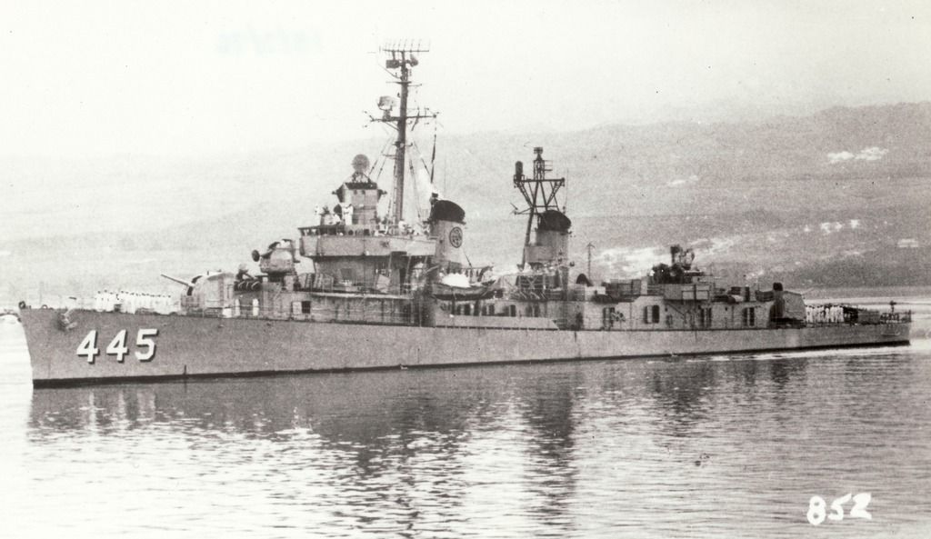
In 1969 FLETCHER would have looked pretty as seen in this image from about 1957. The differences would be in the ECM suite and more whip antennas. The other twin 3-in gun mount is on the starboard side staggered aft of the one you see here. Navsource.org has more images of FLETCHER.

Image


Top
 Profile  
Reply with quote  
PostPosted: Sun Oct 25, 2015 11:09 pm 
Offline

Joined: Sun Mar 14, 2010 2:32 pm
Posts: 404
Does anyone have any good pics or dimensions on the 40mm Bofors spare barrel lockers carried by Fletchers and others? It turns out that Heerman, the ship I'm doing some conversion parts for, appears to have had ready service lockers on one side of her after deckhouse and 40mm tub and what looks like a spare barrel locker on the other. Anyway, it looks like it could be a spare barrel locker.

Many thanks,

Bob


Top
 Profile  
Reply with quote  
PostPosted: Mon Oct 26, 2015 5:41 am 
Offline

Joined: Thu May 29, 2008 8:02 pm
Posts: 3840
Bob,

For which timeframe are you modeling HEERMANN? Here is a view of a sister to HEERMANN that should be the same configuration, as built. But there are no dimensions. Not sure what you mean by ready service lockers on the other side?

I'm on the road away from my iMac and it is harder to pull up and modify images.


Attachments:
dwgDD534AftDeckhousecrop.lr.jpg
dwgDD534AftDeckhousecrop.lr.jpg [ 26.32 KiB | Viewed 5228 times ]
Top
 Profile  
Reply with quote  
PostPosted: Mon Oct 26, 2015 2:20 pm 
Offline

Joined: Sun Mar 14, 2010 2:32 pm
Posts: 404
Hi,

It looks somewhat like that. The gentleman who has asked for 1/144th Heerman parts sent me a few pics the other night. The long spare 40mm locker appears attached to the starboard side of the tear drop tub, while what could be 20mm ready service lockers are on the top of the deckhouse just inside that little thin splinter shielding or bulwark.

Heerman is interesting. She had a Mark 51 even though the Fletchers bookending her in the production like carried Mark 49s, one or two 'til 1945. Its hard to see, but the Mark 51 tub appears to have the shielding inside the railings, not outside like most others, and it doesn't look like canvas. A building photo shows her with the tear drop 40mm tub on the fantail, although by 1943 this had been traded in for the triple 20mm arrangement.

I'm doing her as at Samar.

Bob


Top
 Profile  
Reply with quote  
PostPosted: Mon Oct 26, 2015 4:40 pm 
Offline

Joined: Thu May 29, 2008 8:02 pm
Posts: 3840
I doubt that there would be 20-mm Ready Use Ammo boxes ON TOP of the aft deckhouse. That is way too far away from any of the 20-mm guns. Hard to tell what they stowed there.

Production of Mk 49 directors couldn't keep up with even the requirements for just the FLETCHERs, so you will see some units getting them and a few not.

As for the bulwark around the Mk 51, it looks like there are external bracing and a ring around midway for some reason ... maybe as a hand grab.


Top
 Profile  
Reply with quote  
PostPosted: Mon Oct 26, 2015 8:09 pm 
Offline

Joined: Sun Mar 14, 2010 2:32 pm
Posts: 404
Here are crops of some of the photos I was sent. The railings around the director tub are really noticeable, with the shielding inside the rails. I'd never seen quite that arrangement before. There are clearly some little lockers there that I'm interpreting as possible 20mm lockers, but I can't be sure. I agree, it would be an odd place for them.
Image


The next photo shows the long, spare 40mm barrel locker. At least, that's what I think it is.
Image


Bob

PS. Almost forgot. In the first photo, it looks as if the vertical rails or supports on the exterior of the Mark 5 tub extend below the tub. Its blurry, but thee are little "nubs" or something trailing below the tub right where the vertical supports would go. Odd, I've not seen that before.


Top
 Profile  
Reply with quote  
PostPosted: Mon Nov 02, 2015 11:04 pm 
Offline

Joined: Thu Oct 29, 2015 12:12 pm
Posts: 3
I just recently joined the ModelWarships Forum and was very glad to see the posts and support for the Fletcher class destroyers. My step father served during the Vietnam war aboard the USS Picking DD-685. This was my inspiration to follow naval history and pursue model ship building. Moving forward, I recently purchased Revel's 1/144 scale German destroyer as it was the easiest to use to build a post war configuration of the Picking as she appeared in 1968 and prior to her decommissioning in 1969.

I have been to Navsource to search for any and all photos of the Picking but I need help in finding detailed yard photos and any plans and drawings of the ship if they exist. I would appreciate any help and direction as I would like to build as close as possible an accurate model of the Picking.


Top
 Profile  
Reply with quote  
PostPosted: Tue Nov 03, 2015 7:19 pm 
Offline

Joined: Thu May 29, 2008 8:02 pm
Posts: 3840
First thing you will have to deal with in building USS PICKING, is to get or build a Square-Bridge. The Revell German 4-Gun destroyers were Round-Bridge with an enclosed bridge built around it. I believe a Plastic 3-D Printer produced bridge in 1/144 scale is either already available or will be soon. There are some other differences in the ASW weapons and sensors for USN and German 4-Gun FLETCHERS. But, you are right that the Revell Z-1 class kit is a good start in your quest.

I have made digital images of most of the Booklet of General Plans (BGP) at the National Archives, but no BGP plans for PICKING exist there. There are plans for some of her sisters in their 1968-69 configuration. A very quick search of the plans I have taken camera shots turned up views of DD-651 COGSWELL and DD-652 INGERSOLL and I have attached a sampling of images. If you need specific areas or items let me know and I'll hunt for them. The scale for some of the upgraded items installed, like the Mk 32 ASW torpedo tubes, are not well represented (as to scale) on these plans. PICKING was unique in the location of her Mk 32 torpedo tubes, they were installed forward of her waist twin 3-in mounts, not as shown on these drawings.

I have attached a view of PICKING taken some time in the 1965-68 period.

Image

Image

Image

Image

Image


Top
 Profile  
Reply with quote  
Display posts from previous:  Sort by  
Post new topic Reply to topic  [ 2115 posts ]  Go to page Previous  1 ... 79, 80, 81, 82, 83, 84, 85 ... 106  Next

All times are UTC - 6 hours [ DST ]


Who is online

Users browsing this forum: No registered users and 24 guests


You can post new topics in this forum
You can reply to topics in this forum
You cannot edit your posts in this forum
You cannot delete your posts in this forum
You cannot post attachments in this forum

Jump to:  
Powered by phpBB® Forum Software © phpBB Group