Curious, did the ammo chutes on the exterior of the tear drop tubs have openings in the bottom, and if so what shape were they? Also, how did they interface with the interior of the tub itself when in use? Were there holes in the tub/splinter shielding interior that the crew used to just dump used shell casings down, or some other place?
Many thanks,
Bob
Calling all Fletcher-class (DD-445) fans
Moderators: BB62vet, MartinJQuinn, Timmy C, Gernot, Olaf Held, Dan K, HMAS, ModelMonkey
-
Rick E Davis
- Posts: 3879
- Joined: Thu May 29, 2008 8:02 pm
Re: Calling all Fletcher class DD fans
Not sure which destroyers you are looking at. On some units the chutes were really external baskets for holding the spent rounds and clips. There were holes in the deck above at the bulwark edge for spent rounds to be "kicked" into as the gun crew had time. Others I have seen seem to have been external chutes that returned the spent rounds to the internal baskets as originally installed. I have not attempted to document which units had what in the way of spent round capture. Having the holes at the edges of the bulwark made it easier to get the spent rounds/clips off the deck. There were similar baskets (of several different designs) for the other twin 40-mm mounts, with the before the bridge units being external, but pretty much out of sight below the bulwark platform extensions.
-
BobbyT
- Posts: 3
- Joined: Thu Oct 29, 2015 12:12 pm
Re: Calling all Fletcher class DD fans
Thank you Rick for your post on the USS Picking. I did purchase some components like the square bridge and Mk 37 and Mk 56 directors from ModelMonkey - (thank you as well for your help and offer. I do plan on looking into the main 5" gun mounts).
In my research I know that the picking was the prototype for the SCB 74A modernization and basic configuration for many of the post war Fletchers. Picking would be one of a few that had a Unit Commanders cabin constructed aft of her main superstructure/bridge structure which would result in the loss of her starboard boat. Also her bridge enclosure was enlarged during her refits in the late 50's or early 60's.
A question I have - one of many.... I know some Fletcher destroyers had their 5" loading machines mover to their starboard side deck, did the Picking have this as well? Also, in viewing some photos of the Picking, what is the deck fixture located opposite of the 5" loader on the port side deck? In these photos the fixtures are covered with tarps which does not help when trying to build a detailed model. I found the Youtube video of the Picking and Mullany refueling and in this video the fixture on the port side is uncovered but is unrecognizable.
If you or anyone can give some insight here let me know please. Thanks again these posts have helped immensely.
Bobby T
-
Rick E Davis
- Posts: 3879
- Joined: Thu May 29, 2008 8:02 pm
Re: Calling all Fletcher class DD fans
Depending on which photos you are looking at and the date of the photos, I believe that the other object opposite the 5-in/38-cal practice loader (on the starboard side), is a 3-in/50-cal practice loader (on the portside). The photo of PICKING I posted shows the 5-in practice loader on the starboard side on the main deck below where the aft Torpedo Mount was originally located.
Actually about one in four FLETCHER's had the Unit Commander cabin/accommodations installed among the 82 units (non-DDE) recommissioned for the Korean War.
PICKING was one of the three units funded in FY51 (1 July 1950 to 30 June 1951) and first modified to the SCB 74A upgrade and started being modified before 1 July 1951, PICKING was the first completed in October 1951. Followed by USS ABBOT and USS BENHAM in November 1951.
The Open Navigation Bridge was covered with an overhead (first canvas and then with permanent structure) during the 1950s. Not truly "fully enclosed".
Here are a couple of cropped views of PICKING's Bridge and Midships area showing the 3-in practice loader dated 19 July 1968.
Good luck on your build!!!
- Attachments
-
-
-
BobbyT
- Posts: 3
- Joined: Thu Oct 29, 2015 12:12 pm
Re: Calling all Fletcher class DD fans
Rick,
I thought the object on the port side may have been a 3" practice loader. After searching the internet for any information on a 3" practice loading machine and not getting any results I thought maybe the thing was a myth! Have you or anyone come across any good photos or schematics of the loader?
Also, is there any sources of information on graphics - specific to squadron logos, service ribbons and such applied to the ship(s)?
Thanks again. The historical information along with the photos has been valuable.
-
Rick E Davis
- Posts: 3879
- Joined: Thu May 29, 2008 8:02 pm
Re: Calling all Fletcher class DD fans
Bobby,
Sorry I don't have any photos of USS PICKING showing a DesRon badge painted on the forward stack. The photos I have don't appear to show a DesRon badge in 1968 timeframe. There is a view of PICKING's ship badge on Navsource, but I doubt that was painted on her stack.
The ships service ribbons can be seen in the bridge view I posted, but at the distance the photo was taken, making them out is next to impossible.
A useful place to look is at the USS PICKING reunion website .... http://www.uss-picking.org/ .... these groups can have a wealth of info on their ship and PICKING is one of the better ones. They show several of her ship badges during her USN service. You may even be able to find someone who "was there" to help you if it isn't on the website.
Towards the end of their USN careers, the few remaining FLETCHERS changed DesRon organizations fairly frequently. So which unit she was assigned to in 1968, I don't know. I have in the back of my mind that PICKING was assigned to a Pacific Fleet DesRon unit with GEARING class destroyers.
-
aptivaboy
- Posts: 404
- Joined: Sun Mar 14, 2010 2:32 pm
Re: Calling all Fletcher class DD fans
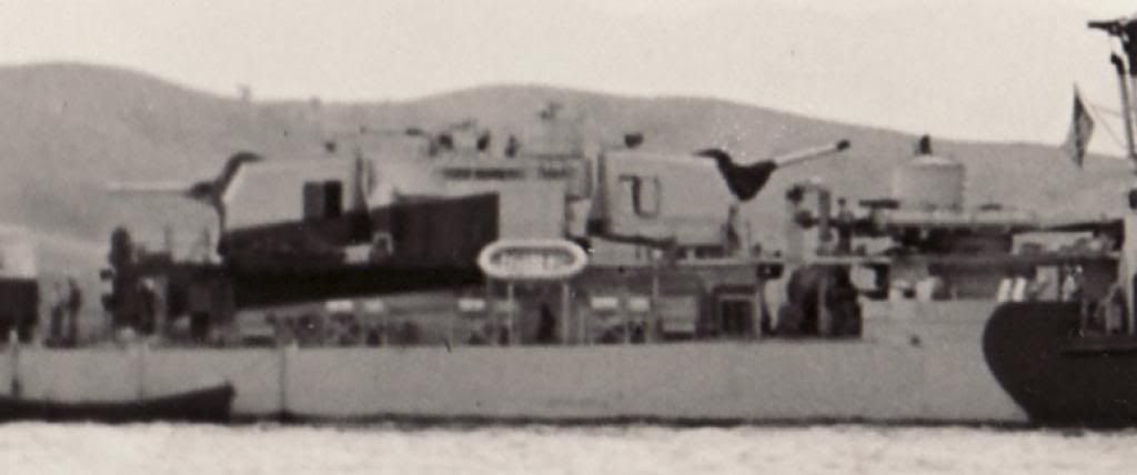
So, I'm looking at photos of Heerman and I'm perplexed about her forward 40mm tubs. I think they're the type with the flat sides, not the circular ones. From looking at the photo here, it seems like they're the flat sided type, but my old eyes can't quite tell. Can anyone tell for sure?

http://www.navsource.org/archives/05/0553203.jpg
Thanks,
Bob
http://www.navsource.org/archives/05/0553203.jpg
Thanks,
Bob
-
Rick E Davis
- Posts: 3879
- Joined: Thu May 29, 2008 8:02 pm
Re: Calling all Fletcher class DD fans
HEERMANN had the "smooth exterior with a flat on the onboard side" that was common to Bethlehem-built units and good many others as well.
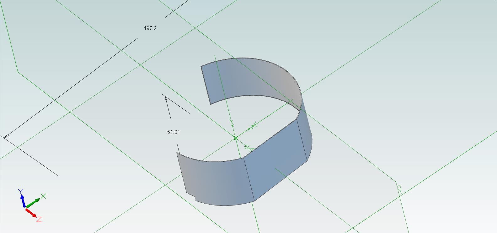
Here is the plan view of a drawing I came across at NARA. It was drawn for a Round-Bridge FLETCHER and has the exterior stiffeners, but the basic dimensions were standard on almost all installations of these forward mounts on FLETCHERS. Some units didn't maintain a circular shape to the bulwark inboard, Square-Bridge units normally wrapped the bulwark further inboard than seen here. Note that the "flat" area is kept 6-in from the side of the ship when complete.
Below it is a plan view of the same design used on BIW-built Square-Bridge units where the exterior of the bulwark is smooth and there are interior stiffeners. The dimensions and design are pretty much the same. This area on a real ship is quite complex with the super deck having sheer and camber.
Contact me off-line and I can send you the full size drawing with dimensions for ALL the parts used to build these on the real ships.
- Attachments
-
-
-
aptivaboy
- Posts: 404
- Joined: Sun Mar 14, 2010 2:32 pm
Re: Calling all Fletcher class DD fans
Evening!
Any idea if Heerman's tubs had the little drain holes at foot level in between the internal supports? I suspect they did, but in every photo of her with the 40mm tubs it isn't clear.
Many thanks,
Bob
PS. The work so far...
Any idea if Heerman's tubs had the little drain holes at foot level in between the internal supports? I suspect they did, but in every photo of her with the 40mm tubs it isn't clear.
Many thanks,
Bob
PS. The work so far...

-
aptivaboy
- Posts: 404
- Joined: Sun Mar 14, 2010 2:32 pm
Re: Calling all Fletcher class DD fans
PS. I might ask the same about her waist 20mm bulwarks. Looking at this photo from earlier in the thread...
...apart form that one little shadow underneath the after Oerlikon, there appear to be no drain holes. Were they not there, or just too small to show up in the photos? I've not been able to detect any other potential drain holes in photos of Heerman's 20mm bulwarks.
Thank you!
Bob

...apart form that one little shadow underneath the after Oerlikon, there appear to be no drain holes. Were they not there, or just too small to show up in the photos? I've not been able to detect any other potential drain holes in photos of Heerman's 20mm bulwarks.
Thank you!
Bob
-
Rick E Davis
- Posts: 3879
- Joined: Thu May 29, 2008 8:02 pm
Re: Calling all Fletcher class DD fans
Bob,
Sorry, I was busy on other things and then I spent some time looking for "during construction" photos of Bethlehem-built units and I couldn't find any good photo showing where the drain holes were located on the forward 40-mm "tubs". There had to be drains, likely right at the outboard deck edge (flat area) under the ready use ammo clips. The clips and the canvas covers hide any detail in that area once installed. In this scale, you may not need to bother. If you want to put them in, maybe one in each side of the flat area in the deck of the tub.
As for the amidships main deck 20-mm guns spray bulwark, there does appear to be only that one drain that aligns with the drain trough going off-board. I'll have to post a small overhead image when I can get to my other computer. There also appears to be a small drain square on the aft side of those bulwarks. Again pretty damn small, not sure it is worth duplicating.
-
aptivaboy
- Posts: 404
- Joined: Sun Mar 14, 2010 2:32 pm
Re: Calling all Fletcher class DD fans
I was looking at a photo of Mullany that you'd posted earlier in the thread, maybe around page 50 or 60?? DD-529 had no apparent drain holes for her 20mm bulwarks, and being just a few hull numbers off from Heerman and built in the same yard, I'm going to assume that not putting in drain holes, more or less, was a Bethlehem thing.
(Maybe Modelmonkey will do a Mullany bridge, hint, hint? That's a very unique look).
For the 40s, I haven't seen any, either. I'm wondering if they were not installed on the earlier square bridged units (perhaps just forgotten or an oversight), or if they're in the bottom of the tub and drain straight downwards. This way, they'd be hidden from most photos since they'd be underneath the tub overhang? Just an idea I'm toying with.
Bob
-
Rick E Davis
- Posts: 3879
- Joined: Thu May 29, 2008 8:02 pm
Re: Calling all Fletcher class DD fans
Bob,
That is my thoughts about the forward 40-mm "tubs". There needed to be drains or the tub would pool up water until it got past the bulwark. I suspect they are on the deck near the flat section of the bulwark. I simply don't know where or how many holes there were.
As for the 20-mm main deck bulwark, these images should help.
The first image shows the location of what I will call the "main drain" and what looks to be another smaller drain along the curved section of the bulwark. This could be something else however and it is so small I wouldn't worry about it.
The second image shows the location from an overhead view with the alignment with one of the deck drain troughs. On the FLETCHERS and many ships, there is a channel running along the edge of the deck at the edge of the hull. All water that drains off the deck is channelled into this system and then exited off the ship is several locations. Bethlehem located one of the drain off troughs with the drain through the bulwark. You will notice that the 20-mm bulwark breaks the drain trough and that there is another trough just ahead of the bulwark to drain water coming from further forward.
Depending on how anal a modeler is, they could go insane getting all these small details into their model.
- Attachments
-
-
-
aptivaboy
- Posts: 404
- Joined: Sun Mar 14, 2010 2:32 pm
Re: Calling all Fletcher class DD fans
Many thanks! Mullany has that same single drain, too, so that was how I was going to do the bulwarks.
Is there anything you don't have a picture of?
Bob
Is there anything you don't have a picture of?
Bob
-
Rick E Davis
- Posts: 3879
- Joined: Thu May 29, 2008 8:02 pm
Re: Calling all Fletcher class DD fans
I have over 4,000 images of FLETCHERS. But, there are a surprising number of them that were "camera shy" at some point in their career.
-
aptivaboy
- Posts: 404
- Joined: Sun Mar 14, 2010 2:32 pm
Re: Calling all Fletcher class DD fans
Any idea what the interior of Heerman's forward tubs looked like? Any internal supports or ammo racks? I'm assuming that there were supports but I've also run across pics of various gun tubs from various classes that are totally smooth, at least on the inside. Maybe the splinter shielding was thicker and didn't need the external bracing?
Many thanks,
Bob
Many thanks,
Bob
-
Rick E Davis
- Posts: 3879
- Joined: Thu May 29, 2008 8:02 pm
Re: Calling all Fletcher class DD fans
Bob,
I can't locate a view without the canvas covers over the ready ammo clips of the Bethlehem-SF built units, but there should be stiffeners on the inside. Rule of thumb was stiffeners were either on the inside or outside. They should follow the layout seen on the BIW Engineering drawing I posted a few posts back, with it looks like eight stiffeners.
I can't locate a view without the canvas covers over the ready ammo clips of the Bethlehem-SF built units, but there should be stiffeners on the inside. Rule of thumb was stiffeners were either on the inside or outside. They should follow the layout seen on the BIW Engineering drawing I posted a few posts back, with it looks like eight stiffeners.
- Attachments
-
-
aptivaboy
- Posts: 404
- Joined: Sun Mar 14, 2010 2:32 pm
Re: Calling all Fletcher class DD fans
I was looking at this photo (http://www.navsource.org/archives/05/0553119.jpg) and blew it up in Photoshop and sharpened it, resampled it, etc, and I can't see any supports in there. Ammo racks, yes but no supports. When I try to visualize and plot where the supports would be, they usually end up right in the middle of some of the racks. Hazelwood had the smooth exterior tubs like Heerman both before and after her large repair, yet I can't ID any internal supports. I must admit to being pretty puzzled (admittedly, it might be the wine!).
Bob
Bob
-
Rick E Davis
- Posts: 3879
- Joined: Thu May 29, 2008 8:02 pm
Re: Calling all Fletcher class DD fans
Bob,
Higher res images are the answer.
As you can see the stiffeners are more or less "integrated" into the clip holder stowage system. Also, this view shows that the late-war mod of having a pop-out hinged flap for the outboard flat of the "tub" has been installed and all the stowage clip holders removed from that area.
PS; Remember the question of if and WHERE a drain was for the forward 40-mm "tubs". Well in looking really close in the aft outside corner (I don't know how else to describe the location) where the flat section meets the aft curved bulwark. There it is with a floor drain cover. Much like in a restroom.
- Attachments
-
-
-
-
aptivaboy
- Posts: 404
- Joined: Sun Mar 14, 2010 2:32 pm
 Re: Calling all Fletcher class DD fans
That makes perfect sense now! Seriously, you are the best!
I was visualizing the supports as being flush with the inner shielding, but it looks like they stand proud of it. The large support to the right of the barrel attached to the flat side in the second pic looks like a standard support, triangular in shape. The ones on the circular part of the shielding almost look like upside down L-shaped supports, with the feet attaching to the shielding and the leg then proud of it. Does this interpretation sound feasible??
Bob