Dick J wrote:
I would like to make a couple of points while you are still early in the project.
Thanks! Your opinions and help are very valued!
Dick J wrote:
First, the MK-19 directors had two parts. The main director portion was on a circular raised platform as seen in this shot of Northampton.
http://www.navsource.org/archives/04/026/0402626.jpg Note that in this picture that the rangefinders are still absent from the semicircular projections of the deck that supports the raised platforms for the main part of the director. Similarly, on the Lexington's, the main portion of the director was on a raised circular platform. Two were in the center of the upper fore top. The rangefinders were in the lower outboard positions.
Agreed. From the perspective of the 3D model's design, as a general principle, there are some features of a 3D printed model that would be more realistically replicated by other materials. The
Lexington and
Saratoga bridge towers (because of the separate funnel, not sure that "island" is the more correct term for CV-2 class), are intended to provide the modeler with a good superstructure from which to add details that would not be 3D printable by Shapeways or look more to scale if made in another medium, PE or thin styrene, for example. While the cylindrical Mk.19 Director bases are certainly 3D printable, and their dimensions are generally known, the platform itself is too thin to print realistically. Therefore, I decided to omit the base and platform from the design leaving just subtle locator disks to aid the modeler. Having said that, the directors and their platforms are obviously important features of the ship and your comments are very helpful in informing the modeler what needs to be added and where it goes, and are most appreciated.
Dick J wrote:
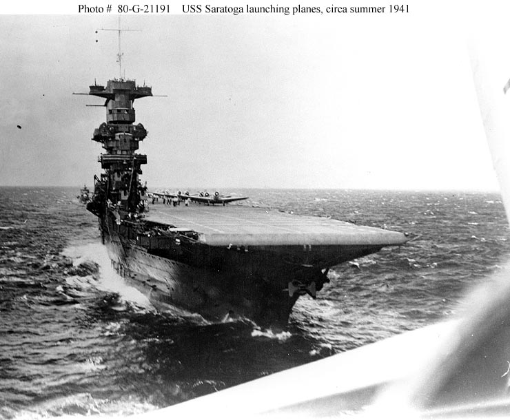
When the extension was added to the front of the upper top, it was at the level of the raised director platforms for the MK-19's. Saratoga had a similar extension after her 1941 refit, before it was all removed in 1942.
Agreed. This is a feature that I very much wanted to include and look right. While the height of the extension can be determined, documentation and photos of the shape, extents, dimensions and aft configuration in 2D form are absent. The absence of good 2D documentation was a struggle in developing an acceptable 3D design. Hopefully, better documentation will come forth. If it does, I will adjust the design.
Dick J wrote:
On the deck level for 8" gun turrets 2 and 3, the access to the turret was on the sides. Since the turrets were the width of the deckhouse, the deck was extended out on either side of the turrets. The outer corners were rounded except for the forward end of the extension to starboard of turret 2, which was beveled.
This is a feature captured in the 3D design.
Dick J wrote:
The deck did not extend forward of the deckhouse for turret 2 nor aft of the deckhouse for turret 3. There was no need there, and it would have interfered with turrets 1 and 4. Did they extend those decks to support the end bulwarks of the splinter screens? The photos are unclear on that point. So extending the decks fore and aft is an assumption on your part. (Not totally beyond reason, but not actually mentioned in the documentation.)
Respectfully disagree. While the 1936 & 1941 Booklets of General Plans for
Lexington are drawn with no fore-aft extension, the 1944 Booklet of General Plans for
Saratoga does show a measureable extension, as do numerous photos of both ships throughout their lives. The photos confirm
Sara's drawings as essentially correct and show that Lex's drawings are incorrect as built. Therefore, I have discounted
Lex's drawings of this feature in favor of
Sara's drawings and the numerous
Lexington and
Saratoga photos of these fore-aft extensions.
Lex: see Wiper's Warship Pictorial 33
USS Lexington CV-2, pages 11, 13, 14, 24, 30, and 31.
Sara: see Doyle's
USS Saratoga Squadron at Sea, pages 47, 49, 50, 54, 73, 77, 89, 103, 104, 111, 116, 131, 134, 135, 141, 151, and 156.
Dick J wrote:
Also, while the Lexington's staff requested that the flag level be enclosed with the bullet resistant glass, it is not clear if there was either the time or the materials on hand to do so. The last photo before she was sunk is all we have to go on, and what it really shows has been much debated. Just because the protected enclosure was requested doesn't mean the entire request was fulfilled. For all that we do know about her, there is still a lot that we still don't.
Agreed. Obviously, the 3D design has no clear features, but the openings are present. As discussed earlier in the thread, the shape and extents of the enclosure and window openings as 3D designed are the best approximation that can be made from the available, limited photographic and documentary evidence we now have. The available evidence was very carefully considered in the design. Dimensions of the enclosure and window openings were either extrapolated or interpolated from known dimensions. New features were logically oriented and joined to known, existing features (enclosure facets match and meet splinter shield facets, for example). In the absence of good facts, assumptions were made in order to complete a reasonable design. One of the beauties of 3D design is that should further evidence come forth, the designs can be adjusted to match new evidence.
It is now up to the modeler to determine if the Model Monkey design is more reasonably accurate than Trumpeter's and Fujimi's.


