SoftwareI have drawn with computers in 2D since 1987 starting with In*a*vision, a vector based program. I had no experience with CAD programs, 3D printers or making Photo Etch. So my first task was to trial CAD programs. I looked at Autodesk 123D, CorelCAD and Design CAD 3D max and attempted to draw a hull. This took me to looking at MeshLab and NetFabb to correct the STL files. I came to the conclusion that I wanted a program that was:
1. Vector Based
2. Could import JPEG’s
3. Rotate JPEG’s
4. Scale JPEG’s
5. Have a GetDistance command
I chose to go with CorelCAD and NetFabb, not the cheapest programs around but they meet my criteria for usage.
I also made full use of MS Excel to convert from feet and inches to mm in 1/700 scale. Using the GetDistance command on photos scaled to 1/700 you could measure something you know as a check and then measure a new item nearby. By using screen measurements with a plastic ruler of a known and of an unknown item, in Excel you could then ratio the two items and so get the size of the unknown bit. I kept Excel running constantly in the back ground. I also used Excel to go from mm in 1/700 scale to actual feet for sanity checks.
Attachment:
 Figure 10 Excel for Sizing Calculations.jpg [ 142.19 KiB | Viewed 6531 times ]
For all measurements I went to 1/1000 of a mm. If you think of Photo Etch, 0.1 mm is visible to the eye. By going to .000 mm any measurement error is invisible.
Test 1Not knowing the software or the capabilities of 3D printers I thought a simple test to establish some normals would be in order. So I made my first complete hull drawing, the boiler casing, conning tower, placed bollards and fairleads on the hull and a series of cowl ventilators. CorelCAD allows you to save as dwg files but to export stl files that the 3D printers use. The stl files were corrected in NetFabb prior to printing. As this was a test I did not want to use a commercial 3D print service such as Shapeways.
Finding a local printer turned into quite the search. I would up on a Dutch site that has coordinated many 3D printers on a worldwide basis by city. The printers are called Hubs and vary in the type of printer used, fees, accuracy and layer thickness. Find a 3D printer near you at
http://www.3dhubs.com/ and have a look around.
I wanted a quick test and so choose a local printer that used a Ultimaker 1 printer, PLA material with 60 micron layers and a 0.4 mm nozzle. PLA is Poly Lactic Acid and is derived from plant material, it is clear or coloured can detail well and the parts tend not to bend. 60 micron layers is medium resolution now a days. 16 or 20 micron is the ultra high resolution that some hubs can provide. But a successful print needs more than material and layer resolution. Turns out the nozzle diameter controls what size of object can be printed. If your part thickness is less than 0.4 mm, in this case, then the part either does not print or gets smeared. PLA is a thermoplastic, you heat it and it flows into position, cools and you get your part. If it cannot cool fast enough then you get smeared parts or slumps. So here is what the Ultimaker 1 can do.
Attachment:
 Figure 11 Test 1 in CorelCAD.jpg [ 42.97 KiB | Viewed 6531 times ]
Attachment:
 Figure 12 Test 1 from a Ultimaker 1 at 60 microns.jpg [ 91.37 KiB | Viewed 6531 times ]
So overall the shapes are correct but there is no detail. The midships bollard and fairleads did not even print.
Attachment:
 Figure 13 Test 1 Boiler Casing in CorelCAD and at 60 Microns.JPG [ 55.89 KiB | Viewed 6531 times ]
The skylights and funnel bases are not too bad but the portholes are missing and the doorways bleed upwards. The intakes are also smeared due to the nozzle size and layering. So this is OK for a fit check but 60 microns would create a lot of extra work to get a useable part.
Test 2Test 2 is from a second 3D printing Hub near Toronto, Rapid-Fab's Hub,
https://www.3dhubs.com/toronto/hubs/rapid-fab, that has a Projet 3510 with XHD mode using VisiJet Crystal material; this results in 16 micron layers and 0.025 – 0.05 mm part accuracy.
Printed and delivered with Canada Post shipping across Canada in 8 days, not bad service at all.
Attachment:
 Figure 14 Test 2 from a Projet 3510 at 16 Microns.jpg [ 61.25 KiB | Viewed 6531 times ]
Shapes are correct with hard edges. The layers can just be felt on the deck and the edges are slightly rough to the touch. Simple wet sanding will result in smooth deck surface, with a coat of varnish this should cast. The details are there as well with the bollards and fairleads accurately printed.
Attachment:
 Figure 15 Test 2 Boiler Casing at 16 Microns.jpg [ 78.69 KiB | Viewed 6531 times ]
The doorways are correct and the portholes are also now present and correct. The boiler air intakes are now correct and the cover supports tried to print. These need to be thickened slightly. This part also fit perfectly into position in the hull and is ready for casting with minimal cleanup.
Test 2 learning’s confirm that 3D printers have the printing resolution required for 1/700 scale projects. Not everything can be printed as shown by the supports but the cowl vents turned out OK so thicknesses of 0.05 mm should print. Looking at the hull I got the shear completely wrong. At this point the Amgram Navel Architects hull sections became available and so I decided to start over from scratch. As the VisiJet Crystal material seems quite brittle, I also decided to add pour stubs to the parts so that I could recast them in resin.
3D DrawingShip Boats
So to get further practice drawing I decided to make the ships boats next. This resulted in another learn curve but the results allowed me to redo the hull applying the lessons learned.
Attachment:
 Figure 16 Ship Boats Rendered.jpg [ 149.29 KiB | Viewed 6531 times ]
These I drew on pour plugs and also created outlines suitable for PE.
Attachment:
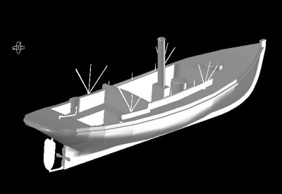 Figure 17 34 Ft Steam Cutter Rendered with PE Positioned.jpg [ 121.01 KiB | Viewed 6531 times ]
Here is an animated rendering with the PE mounted on the steam cutter. This to scale is about 15 mm long, theoretically it should print.
The Hull
The sections drawing was imported into CorelCAD and rotated so that it was perfectly horizontal and scaled so that full size is 1/700 in mm. The half sections where then redrawn and converted into full sections.
Two sections had to be generated by measurement and referenced to photos; the break to the main deck and just ahead of this where the bow flare ends.
In a second drawing the keel line that was imported, rotated and scaled to 1/700 mm. The sections were then Copied from the first drawing and pasted into the second drawing. The sections where then roughly positioned along the ‘keel’ line. Sections where then rotated 90° counterclockwise along there Y axis. Construction lines where drawn for each section along the keel to mark there exact location. The bottom middle of the sections where shifted into position along the keel line using the Move command.
Attachment:
 Figure 18 Hull Lines.jpg [ 65.93 KiB | Viewed 6531 times ]
After much trial and mostly error, lessons were learned. One, Polylines should only be used to draw sections. Two, Arcs should be used to join the sections along a horizontal plain. Three, Splines should be used to join sections that curve through 3D space.
Attachment:
 Figure 19 Hull Loft.jpg [ 79.78 KiB | Viewed 6531 times ]
By doing this you can loft between the Sections into a 3D solid. If the space is complex, then many small sections will have to be created so that the shape when lofted is correct, an example of this being the bow and stern. The sections where calculated by using construction lines to identify points in space. These were then formed into sections and connected with arcs. Individual sections where then lofted and the resulting solids joined with a union command.


 I should look more often in this part of the board!