To appease the neighbors, I avoid all noisy work in the evening. This is the time for designing, make drawings and plans, writing a service and operating manual, painting, and testing and building electronics.
In regards to electronics I needed three DC voltages. 24 volts for panel lamps and LED lighting. 12 volts for motors and relays, and 5 volts for digital logic circuits.
For this I had to build a power supply unit (PSU) which will be installed in the bridge console. From this PSU I can develop the rest of the circuitry.
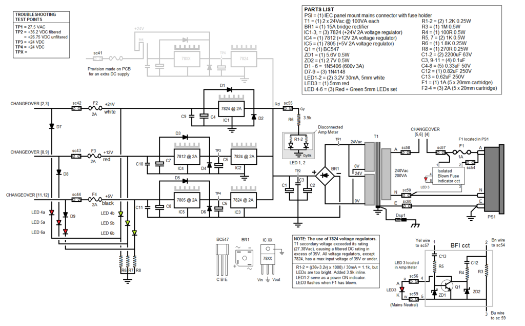
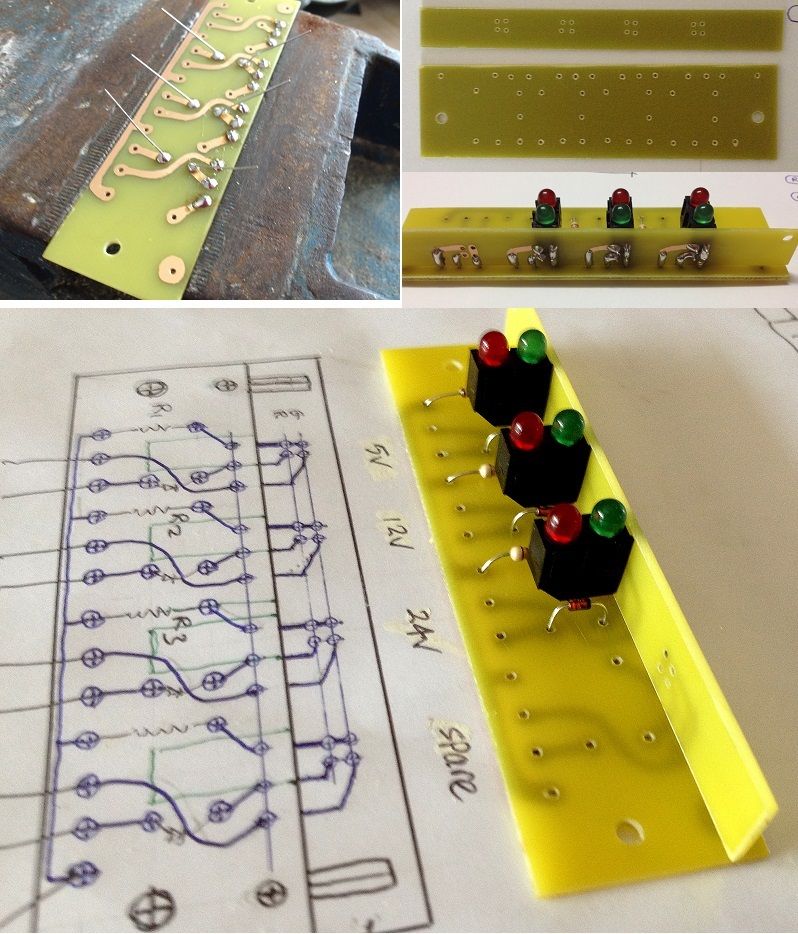
The PSU circuit diagram:
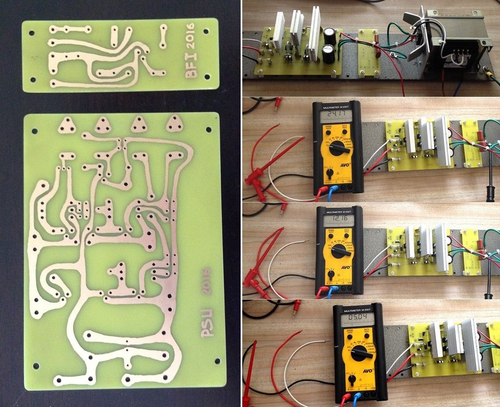
The printed circuit boards, assembled and tested. Each voltage source can handle 2 amps:
It was decided to replace the front panel of the console with a clear perspex sheet. This is to allow the museum visitors to view inside the console.
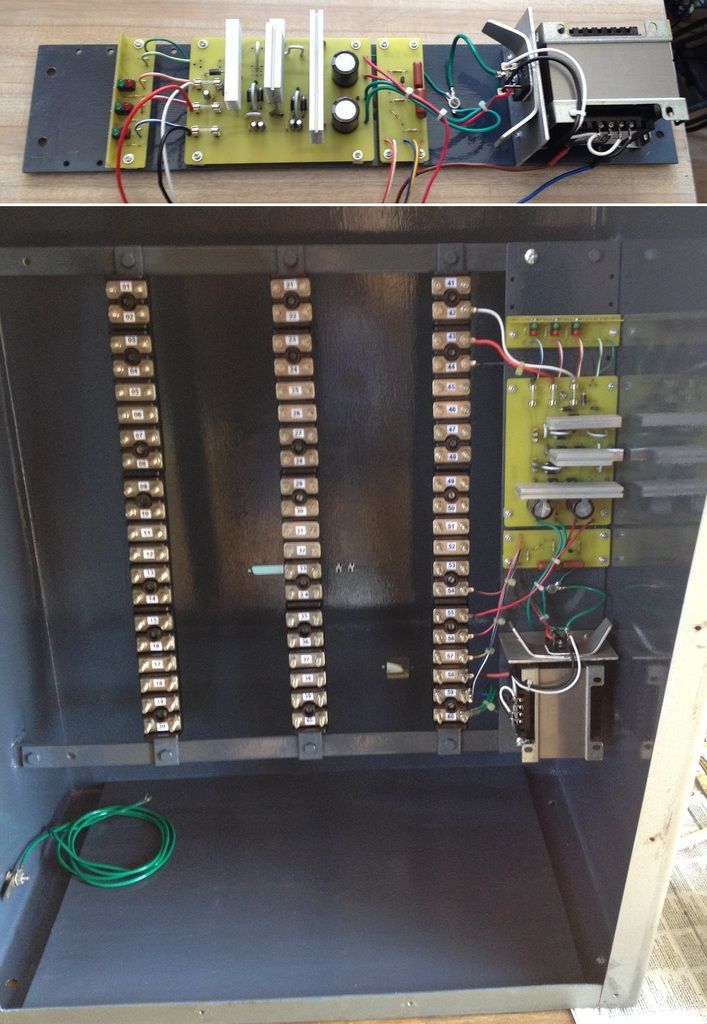
The console exterior will remain looking antiquated, except for the panel screws, which had to be replaced. The exterior has been rust treated and satin varnished. However, since the internals is anew, so too will the interior console surfaces. I decided to paint it a dark 'Boatshed' Grey. This will help to contrast the coloured wiring. So, the console interior will be a sort of 'lit' diorama.
To add extra lighting, to the interior, a blown fuse indicator circuit was added to the PSU. That is, while voltages are OK their output indicator will be a green light (LED). If that output fuse blows, the green indicator will go off and the red indicator goes on in its place.
Blown fuse indicator circuit board:
The main diorama will include sound effects, such as an warning bell before bridge operation, a fog horn, and a diesel/steam engine sound for the boat. The circuitry for this, and its speakers, will be installed within the console.
For speakers, I used a set from an old analogue TV set. However they needed a bracket for keeping its diaphragm from touching anything when mounted onto a surface:
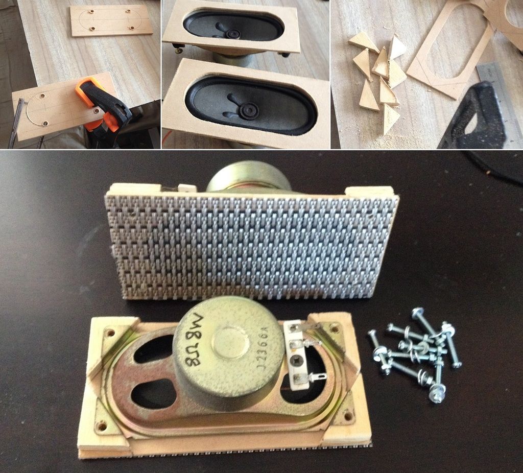
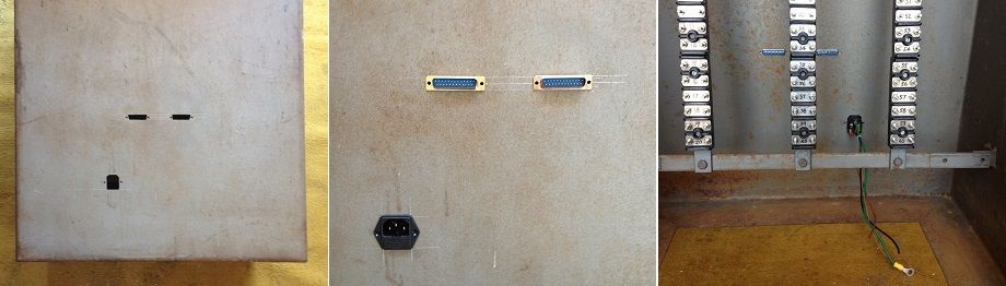
The console need slots to accommodate the speakers, connectors to (under table) control box, and power socket: