It has been again several months since I wrote something here. However, don’t think that nothing has happened since.
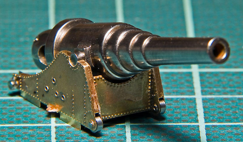
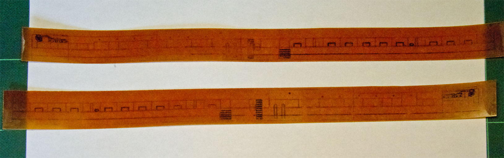
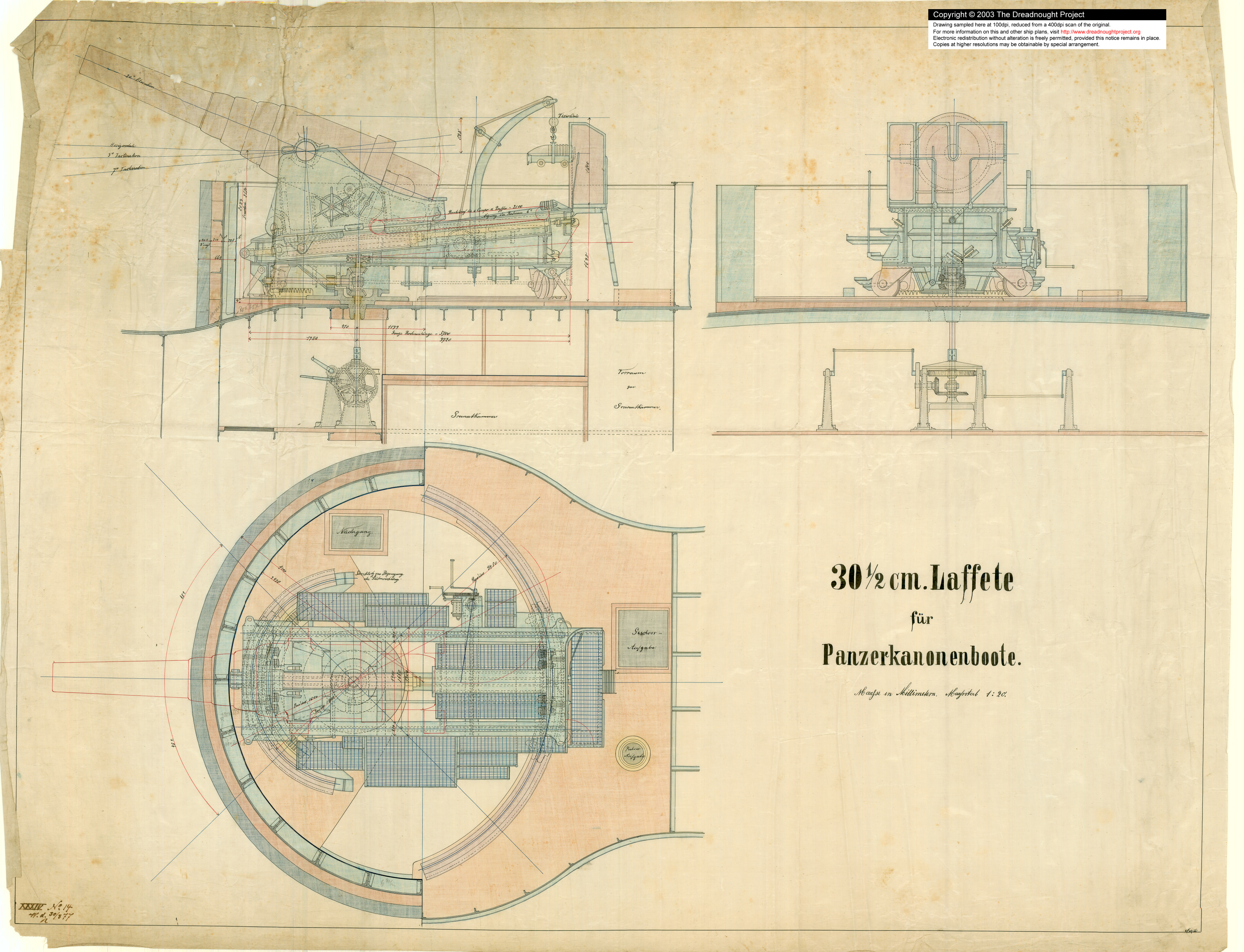
After the funnel I turned my attention to the lower carriage of the 30,5 cm-gun. This is a complex assembly of steel plates connected by L-beams and held together with rivets. Some years ago a detailed Imperial Admiralty plan appeared on the Internet:
http://www.dreadnoughtproject.org/plans/SM_Wespe_1894//305mm_laffete_100dpi.jpg (image too large)
Quelle: http://www.dreadnoughtproject.orgTogether with the description in a contemporary textbook (GALSTER, 1885) these drawings formed the basis of some reverse engineering. A problem with the above drawings is that many parts are drawing onto each other, semi-transparent and with dashed lines. Sorting out this maze into its three-dimensional element was not easy and some part will remain a matter of interpretation.
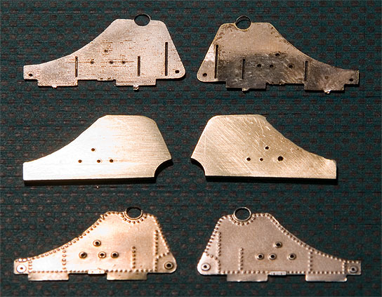
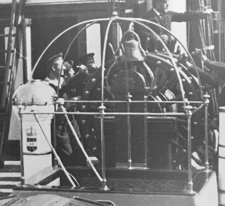
I had hoped to get away without etched parts. Trials with embossed styrene-sheet to simulate the rivetting, however, were not very successful. The embossing distorted the miniscule parts. The rivetting is very prominent and can be seen on a large demonstration model in the Naval Museum in Copenhagen or on some russian-kloned Krupp-carriages in the Suomenlinna fortress off Helsinki. The rivetting can be much more precisely rendered with etching and one avoids the added difficulty of having to cut out minute parts.
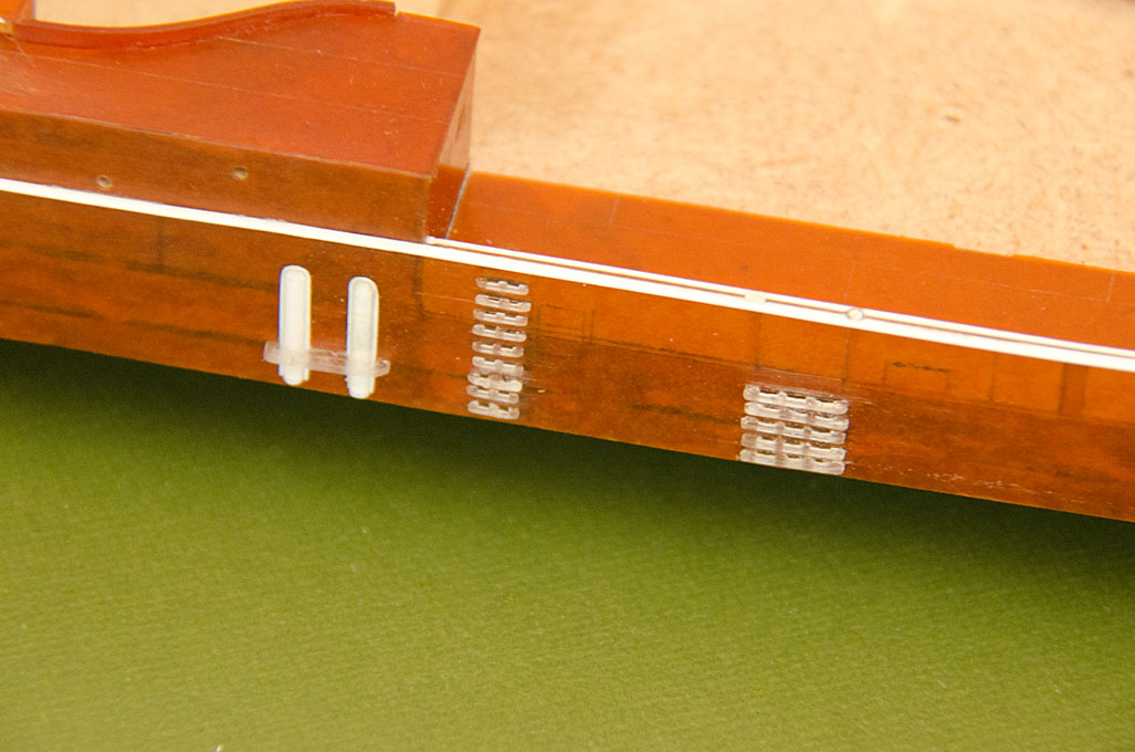
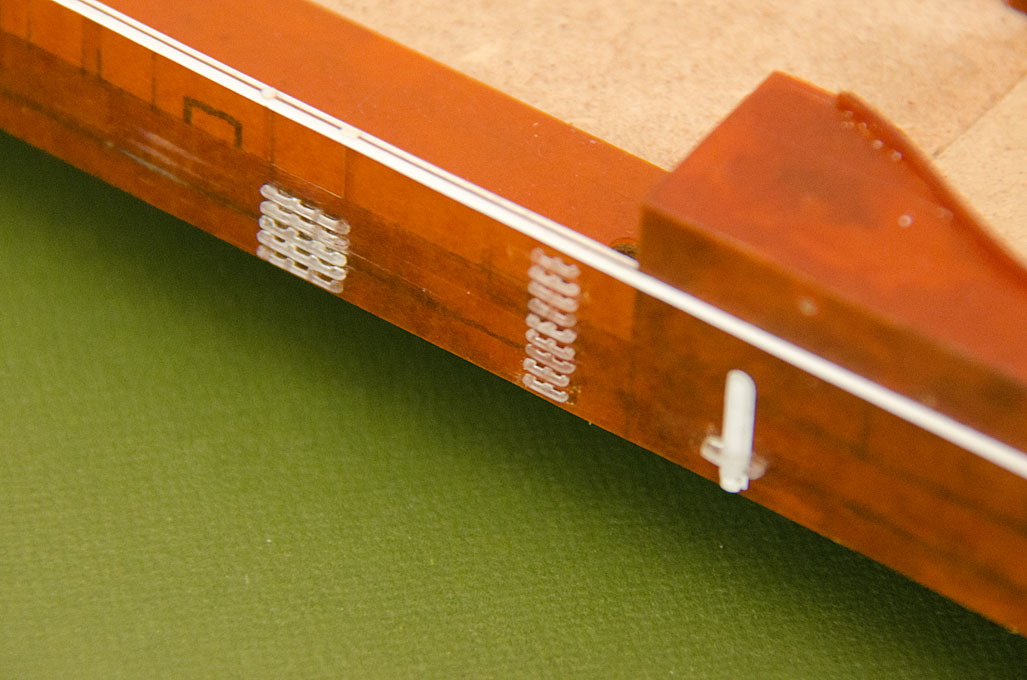
To begin with the frame of the carriage with sides and ribs from sheet-steel was designed. The L-shaped reinforcement profiles including their rivetting was then drawn. Next in the line was the housing of the training mechanism. I will not fully build this mechanism as it will not really be visible on the finished model. It will be only made in its rough shape that is needed to support the various axles and rods that will be visible. Also designed were the various parts of the hydraulic recoil mechanism and its linkage to the upper gun-carriage. Various other small parts, such as the housings for the sprung buffers that limit the movement of the upper carriage, were designed as etched parts to be folded.
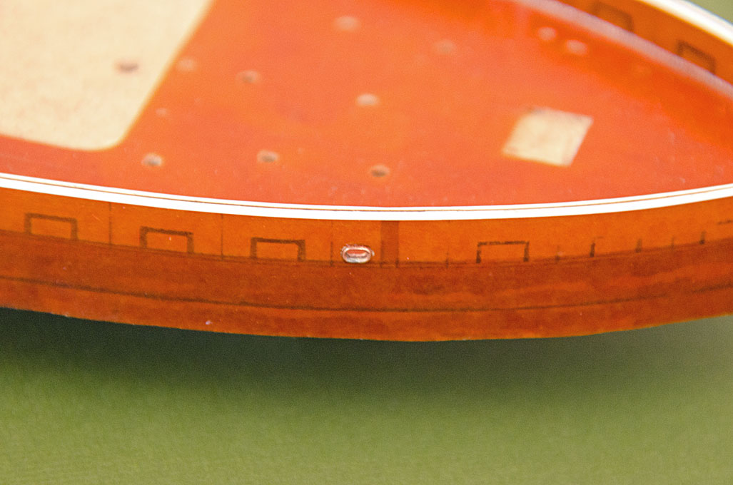
The lower carriage runs on four wheels that are guided by rails that have been turned on the lathe already a long time ago. These ‘castors’ are attached to the underside of the carriage by housings of sheet-metal that have no right angle in them and are set at an oblique angle to the carriage. These parts were developed from the various projections in the drawing above and then checked by printing them as large paper parts.
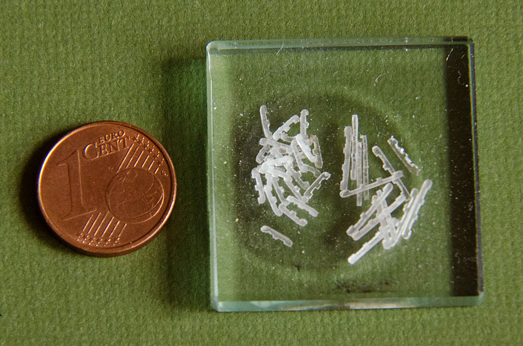
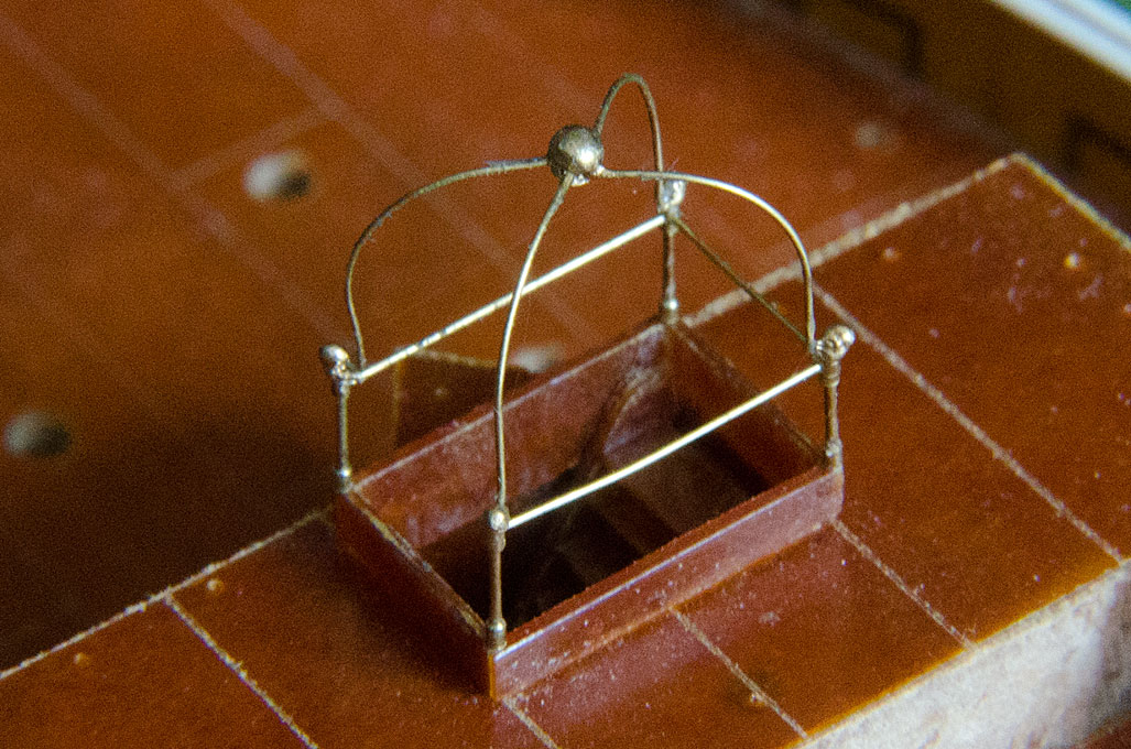
A lot of work were also the many operating platforms resting on consoles fabricated from L-profiles. Unfortunately, the exact shape and position of the consoles cannot de deducted from the above drawings for all of them. The model in Copenhagen and the originals in Suomenlinna have lower carriages that differ in detail. I will provide two alternatives for the grilles made from wire mesh on the etched fret. The more elaborate version will consist of etched and folded frames with inlays of a very fine steel wire-mesh. If it does not work to cut the wire-mesh to size – some of the platforms are onyl 1.6 mm wide – I will have solid platforms into which a mesh-like structure is etched as fall-back option.
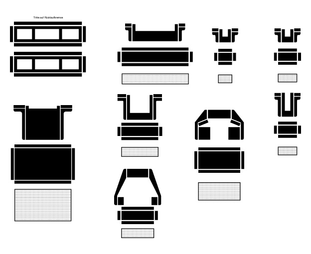 Elements (operating platforms) for etched fret
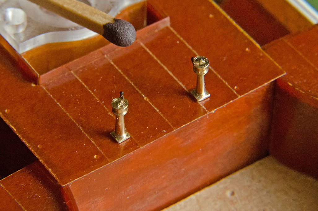
Also the charging-crane will be built up from several layers of etched part – to get the necessary thickness – and turned parts. The same approach was taken for several other small parts that would be difficult to machine or work on by hand due to their small size, while still requiring a precise geometry.
I still have to design a host of other parts that have to go onto the etched fret in order to make it worthwhile to be given outside for having the mask and the etching done professionally.
To be continued soon ...


