The Ship Model Forum

The Ship Modelers Source
It is currently Thu Apr 18, 2024 3:30 pm

All times are UTC - 6 hours [ DST ]


Post new topic Reply to topic  [ 483 posts ]  Go to page Previous  1, 2, 3, 4, 5, 6, 7, 8 ... 25  Next
Author Message
PostPosted: Mon Jul 08, 2019 6:50 pm 
Offline
User avatar

Joined: Sat Apr 29, 2006 7:36 am
Posts: 658
Location: Vigo, Spain
Hi again Larry and all,

Anyway, the buttoms have much more interest than this. For these to be perfect, you will have to heat only the very tip of the rod, and the buttom will come by itself. Then, while it is hot, press against a hard surface, and you will have wheels, handles or flat bases for whatever you may need. Or wait until it cools off completely, and sand gently. You will get the very same thing.
Attachment:
(305b).jpg
(305b).jpg [ 83.08 KiB | Viewed 2979 times ]

Attachment:
(306).JPG
(306).JPG [ 179.69 KiB | Viewed 2979 times ]

You can also have lamps :
Attachment:
(307).jpg
(307).jpg [ 180.27 KiB | Viewed 2979 times ]

Attachment:
(308).JPG
(308).JPG [ 138.8 KiB | Viewed 2979 times ]

All kind of handles and supports :
Attachment:
(309).JPG
(309).JPG [ 246.93 KiB | Viewed 2979 times ]

Attachment:
(310).JPG
(310).JPG [ 168.57 KiB | Viewed 2979 times ]

Whip aerials are simply pieces of stretched sprue with a buttom at the base, one single piece each:
Attachment:
(311).JPG
(311).JPG [ 182.87 KiB | Viewed 2979 times ]

I use this technique en masse, as these are the easiest pieces to produce, and when painted and completely finished, the results can be surprisingly good. Have a look at a OHP/Santa Maria class frigate, Lee 1/300 :
Attachment:
(312).JPG
(312).JPG [ 180.49 KiB | Viewed 2979 times ]

Attachment:
(313).JPG
(313).JPG [ 172.52 KiB | Viewed 2979 times ]

Attachment:
(314).JPG
(314).JPG [ 186.89 KiB | Viewed 2979 times ]

Actually much better than PE, because PE lacks volume.
I hope this has been of some help too, and again best regards from Spain,

Willie.

_________________
Amen dico tibi, hodie mecum eris in paradiso (Lk 23,43).


Last edited by Willie on Thu Oct 10, 2019 3:38 am, edited 1 time in total.

Report this post
Top
 Profile  
Reply with quote  
PostPosted: Wed Jul 10, 2019 10:41 am 
Offline
User avatar

Joined: Tue Aug 25, 2015 1:33 pm
Posts: 489
Location: Grand Rapids, Michigan
Good grief, Willie!! I didn't expect a detailed tutorial with pictures and everything! Wow! Thanks a million!

I printed this off and now I have to get some stock and try this. Looks like it may take a few tries to master it, but in all actuality, it doesn't look all that hard.

Thanks again, and I appreciate all the work you did to do this. This particular post should really be added to the "Tips and Tricks" forum.

_________________
Larry Steiner


Completed: 1:200 USS Missouri (Monster Mo)
Next project: Definitely NOT another big ship!!


Report this post
Top
 Profile  
Reply with quote  
PostPosted: Thu Jul 11, 2019 3:33 am 
Offline
User avatar

Joined: Sat Apr 29, 2006 7:36 am
Posts: 658
Location: Vigo, Spain
Hi there Larry and all,

My pleasure to know it was of some help.


steinerman wrote:
Looks like it may take a few tries to master it, but in all actuality, it doesn't look all that hard


At all, exactly. It should come in the "Easy tricks" chapter.

A further advance were the vents and grids under nº. 2 turret. I considered at first to build them also closed, but after the fact that they are bigger than the rest of them, and that in the hundreds of pictures that I seen they were always open, I considered that at least I could have a try. Not that they were a recurrent topic in my dreams, but I was thinking on how to make them for a long time.

This is what has to be made, port:


Attachment:
(315).jpg
(315).jpg [ 104.34 KiB | Viewed 2916 times ]


It can be observed that the lid opens sidewards. And here starboard:

Attachment:
(316).jpg
(316).jpg [ 90.29 KiB | Viewed 2916 times ]


The lid opens upwards.

So my solution was to make two grids out of PE pieces that I had around:


Attachment:
(317).jpg
(317).jpg [ 259.46 KiB | Viewed 2916 times ]


Then I made two frames with pieces of thin yogourth containers and 1,00 mm. Evergreen strip, using the very same grid as a pattern:

Attachment:
(318).jpg
(318).jpg [ 249.08 KiB | Viewed 2916 times ]


These pieces have a reinforcement inside, probably to avoid a sagging in the grid. These reinforcements are visible through the grid, and have to be present, something very easy to make as well with stretched sprue:

Attachment:
(319).jpg
(319).jpg [ 228.49 KiB | Viewed 2916 times ]


Attachment:
(320).jpg
(320).jpg [ 224.11 KiB | Viewed 2916 times ]


The background of the vents will be painted in black, and the reinforcements highlighted in light grey, so that they are apparent.
The lids were made using the same method, yogourth container and stretched sprue, but 0.75 Evergreen this time:


Attachment:
(321).jpg
(321).jpg [ 229.26 KiB | Viewed 2916 times ]


The final effect, even if dry fitted is excelent:

Attachment:
(322).jpg
(322).jpg [ 172.55 KiB | Viewed 2916 times ]


Attachment:
(323).jpg
(323).jpg [ 194.38 KiB | Viewed 2916 times ]


These pieces are again slightly over scaled, but not only I can live with this, but also that once painted the effect will improve.

I hope you like it, and very best regards,

Willie.

_________________
Amen dico tibi, hodie mecum eris in paradiso (Lk 23,43).


Report this post
Top
 Profile  
Reply with quote  
PostPosted: Thu Jul 11, 2019 5:29 am 
Offline
User avatar

Joined: Thu Mar 31, 2016 1:52 pm
Posts: 502
Location: Inverness
Very sharp, excellent modelling!

Cheers Jabb

_________________
HMS Hood, the big one!

I used to be indecisive, now I'm not so sure.


Report this post
Top
 Profile  
Reply with quote  
PostPosted: Thu Jul 11, 2019 9:32 pm 
Offline

Joined: Sat Jan 24, 2009 5:16 pm
Posts: 815
Location: Wisconsin
That is an excellent job on scratch building those parts!


Report this post
Top
 Profile  
Reply with quote  
PostPosted: Tue Jul 16, 2019 2:14 am 
Offline
User avatar

Joined: Sat Apr 29, 2006 7:36 am
Posts: 658
Location: Vigo, Spain
Hi Jabb, Joe Simon and all,

And thanks for your remarks.

The next element was the twin gun fire directors in both positions on the clip shack. For me, Fletchers were always closely connected with the Mk.51 fire director, of which there are hundreds of pictures and graphics in the net, this one :


Attachment:
(324).jpg
(324).jpg [ 85.54 KiB | Viewed 2831 times ]


On the other hand the offering of Revell seemed to me surprisingly inacurate, something that does not happen with many of other elements in the kit :

Attachment:
(326).jpg
(326).jpg [ 226.95 KiB | Viewed 2831 times ]


Building these little things, with so many loose ends, was tricky at times but again not difficult, and even reduced to the essential elements, the outcome is convincing :

Attachment:
(327).jpg
(327).jpg [ 199.8 KiB | Viewed 2831 times ]


But once finished, it came to my mind that these Mk.51 directors were usually associated with the 40.0 mm. Bofors, while USS McGowan and Jorge Juan were upgraded to 76.0 mm. guns, what meant that to be associated to the Mk.51 would be for these guns weird, to say the least.

A further research brought evidence: Jorge Juan had Mk.63 directors, not Mk.51, as it can be seen in two clear pictures of Jorge Juan herself, something I had not realized before :Mad_6: :bash_2: :


Attachment:
(328).jpg
(328).jpg [ 79.01 KiB | Viewed 2831 times ]


Attachment:
(329).jpg
(329).jpg [ 70.14 KiB | Viewed 2831 times ]


The offer of Revell seemed now much more logical, of course. I thought at first to ignore the fact and let the mistake go by, but this door was soon closed too: not only these two Mk.63 directors are far different from Mk.51´s, but are also much higher and positioned in very visible places, so they cannot be ignored even in an true good will exercise. Here on board Velox, in Faliro Port, Athens, with the breathtaking mount Licabethos in the background :

Attachment:
(330).JPG
(330).JPG [ 71.94 KiB | Viewed 2831 times ]


These Mk.63 directors are not described in both Al Ross´s AOTS The Sullivans and Alan Raven´s Fletcher-Class Destroyers books, and it is not that easy to find clear sketches or graphics of them, but at least I could find one that was clear enough :


Attachment:
(332).jpg
(332).jpg [ 38.07 KiB | Viewed 2831 times ]


To build these things was not difficult either, the only problem being to make straight bases, what can be solved with the mirror trick explained in one of the posts before. Here you are the basic elements, made with Evergreen rod and tube, and plastic yogourth containers:

Attachment:
(333).jpg
(333).jpg [ 186.04 KiB | Viewed 2831 times ]


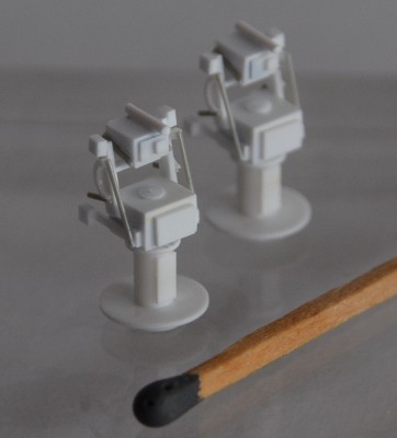
The final product, even if again reduced to minimums, seems to me quite acceptable :

Attachment:
(334).jpg
(334).jpg [ 196.54 KiB | Viewed 2831 times ]


Attachment:
(335).jpg
(335).jpg [ 249.29 KiB | Viewed 2831 times ]


I hope you like them, and warmest regards from this side,

Willie.

_________________
Amen dico tibi, hodie mecum eris in paradiso (Lk 23,43).


Report this post
Top
 Profile  
Reply with quote  
PostPosted: Tue Jul 16, 2019 2:20 am 
Offline
User avatar

Joined: Sat Apr 29, 2006 7:36 am
Posts: 658
Location: Vigo, Spain
A quick comparison with Revell´s offering, which is not bad and could be modified and used if a time saving was desired, allows to see the difference :

Attachment:
(336).jpg
(336).jpg [ 214.44 KiB | Viewed 2831 times ]


One set in place, IMO, the effect is excellent :

Attachment:
(337).jpg
(337).jpg [ 232.49 KiB | Viewed 2831 times ]


Again best regards from the North Atlantic,

Willie.

_________________
Amen dico tibi, hodie mecum eris in paradiso (Lk 23,43).


Report this post
Top
 Profile  
Reply with quote  
PostPosted: Tue Jul 16, 2019 12:25 pm 
Offline

Joined: Thu May 29, 2008 8:02 pm
Posts: 3825
Willie,

The Mk 63 Gun Fire Control System (GFCS) was a system of several components that were upgraded several times during its service career. The Mk 63 "director" was only one part and actually was an upgraded mod version of the Mk 51 (Mod 6) director with the Mk 15 gunsight in place of the Mk 14 gunsight used on earlier Mk 51 directors. The Mk 15 gunsight was eventually replaced with the Mk 29 gunsight (likely was used with all the 3-in guns equipped ships) and the pedestal was changed as well. The rest of the system included the mount installed radar (Mk 34 for the 3-in guns) antenna and the computer and radar electronics (in the deckhouse below the "directors"). The Mk 63 GFCS was introduced in 1945 for use on twin and quad 40-mm mounts, using the earlier Mk 28 radar.

The Mk 63 GFCS was declared obsolete (the system was never really effective against jet targets) in 1968 on USN ships and removed from most FLETCHER's still in USN service. Control of the 3-in guns was then done by the other directors onboard (FLETCHER's the Mk 37 and Mk 56 directors) as had been wired in from the start.


Report this post
Top
 Profile  
Reply with quote  
PostPosted: Wed Jul 17, 2019 5:00 am 
Offline
User avatar

Joined: Sat Apr 29, 2006 7:36 am
Posts: 658
Location: Vigo, Spain
Hi there Mr. Davis and all,

Thanks for the additional info. Again an excellent explanation from an (clearly) expert.


Rick E Davis wrote:
The Mk 63 Gun Fire Control System (GFCS) was a system of several components that were upgraded several times during its service career. The Mk 63 "director" was only one part (...) The rest of the system included the mount installed radar (Mk 34 for the 3-in guns) antenna and the computer and radar electronics (in the deckhouse below the "directors")


Actually I had found a complete graphic of everything you explain. Your notes settle the subject forever.


Attachment:
(338).jpg
(338).jpg [ 131.18 KiB | Viewed 2787 times ]


Best regards from this side,

Willie.

_________________
Amen dico tibi, hodie mecum eris in paradiso (Lk 23,43).


Report this post
Top
 Profile  
Reply with quote  
PostPosted: Wed Jul 17, 2019 6:34 am 
Offline
User avatar

Joined: Sun May 20, 2012 6:01 am
Posts: 409
Location: Ontario Canada
Super work,Willie!

Scott

_________________
K494 HMCS Arnprior
Royal Canadian Navy


Report this post
Top
 Profile  
Reply with quote  
PostPosted: Sat Jul 20, 2019 11:44 am 
Offline
User avatar

Joined: Sat Apr 29, 2006 7:36 am
Posts: 658
Location: Vigo, Spain
Hi there Folks,

And thanks Scott for your remark.

The new advances are a side effect of my last failure with the Mk.51-Mk.63, because as I was looking for pics of the Mk.63 I came across some excellent pics of the radar mounted on two of the guns, something that I had never found before. These ones :


Attachment:
(339).JPG
(339).JPG [ 70.3 KiB | Viewed 2738 times ]

Attachment:
(340).JPG
(340).JPG [ 53.42 KiB | Viewed 2738 times ]

Attachment:
(341).jpg
(341).jpg [ 20.35 KiB | Viewed 2738 times ]


The pieces of the basic structure were made with Evergreen and very thin yogourth container, a bit thinner than the 0.25 mm. Evergreen. :

Attachment:
(342).jpg
(342).jpg [ 216.77 KiB | Viewed 2738 times ]


The two round aerials were not that easy to make until I discovered that I had actually ca. a dozen in my hands, as I could use the mines that the Revell kit offers for the German Fletchers that had mining capabilities as, the same as in the case of all German destroyers in WWII, they were refitted with mine rails on the aft deck. These are the mine halves :

Attachment:
(343).jpg
(343).jpg [ 251.64 KiB | Viewed 2738 times ]


After I had found these pieces, the aerials themselves were a matter of some (well, many) minutes of work, but not difficult at all :

Attachment:
(344).jpg
(344).jpg [ 243.93 KiB | Viewed 2738 times ]


The yokes where the aerials are to be set were made with Evergreen tubing, refined with side cuts and completed with pieces of plastic scrap and stretched sprue :

Attachment:
(345).jpg
(345).jpg [ 252.99 KiB | Viewed 2738 times ]

Attachment:
(346).jpg
(346).jpg [ 237.52 KiB | Viewed 2738 times ]


As I was making time for the yokes to dry completely I finished the aerials, again with Evergreen tubing and stretched sprue.

Attachment:
(347).jpg
(347).jpg [ 233.9 KiB | Viewed 2738 times ]


Evergreen tubing will never be blessed enough, because the fact that they are telescopic to each other opens a full range of possibilities with no work at all.

Over the the next post.

Willie.

_________________
Amen dico tibi, hodie mecum eris in paradiso (Lk 23,43).


Report this post
Top
 Profile  
Reply with quote  
PostPosted: Sat Jul 20, 2019 12:12 pm 
Offline
User avatar

Joined: Sat Apr 29, 2006 7:36 am
Posts: 658
Location: Vigo, Spain
And hi again :

Another thing I discovered (and that probably saved me from another hour of cursing in the future) is that these two aerials were not installed in the same place even in the Spanish Fletchers. This is Jorge Juan :


Attachment:
(348).jpg
(348).jpg [ 119.9 KiB | Viewed 2737 times ]


But this is Alcalá Galiano, her sister ship, both "31" on the elevating mechanism allowing to see that the pictures are not simply inverted :

Attachment:
(349).jpg
(349).jpg [ 39.89 KiB | Viewed 2737 times ]


The final product is this :

Attachment:
(350).jpg
(350).jpg [ 216.42 KiB | Viewed 2737 times ]

Attachment:
(351).jpg
(351).jpg [ 213.88 KiB | Viewed 2737 times ]

Attachment:
(352).jpg
(352).jpg [ 213.09 KiB | Viewed 2737 times ]

Attachment:
(353).jpg
(353).jpg [ 220.33 KiB | Viewed 2737 times ]


I hope you like them, and best summer regards from the North Atlantic,

Willie.

_________________
Amen dico tibi, hodie mecum eris in paradiso (Lk 23,43).


Report this post
Top
 Profile  
Reply with quote  
PostPosted: Tue Jul 23, 2019 1:44 am 
Offline
User avatar

Joined: Mon Jul 01, 2013 6:55 am
Posts: 421
Location: Madrid (Spain)
Amazing work Willie.

Jorge

_________________
Currently working on:

USS Nimitz 1/200
http://www.shipmodels.info/mws_forum/viewtopic.php?f=13&t=153310


Report this post
Top
 Profile  
Reply with quote  
PostPosted: Tue Jul 23, 2019 5:29 am 
Offline
User avatar

Joined: Mon Nov 04, 2013 2:17 am
Posts: 283
Location: _/\/¯¯¯¯¯\/\_ Cape Town
Great work, love your detail!!


Report this post
Top
 Profile  
Reply with quote  
PostPosted: Tue Oct 08, 2019 5:01 pm 
Offline
User avatar

Joined: Sat Apr 29, 2006 7:36 am
Posts: 658
Location: Vigo, Spain
Hi all again,

After Photobucket has ruined my threads forever watermarking them first and blurring them afterwards, and some modelers have written privately to me asking for some of the pictures, I have taken the time to convert this thread to the standard right-click pictures of the forum. This way they will always be available.

When I have the ocassion I will try to do the same with my other two threads, HMS Campbeltown and SNS Santa María, and also with my contributions to the threads of other modelers. it is very easy, but time consuming.

Never ever will I use Photobucket, Tinypics or whatever again. Bunch of pirates.

Best regards from the North Atlantic,

Willie.

_________________
Amen dico tibi, hodie mecum eris in paradiso (Lk 23,43).


Report this post
Top
 Profile  
Reply with quote  
PostPosted: Wed Oct 09, 2019 4:56 pm 
Offline
User avatar

Joined: Mon Jan 10, 2005 5:30 pm
Posts: 5386
Location: Nr Southampton England
Most excellent work Willie!--

much dedication and tenacity in observation of photos...
and neatly translated to intense detail on your model!

I fully echo your sentiments about the on-line Pirates , photobucket et al

Bravo!

JIM BAUMANN

_________________
....I buy them at three times the speed I build 'em.... will I live long enough to empty my stash...?
http://www.modelshipgallery.com/gallery ... index.html

IPMS UK SIG (special interest group) www.finewaterline.com


Report this post
Top
 Profile  
Reply with quote  
PostPosted: Mon Feb 17, 2020 5:58 pm 
Offline
User avatar

Joined: Sat Apr 29, 2006 7:36 am
Posts: 658
Location: Vigo, Spain
Hi all again, folks,

After so much time, I have at last the opportunity for a quick update of my Jorge Juan.

The problem this time was the clip shack between the stacks. Not the clip shack itself, but the stanchions and the handrails, which have a very distinctive shape. My USS The Sullivans files are complete, but of no complete help this time, but I have been able to find two pics of the same area on board Jorge Juan.

This is what I mean, fore :
Attachment:
(354).jpg
(354).jpg [ 134.61 KiB | Viewed 1132 times ]

And aft :
Attachment:
(355).jpg
(355).jpg [ 141.42 KiB | Viewed 1132 times ]

After much hesitation, as the lines are really complicated and as there is no PE for this element at all (this time I would have gone for one), I tried with Evergreen. First the stanchions, with 0.64 mm. rod, and then the handrails, 0.50 mm. rod. I tried combing the 0.50 rod at first, but to combine length and curves with the precision that this needs was beyond my ability, so I had to try sections:
Attachment:
(356).jpg
(356).jpg [ 272.57 KiB | Viewed 1132 times ]

The only (!!!) problem with this solution is that the segments have to be absolutely parallel if the effect is to be convincing:
Attachment:
(357).jpg
(357).jpg [ 153.34 KiB | Viewed 1073 times ]

After this I had to fix the rest of the elements, that have to be absolutely precise if you don´t want to see all the rest of the sections around combed and twisted, ruining the overall effect. Precision means this time that the sections have to stand by themselves when dry fitted, by simple pressure, but without distorting the elements that support them. Easier to say than to do, but more or less I think I got it:
Attachment:
(358).jpg
(358).jpg [ 257.93 KiB | Viewed 1132 times ]

Attachment:
(359).jpg
(359).jpg [ 249.52 KiB | Viewed 1132 times ]

The sections aft were way easier to build, again 0.64 and 0.50 mm. Evergreen rod:
Attachment:
(360).jpg
(360).jpg [ 239.49 KiB | Viewed 1132 times ]

And with all the elements already built present, the clip shack is at the moment like this :
Attachment:
(361).jpg
(361).jpg [ 259.69 KiB | Viewed 1132 times ]

Attachment:
(362).jpg
(362).jpg [ 271.52 KiB | Viewed 1132 times ]

Attachment:
(363).jpg
(363).jpg [ 273.89 KiB | Viewed 1132 times ]

So I hope you like it, and very best and warmest regards from this side,

Willie.

_________________
Amen dico tibi, hodie mecum eris in paradiso (Lk 23,43).


Last edited by Willie on Tue Feb 18, 2020 12:21 pm, edited 1 time in total.

Report this post
Top
 Profile  
Reply with quote  
PostPosted: Tue Feb 18, 2020 6:35 am 
Offline

Joined: Thu Jan 26, 2017 8:30 am
Posts: 202
incredible what you are doing. Just read the parts I've missed so far. Nice tip about the checking of the parts: simple, but effective.

Also a thumbs up (again) for the excellent piece of scratchbuilding you are doing here...


Report this post
Top
 Profile  
Reply with quote  
PostPosted: Mon Mar 16, 2020 11:30 am 
Offline
User avatar

Joined: Sat Apr 29, 2006 7:36 am
Posts: 658
Location: Vigo, Spain
Hi there folks,

And thanks a lot Silenoz, for your very kind remarks.

I am always thinking on how to make the oil canning effect on the hull, and planning the wiring in the aft stack. Reviewing some pics in my files, I realized that I had made a mistake when making platform for the torpedo director, and that is that I had ignored the trunk for the wiring underneath, through which all the wires come to the director itself.

That is again a problem, because I have only one picture of this platform on board Jorge Juan, and it is of virtually of no help, this one:

Attachment:
(364).jpg
(364).jpg [ 157.77 KiB | Viewed 925 times ]

I have two pics of different units, this one, of USS Cassing Young:
Attachment:
(365).jpg
(365).jpg [ 69.47 KiB | Viewed 925 times ]

And this other one of Velox:
Attachment:
(366).JPG
(366).JPG [ 85.33 KiB | Viewed 925 times ]

Both ships seem to have different ways of attaching the wiring to the director. In the doubt, I chose the one of Velox, because this thick piece of tubing will allow to make the wiring disappear inside the director much more easily. This was then my solution :
Attachment:
(367).jpg
(367).jpg [ 239.19 KiB | Viewed 925 times ]

While doing this, I came across this picture, the dust cover of a book dealing with Z1, one of the Bundesmarine´s Fletchers, very interesting because it shows the inside of the bulkheads around the a/a battery:
Attachment:
(368).jpg
(368).jpg [ 146.9 KiB | Viewed 925 times ]

After this I made the boxes, that were most surely for telephones and small stuff. I presume that both bulkheads were simetrical in their gear, although they were of different length:
Attachment:
(369).jpg
(369).jpg [ 221.79 KiB | Viewed 925 times ]

Attachment:
(370).jpg
(370).jpg [ 224.45 KiB | Viewed 925 times ]

As you can see, the macro has no mercy, even for its closest friends !!! When painted, with a wash in greys and some dry brush it will look much better.

Best regards from this side,

Willie.

_________________
Amen dico tibi, hodie mecum eris in paradiso (Lk 23,43).


Report this post
Top
 Profile  
Reply with quote  
PostPosted: Thu Mar 19, 2020 7:51 pm 
Offline
User avatar

Joined: Sat Apr 29, 2006 7:36 am
Posts: 658
Location: Vigo, Spain
Hi again to all modelers,

Today´s work was adding some detail to the aft structure, at the level of main deck. Of this area I have again very little information of Jorge Juan, only two general pictures on both sides of the ship, these one showing some useful detail:
Attachment:
(371).jpg
(371).jpg [ 46.54 KiB | Viewed 833 times ]

And this one of the other side, much less useful:
Attachment:
(372).jpg
(372).jpg [ 107.07 KiB | Viewed 833 times ]

Other than this, only one that under the circumstances can be considered a true close up:
Attachment:
(373).jpg
(373).jpg [ 103.93 KiB | Viewed 833 times ]

For the starboard bulkhead, I used then these two pics of USS The Sullivans:
Attachment:
(374).JPG
(374).JPG [ 165.23 KiB | Viewed 833 times ]

Attachment:
(375).JPG
(375).JPG [ 165.47 KiB | Viewed 833 times ]

The most tricky thing was to make a set of what seems to be pump exhausts, fixed to the main deck. The process is easy, carving a rod with triangular, square and round files, refining with an X-acto blade and fine sandpaper completing with other pieces of styrene:
Attachment:
(376).jpg
(376).jpg [ 338.23 KiB | Viewed 833 times ]

Attachment:
(377).jpg
(377).jpg [ 359.94 KiB | Viewed 833 times ]

So are the details of the starboard bulkhead now:
Attachment:
(378).jpg
(378).jpg [ 184.22 KiB | Viewed 833 times ]

Attachment:
(379).jpg
(379).jpg [ 267.31 KiB | Viewed 833 times ]

Curving styrene rod for the pipes is always unpleasant, to put it mildly, but I think that more or less I got it.

_________________
Amen dico tibi, hodie mecum eris in paradiso (Lk 23,43).


Report this post
Top
 Profile  
Reply with quote  
Display posts from previous:  Sort by  
Post new topic Reply to topic  [ 483 posts ]  Go to page Previous  1, 2, 3, 4, 5, 6, 7, 8 ... 25  Next

All times are UTC - 6 hours [ DST ]


Who is online

Users browsing this forum: Sszabi, wefalck and 39 guests


You can post new topics in this forum
You can reply to topics in this forum
You cannot edit your posts in this forum
You cannot delete your posts in this forum
You cannot post attachments in this forum

Jump to:  
Powered by phpBB® Forum Software © phpBB Group