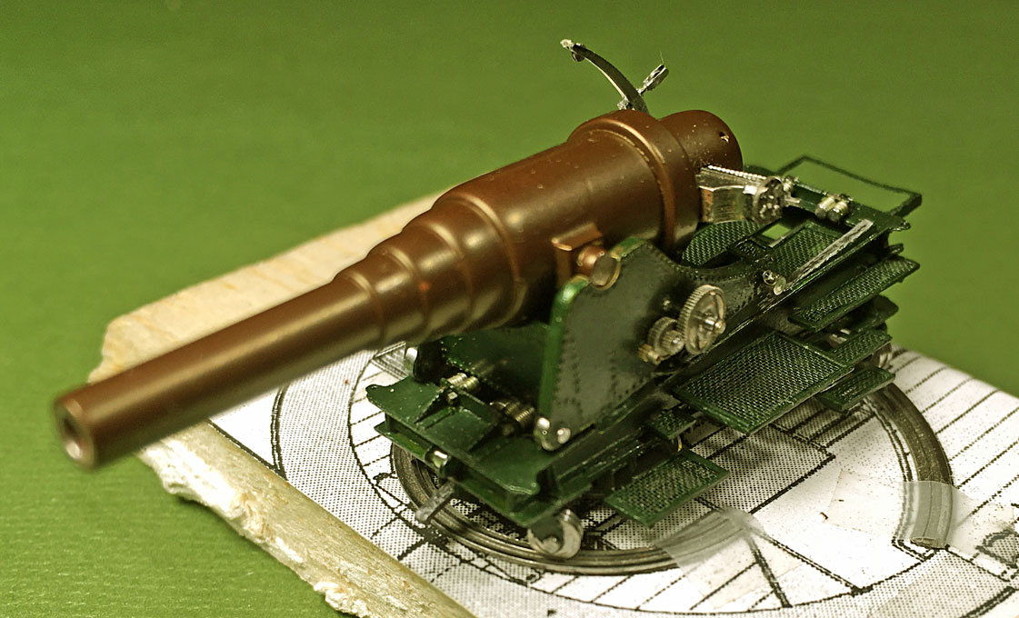
The Ship Model Forum

The Ship Modelers Source
It is currently Tue Apr 16, 2024 12:13 am

All times are UTC - 6 hours [ DST ]


Post new topic Reply to topic  [ 384 posts ]  Go to page Previous  1 ... 4, 5, 6, 7, 8, 9, 10 ... 20  Next
Author Message
PostPosted: Wed Aug 26, 2020 9:59 am 
Offline
User avatar

Joined: Wed Sep 28, 2011 12:04 pm
Posts: 1815
Location: Paris
Thanks for the kind words !

I had linked the pictures through https, but my certificate expired and I have not been able to renew it yet. I changed the links to http and it should work again now.

_________________
Eberhard

Former chairman Arbeitskreis historischer Schiffbau e.V. (German Association for Shipbuilding History)

--------------------------------------------------------------------------------------------------------------------------------------------------------------------------------------------

Image Image Image Image


Report this post
Top
 Profile  
Reply with quote  
PostPosted: Wed Aug 26, 2020 4:58 pm 
Offline
User avatar

Joined: Mon Jan 10, 2005 5:30 pm
Posts: 5385
Location: Nr Southampton England
Wefalck wrote:

>>> .... It continues to frustrate how little I have to show for a few hours of toiling in the workshop,...<<<

ACTUALLY.... I disagree! :cool_1:

The close up images of the elevating mechanism reflect EXACTLY the extreme time spent;

This work is SUPERLATIVE--- and no amount of ' shortcut ' PE would ever achieve this feeling of
solidity in this relatively large scale.

a hearty bravo!

JIM B :thumbs_up_1: :thumbs_up_1:

_________________
....I buy them at three times the speed I build 'em.... will I live long enough to empty my stash...?
http://www.modelshipgallery.com/gallery ... index.html

IPMS UK SIG (special interest group) www.finewaterline.com


Report this post
Top
 Profile  
Reply with quote  
PostPosted: Thu Aug 27, 2020 3:35 am 
Offline
User avatar

Joined: Wed Sep 28, 2011 12:04 pm
Posts: 1815
Location: Paris
Thanks, Jim. This exactly has been always my concern: to give the parts their scale thickness and 3D shape. Etching is a very useful process, but in many cases etched parts as such are just too thin or too flat. There is an appropriate manufacturing technique for each part.

_________________
Eberhard

Former chairman Arbeitskreis historischer Schiffbau e.V. (German Association for Shipbuilding History)

--------------------------------------------------------------------------------------------------------------------------------------------------------------------------------------------

Image Image Image Image


Report this post
Top
 Profile  
Reply with quote  
PostPosted: Thu Aug 27, 2020 12:44 pm 
Offline
User avatar

Joined: Wed Sep 28, 2011 12:04 pm
Posts: 1815
Location: Paris
Completing the upper carriage 3

Progress in homeopathic doses: I realised that I forgot the the two steps at the end of the upper carriage. So, the parts for the frame were laser-cut, pieces of tea-bag mesh inserted and the assembly attached to the carriage with lacquer.

Image
Steps for the gun-layer

I realised now that I had assembled so many tiny parts for the gun, that it became difficult to not loose them and to remember what they were for. Some of the parts indeed had been made years ago. Therefore, I will proceed now to paint the parts and to assemble the gun, which then will be placed as a whole into the barbette, once the model is getting close to be finished.


Preparations for painting

While the paint scheme overall is quite clear, as it had been laid down in an ordinance of 1874, a few details have caused and still do cause some head-scratching. One of them is the exact hue of the ‘yellow’ for the funnel and the two boiler-room ventilators.

Unfortunately, no colour recipes seem to have survived, if there had been any. I undertook some research by proxy, reviewing what other navies at the same time might have done. The paint scheme of the French navy of that time is very different, but that of the Royal Navy is quite similar (or perhaps the other way around). For instance, HMS GANNET, preserved and restored in Chatham, is from the same period. Due to the Corona-crisis the reponse from Chatham to an enquiry is still incomplete. I wanted to know what paint was used in her restoration. Looking through artistic representations of the time, one has the feeling that the yellow was paler and more like buff, than the one used later by the Imperial German Navy.

It is notoriously difficult to judge hues on computer screens and on printed colour cards. To begin with, I selected a range of possible colours from my stock and also went through the colour cards of Schmincke, Vallejo, and Prince August (the French trade name for Vallejo). These candidates I tried out on pieces of the material to painted.

Image
Colour samples

The hull will be black outside and white inside, the deckhouse and the inside of the barbette will be also white. The decks, where not wood, will be a dark grey, as they had been painted in tar with sand mixed in to make them less slippery.
The gun carriage will be painted green, as evidenced by some contemporary builders’ models and a somewhat later instruction manual. The hue of the green is another issue. It was probably based on chrome oxide green.

The barrel of these breech-loading guns was scraped clean, then wiped with vinegar until a brownish oxide layer developed. The process was repeated several times and any loose ‘rust’ wiped off. Finally, the barrel was rub down with lineseed oil, effectively producing in situ a paint with ferric oxihyroxide and ferric acetate as pigment. The resulting colour would be something like caput mortuum. This is the way the barrel of the demonstration model in Copenhagen seems to have been treated. Moving parts and mechanically relevant surfaces were keept clean carefully, of course. I will, therefore, lightly spray the barrel in Schmincke caput mortuum.

To be continued ...

_________________
Eberhard

Former chairman Arbeitskreis historischer Schiffbau e.V. (German Association for Shipbuilding History)

--------------------------------------------------------------------------------------------------------------------------------------------------------------------------------------------

Image Image Image Image


Report this post
Top
 Profile  
Reply with quote  
PostPosted: Sun Sep 27, 2020 3:15 pm 
Offline
User avatar

Joined: Wed Sep 28, 2011 12:04 pm
Posts: 1815
Location: Paris
Assembly of the gun

Slow progress with steps forward and backward ... and a lot of sweat and bad language ... :woo_hoo:

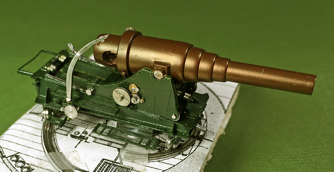
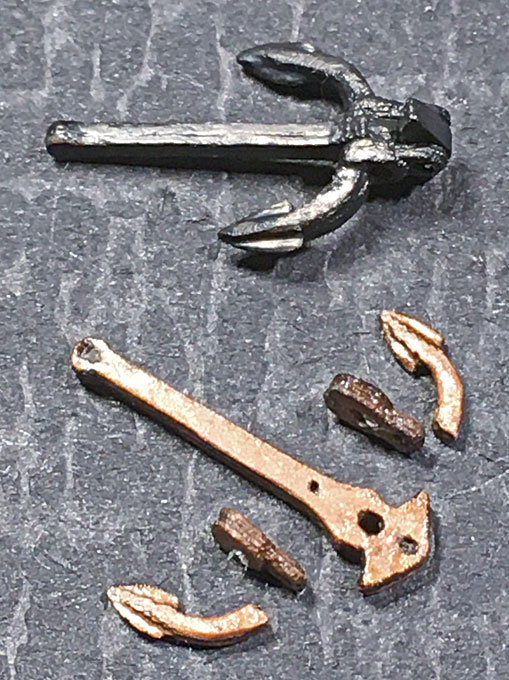
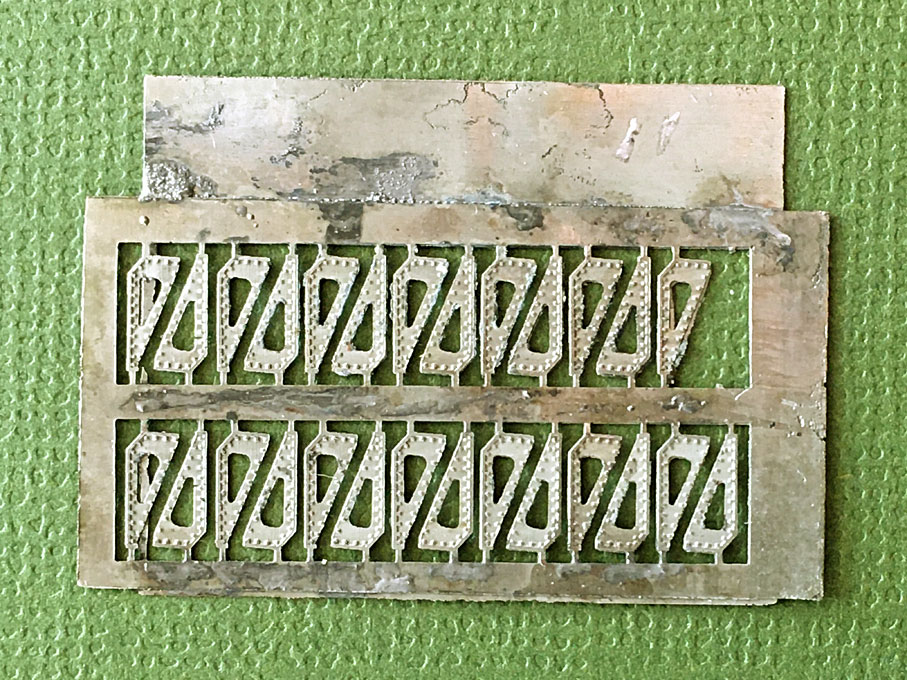
All parts temporarily assembled had to be taken apart for painting first. After selecting a green for the carriage, all the parts were given several light coats with the airbrush until a uniform colour and sheen was achieved. Not so easy on some of the complex parts. After letting it thoroughly dry, the paint was scraped off from those parts that are meant to be bare metal, but could not be masked off, due to being difficult to access.

Image

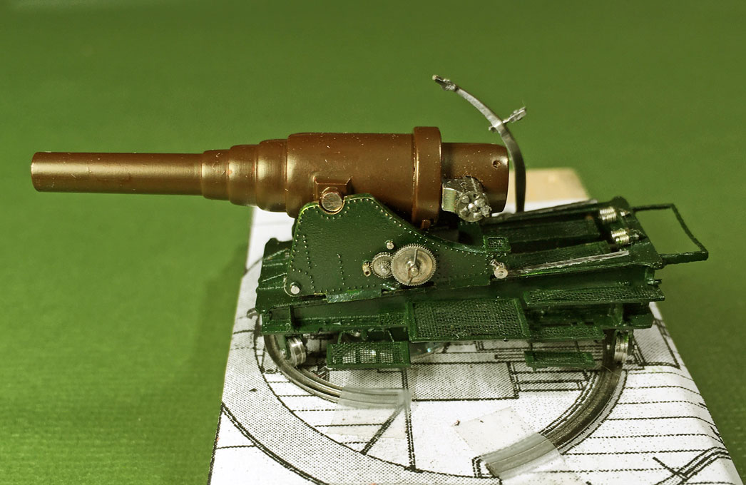
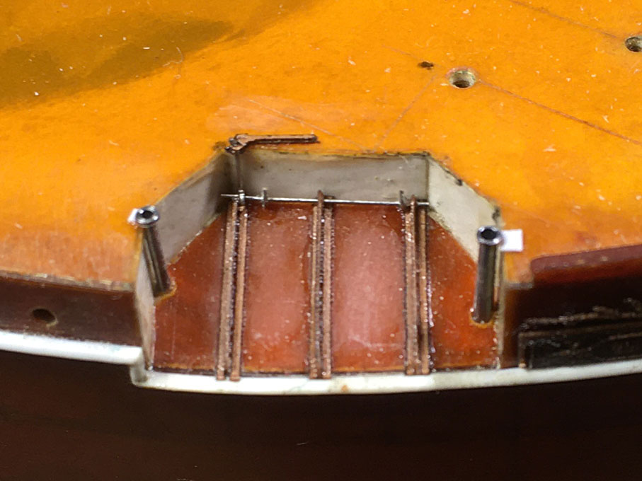
The assembly then proceeded from the inside out on the lower carriage. First the parts for the hydraulic recoil brake were installed. I decided to deviate from the prototype and not to install the protective tunnel over the piston of the brake in order to show the metal-work. I think this small bit of artistic license is permissible. All parts were put together with small blobs of zapon-lacquer, which dries up quite invisible.
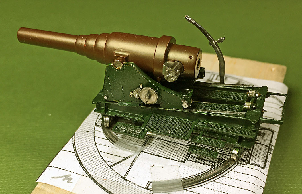
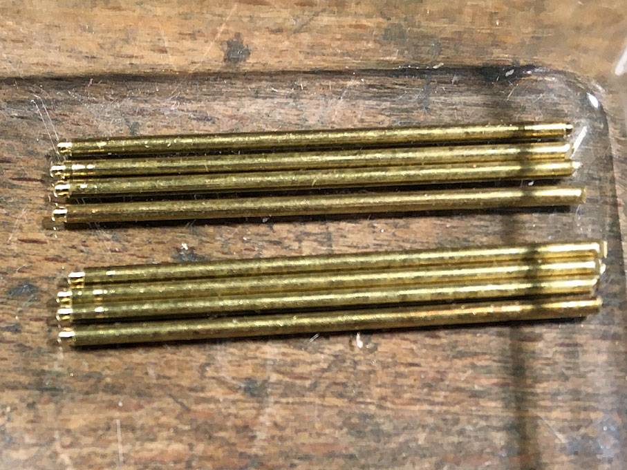
Next the spring buffers were installed. Putting in the tiny hexagonal nuts required a very deep breath each time.

Image

Flipping the carriage over the caster-wheels were put back, but this really taxed my patience. The wheels are held in place by little flat-head pins inserted from both sides. A simple through-pin would have been easier to install, but wouldn’t be quite prototype fashion.
The lower-carriage was very difficult to handle due to the flimsy and delicate grilles and steps. One was broken off in the process, but luckily attached nicely again.

Image

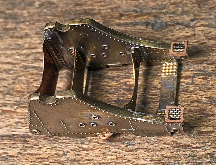
The rail on which the upper carriage runs would be bare metal. Here the limitations of using cardboard as structural element shows its limitations. If I had used etched brass parts, I would have chemically tinned them before assembly and now could have just scraped off the paint or masked the area before painting to reveal the metal. Now I had to simulate it with paint and a soft lead pencil. I am not entirely satisfied with the result, but can’t do anything about it now anymore.
Overall, I am somewhat ambivalent as to the merit of using cardboard. The surface and cut edges simply are not as smooth as those of metal or plastics, such as bakelite paper or styrene. Unfortunately, styrene could not be cut with my small laser-cutter.

Image

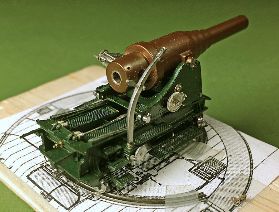
When proceeding to the upper carriage, I noticed a couple of mistakes I made years ago, when putting it together. Two of the transversal members were installed at a wrong place. The wheels of the carriage would have not touched the rails otherwise. When trying to rectify this, the whole assembly gave, but luckily I managed to put it back together without permanent damage.

Image

Another issue also arose: one should not work from drawings alone, particularly in a project that streches so long as this one. It turned out that the carriage was a couple of tenths of milimeters to narrow and would not fit over the lower carriage with its guiding plates. I should have properly verified this, when developing the parts for the lower carriage. With a bit of bending and tweaking it could be made to fit, but cobble-jobs like this leave parts behind that are not as crisp as they should be.

Image

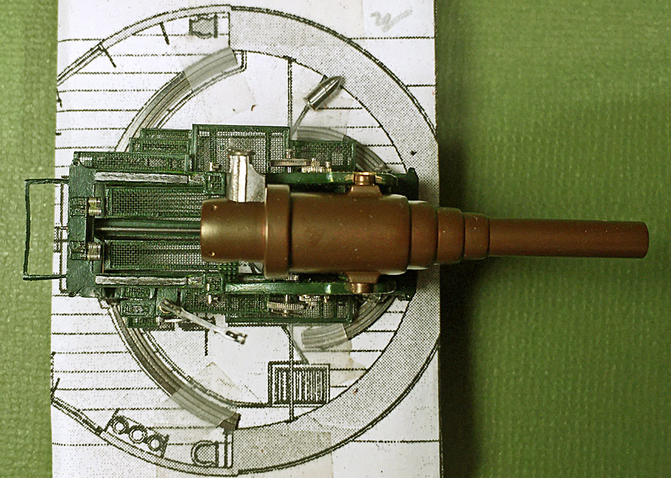
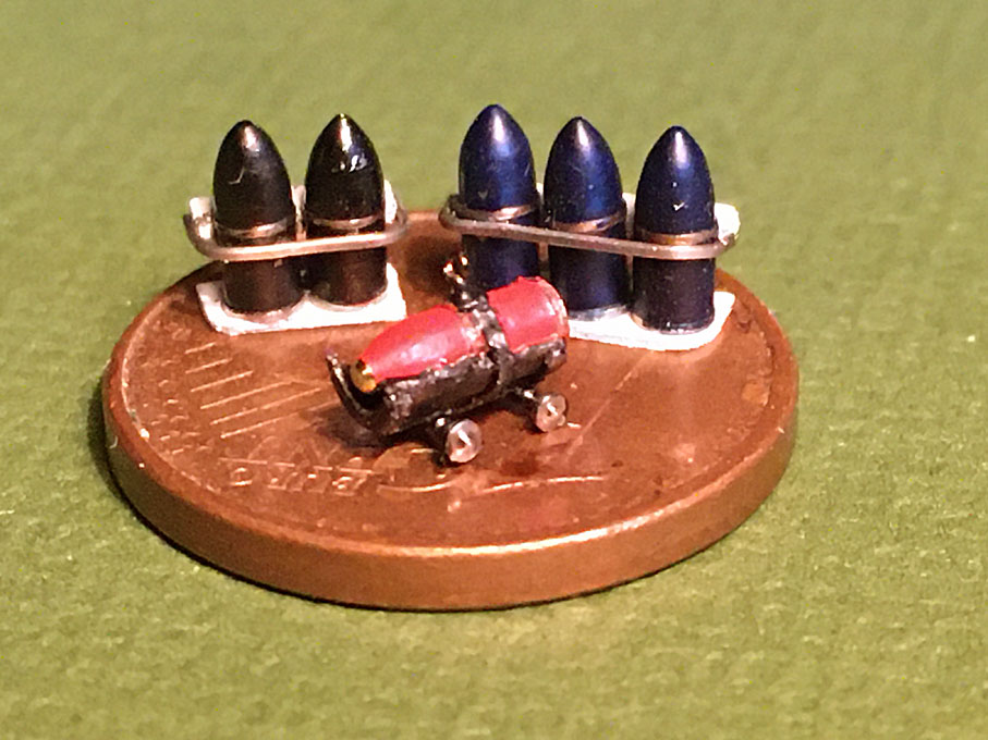
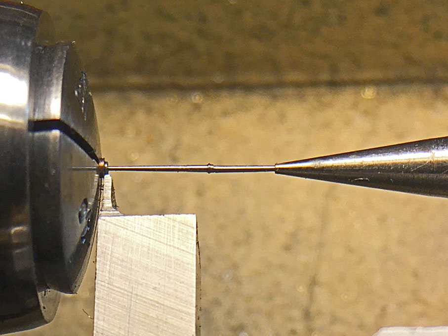
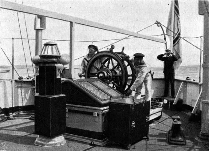
Painting the gun barrel turned out to be a major nightmare. I did not want to prime the steel in order to not loose its metallic appearance. Usually, acrylic paints dry so fast that there are not serious issues with rust formation. When I first applied the first coat it looked ok, but the next morning it had developed a mottled appearance. The same phenomenon reappeared after each coat, but somewhat less. I attributed it to the fact that the bottle of paint was actually almost 25 years old and it had not been sufficiently mixed. In the end I cleaned off the paint and began again, but with the same result. Once more I took the paint off and then sprayed it, but without agitating the bottle, thinking that some of the pigment might have coagulated – same result. Finally, I decided to lightly prime the barrel with zapon-lacquer to isolate the steel. This forms a very thin and virtually invisible layer. This did the trick, but the priming was not done carefully enough and some spots were left bare – with the result that those areas appeared mottled again. I tried dipping, but this leaves a too thick layers in corners etc. Eventually, I managed to obtain a reaonably even layer – one has to work very fast and going over areas already treated is virtually impossible due to the rapid drying. It is also very difficult see, whether one has covered the whole surface. In conclusion, I think the pigment of caput mortuum, which probably is the mineral haematite (Fe3O4) has reacted with the steel (Fe0) leading to the mottled appearance. However, I managed to reproduce the appearance of the barrel of the demonstration model in Copenhagen reasonably well, considering the small scale.

Image

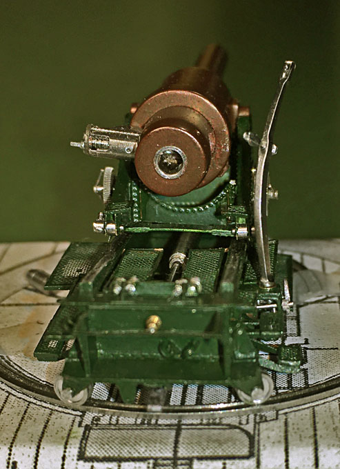
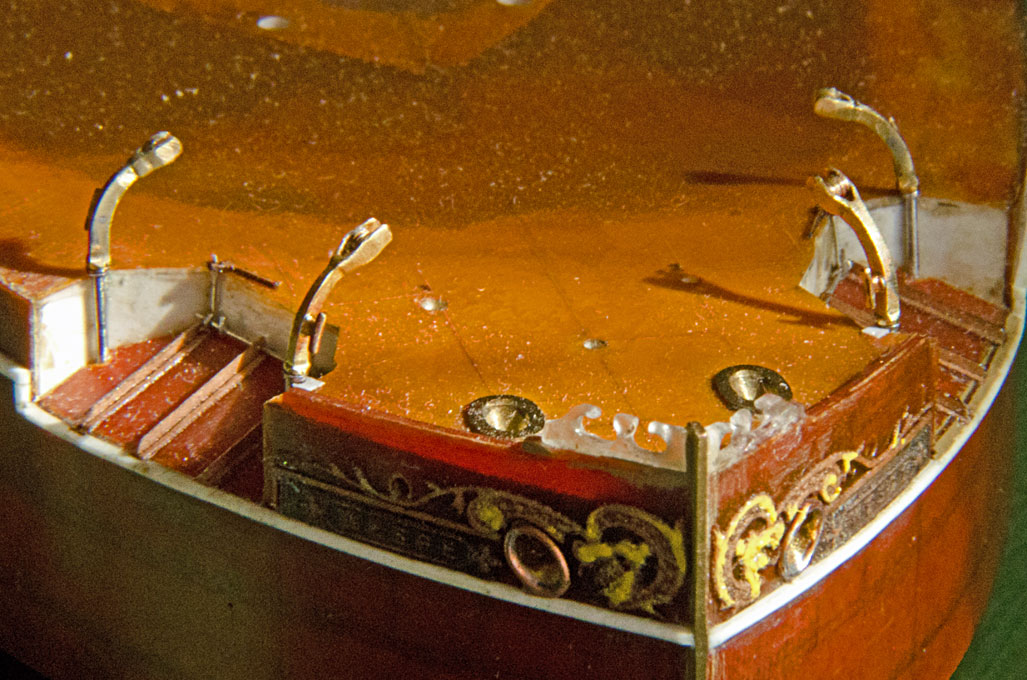
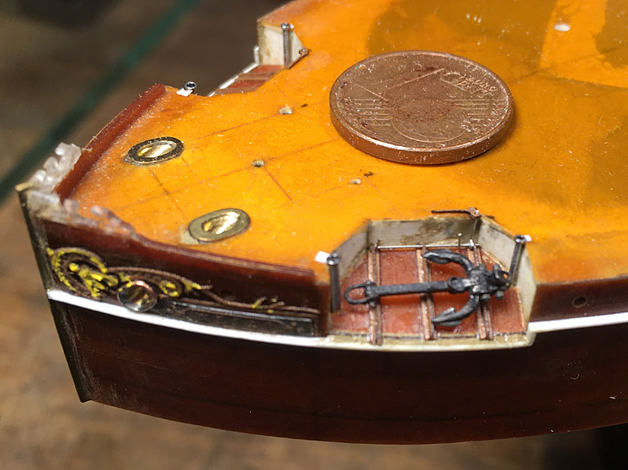
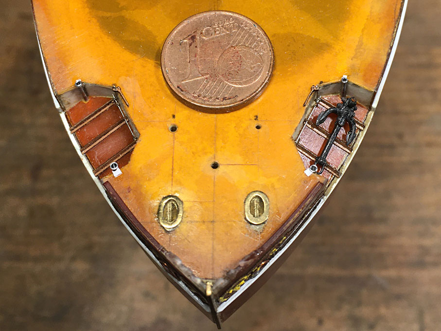
A few of the flimsy and easy to break off details have not yet been installed and some levers to work the mechanisms still have to be fabricated.
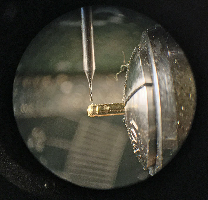
The close-up photographs also show a lot of dust and fluff that need to be cleaned and that the paintwork has to be touched up here and there.

To be continued ...

_________________
Eberhard

Former chairman Arbeitskreis historischer Schiffbau e.V. (German Association for Shipbuilding History)

--------------------------------------------------------------------------------------------------------------------------------------------------------------------------------------------

Image Image Image Image


Report this post
Top
 Profile  
Reply with quote  
PostPosted: Wed Oct 21, 2020 9:07 am 
Offline
User avatar

Joined: Wed Sep 28, 2011 12:04 pm
Posts: 1815
Location: Paris
Ammunition and ammunition handling

Thanks to a book published in 1886 by Carl Galster, we are relatively well informed about the ammunition of the German naval artillery of that time. The WESPE-Class was the only class of ships fitted with the Rk 30,5 cm/l22. According to Galster, three types of projectiles were available for these guns in the late 1870s/early 1880s: a) armour-piercing shells, b) shells with a time-fuse, and b) dummy shells for gun-drill.

All shells had two copper guiding rings that would be squeezed into the rifling. One ring sat shortly above the bottom and the second ring where the cylindrical part would transit into the ogival part of the shell.

The armour-piercing shells were cast in a particular way to harden the steel from which they were cast. They were hollow, but with only a relatively small chamber for powder in the rear part. The nose was cast solid. However, at that time functional impact fuses were not yet available, so the shells were filled with a mixture of sand and sawdust to give the approximate weight distribution as a powder charge would give. The threaded hole for the fuse in the bottom was simply plugged. Armour-piercing shells were painted blue.

The ordinary shell had thinner walls and consequently a larger power-charge. The nose was threaded for time-fuses. It is beyond the scope of this building-log to discuss the fuses in detail, it suffices to say that these were made from brass. Shells were painted red and when actually charged with powder marked with a black ring around the nose.

Image
Shells in handling cradles on the Copenhagen demonstration model (note that in real life the shells would be painted and the museum placed the shell the wrong way around into the cradle)

Dummy shells were ‘seconds’ of ordinary shells filled with a sand-sawdust mixture to give the same weight as a real shell. The hole in the nose was closed with a wooden plug. They were painted black all over.

Powder charges were supplied in cylindrical bags. Each bag weighed 46 kg. Up to two bags could be loaded, allowing to adapt the firing range. The bags were stored and handled in cyclindrical boxes lined with zinc sheet or where made from German silver.

Image
Powder bag and tampion at the demonstration model in Copenhagen

A total of five shells were kept ready in the open barbette. I would assume that these would be only the armour-piercing and drill ones, as the fuse of ordinary shells would be rather exposed to the elements. I set out to make six shells in total, three armour-piercing and two drill-shells, that were stored in their respective racks in the barbette. The sixth is an ordinary shell to be placed in the shell-cradle under the crane.

My preferred steel in the workshop are copper-coated welding rods. The copper-coating is very convenient here, as their diameter of 2 mm is exactly the scale diameter over the copper guiding rings. The nose was turned free-hand with my special Lorch, Schmidt & Co. graver holder. The shells are 4.8 mm long. For the live shell, a little brass button was turned and inserted into a pre-drilled hole in the nose.

Image
Free-hand turning of the shell nose

It not clear, how the heavy shells (weighing around 330 kg) were handled inside the ship and hoisted to the level of the barbette floor. The crane on the gun-carriage does not actually reach over the access-hatch to the shell-store through which the shells presumably were hoisted. The drawings are not clear on the various hatches in the barbette and over the shell-storage, because of various elments being hidden behind others and therefore not drawn. I will have to live with this ignorance.

On the decks, the shells were wheeled around in trolleys. In the Rigsarkivet in Copenhagen a blue-print (in the true sense of the word) for such a trolley has survived. The trolly forms a cradle that can be hoisted by crane to the breech of the gun. At the rear of the gun two hooks are provided (not realised on the model) into which the cradle hooks. The shell then can be pushed into the gun with a rammer.

Image
Gun drill, showing the cradle hooked to the gun (LAVERRENZ, 1900)

The parts for the trolley where laser-cut and assembled using zapon lacquer. Effectively the trolley was built around the shell for rigidity. A hole was drilled into the shell to secure the hoisting ring.

The racks for the ready shells were laminated together from laser-cut pieces and painted white. The retaining bar was made from flattened pieces of 0.3 mm diameter copper wire that was chemically tinned. In theory, each individual shell should have had its own retaining ring (keeping in mind how important it is to restrain these 300 kg beasts in anything but the slightest sea), but after several attempts to put these into place without damaging the paint-work on the shells too much, I gave up. Flattening the wire reminded me of another pending workshop project, namely a micro-rolling mill to produce metal strips of consistent width and thickness from soft wire.

Image
The finished ready-shells (close-up photographs are terribly sobering ...)

Reference:
GALSTER, C. (1886): Pulver und Munition der deutschen Marine.- 99 p., Berlin (E.S. Mittler & Sohn).

To be continued ...

_________________
Eberhard

Former chairman Arbeitskreis historischer Schiffbau e.V. (German Association for Shipbuilding History)

--------------------------------------------------------------------------------------------------------------------------------------------------------------------------------------------

Image Image Image Image


Report this post
Top
 Profile  
Reply with quote  
PostPosted: Thu Nov 05, 2020 4:13 pm 
Offline
User avatar

Joined: Wed Sep 28, 2011 12:04 pm
Posts: 1815
Location: Paris
Postscriptum: in a German Forum I received comments on the man-handling of the shells from a colleague, who observed the available historic drawings more attentively than me. These show in one case a winch located inside the deck-house and marked as ‘shell-hoisting winch’. In another, presumably somewhat older drawing, a substantial bracket is drawn above the shell hoisting hatch. Both features are not shown on the oldest drawings that were the main basis for this model reconstruction. I will install the bracket that was presumably used together with tackle, when the winch was not yet installed.

Anchors
The WESPE-Class was fitted out with two Inglefield bow anchors and (presumably) a standard anchor as stern or reserve anchor. The bow anchors are stowed on chutes and handled with two small cranes on each side.
There is no drawing for the stern anchor, but the drawings seem to show chocks for its storage. There is also a hawse-hole in the stern and a crane above it. So it is likely that there has been a stern-anchor. What is not clear at all is, how the chain would have been handled and there are no stoppers or similar to belay the chain when in use. Neither is there a chain locker drawn in the stern. So there is de facto conflicting evidence.
Inglefield-anchors a are complicated affair, but seem to have been rather popular at the time with the Imperial German Navy. In an instruction book for drawing in shipbuilding a nice detailed drawing of an Inglefield-anchor was found and used as the basis for the model reconstruction. Its size is taken from the WESPE-lithographs in the German Technical Museum in Munich.

Image
Drawing of an Inglefield-anchor from WAAP (1910)

One could have perhaps sawn out the parts from a 0.5 mm brass or styrene sheet, but considering an overall length of the anchors of 12.5 mm this seemed to be a rather daunting task. For this reason the individual parts were drawn for the laser-cutter and cut from 0.12 mm Canson paper. The shaft and other parts were built up from several layers that were cemented together with fast-drying lacquer, resulting in some kind of composite material.

Image
Drawing of the components of an Inglefield-anchor for laser-cutting

The parts then could be easily shaped using diamond and other files. After a certain amount of filing more lacquer was applied in order to prevent the fraying of the paper.
Finally the built-up parts were assembled using lacquer.

Image
One half-completed anchor and parts ready for assembly of the second (I should stop taking these quick-and-dirty close-ups with the iPhone and take out the SLR camera again ...)

Instead of the traditional way of shaping the shackles from wire, I decided to also cut them from paper. The bolts on the smaller shackels would have been too small to represent and were omitted. I think they turned out quite convincingly.
On the other hand, the bolts that keep the parts of the anchor together were turned from steel and blackened before assemply.

The standard anchor possibly could have been cut from brass and soldered together, but then, once it is painted, no one really will know the difference. So I also made the respective designs and employed the laser cutter again. The proportions were taken from an anchor drawing in the Danish Naval Yard archives of the same period.

Image
Drawing of parts for one standard anchor

Image
Laser-cut parts for the stern anchor

The shaft and arms were build up from six layers this time and after lacquering them together the part was shaped using a diamond nail file and various needle and echappement files. As usual more lacquer was applied to keep the paper consolidated.
Finally the flukes were lacquered on and the large shackle also cut from paper attached.

Image
Turning the stock for the stern anchor

The stock was the biggest challenge, as it is only 0.3 mm in diameter in the middle and tapering off. It was turned from thin steel rod. As the anchor will be stowed in the stern, the ball at the end of the bent side will not be visible and therefore left off. The visible ball was formed by a tiny drop of white glue.

Image
Assembled anchors ready to be painted

Image
Painted anchors

To be continued ...

_________________
Eberhard

Former chairman Arbeitskreis historischer Schiffbau e.V. (German Association for Shipbuilding History)

--------------------------------------------------------------------------------------------------------------------------------------------------------------------------------------------

Image Image Image Image


Report this post
Top
 Profile  
Reply with quote  
PostPosted: Fri Nov 06, 2020 6:55 am 
Offline
User avatar

Joined: Sun Nov 16, 2008 7:56 am
Posts: 555
Well done!

_________________
»Als ik kan«
http://artisanmodeler.blogspot.com/


Report this post
Top
 Profile  
Reply with quote  
PostPosted: Fri Nov 13, 2020 7:35 am 
Offline
User avatar

Joined: Wed Sep 28, 2011 12:04 pm
Posts: 1815
Location: Paris
Thanks !

*******************

Display Case

The project has progressed to a point, where soon major parts will be painted and then will have to be protected from dust during the further building process. Hence, I constructed a Plexiglas display case. From another project some 40 years ago I had lots of 2 mm sheets of Plexiglas left over that I now put to good use.

Ideally, the sheets would be cut to size on a table saw, but I do not have one big enough. However, Plexiglas up to 3 mm thick can be scored and then snapped. A procedure recommended by the manufacturer, if you don’t have a suitable saw.

I put a sharp-edged angle-iron along the edge of the work-bench, laid the Plexiglas with the marked-out cutting line exactly over the edge and a heavy steel-ruler exactly (minus half of the thickness of the cutter) over the line and clamped the assembly firmly down. The sheet is then scored a few times with a box cutter, followed by a cutter with a hooked blade until a groove 0.5 to 1 mm deep is made. Finally, you grab firmly with both hands (the faint-hearted may use leather gloves) the part sticking out, take a deep breath and with one decided jerk you break it off. The result is a clean, straight cut with only a little kerf that needs little cleaning up.

Image
Arrangement for snapping Plexiglas sheet in a similar case

In theory, the kerf is desirable. When professional make such Plexiglas cases, they mill on such a kerf to provide room for the cement. The kerf should face inward.

The cement used was Acrifix 192, one of the proprietary cements for real Plexiglas. It is essentially, liquid, uncured Plexiglas and will have the same refractive index once cured so that joints are invisible, when executed professionally. I know the theory (as I have a full version of the manufacturer’s handbook), but my practice is far from perfect. I found that the very old Acrifix 192 I was using has a very short open time and curing begins as soon as a light quantum hits it. Unlike for other formulations, curing is set off by visible light and not only by UV light. It is also very runny and it is easy to smear it over places, where you don’t want it to go, basically fusing into any Plexiglas it hits. So I used it rather sparingly to be on the safe side.

The less than perfect joints don’t matter too much, as the corners will be covered, according to my house-style, in L-shaped brass edges. Still have to mail-order them in Germany, as I have not found a affordable source yet for milled (not drawn !) L-shaped brass here in France. The edges will also add to the strenght of the assembly. There will be also wooden, polished plinth.

The base is a piece of 16 mm fibre-board that I happened to have lying around. The Plexiglas case will be secured to it with two screws eventually.

The case will be completed at a later stage, as for the moment only its function as dust-cover is important.

Image
Plexiglas case in its raw state

To be continued ...

_________________
Eberhard

Former chairman Arbeitskreis historischer Schiffbau e.V. (German Association for Shipbuilding History)

--------------------------------------------------------------------------------------------------------------------------------------------------------------------------------------------

Image Image Image Image


Report this post
Top
 Profile  
Reply with quote  
PostPosted: Wed Dec 02, 2020 10:57 am 
Offline
User avatar

Joined: Wed Sep 28, 2011 12:04 pm
Posts: 1815
Location: Paris
Display case – completion

The display case was given a wooden plinth or frame from four strips of wood with 10 mm x 20 mm cross section. They were carefully cut to length with a mitre-saw and glued together ‘in situ’ to obtain a close fit. The wood was sanded, slightly watered, sanded again and then stained in a light mahagony colour. I decided to follow a simplified French polishing procedure. The wood was given a coat of sanding sealer and lightly sanded, so as not to sand through the staining. Shellac was applied twice with a soft cotton ball and the surface lightly rubbed in between with 0000 grade steel-wool.

A short while ago the mail-ordered brass profiles arrived. I used a 2 mm x 4 mm rectangular cross-section for the bottom frame and 4 mm x 4 mm x 0.5 mm L-profiles for the corners. The bottom frame was first cut to size and the 45° mitres ground on my micro-grinding machine. These allows to achieve a perfect fit at the corners. The four stiles were polished bright with steel-wool and degreased with acetone before glueing them into place using ordinary craft glue of the UHU-brand (it’s solvent-based general glue). The next to go on are the four upper corners. The L-profile are sawn to length, the corners cut away with a side cutter and the precise mitre ground on. During the fitting and re-fitting the stiles are held in place with short lengths of low-tack tape. After glueing these into place, the four vertical corners can be tackled. First the two mitres are fitted into the existing corners, but each stile is cut a tad too long to have material for fitting. It is easier to grind them to length on the square lower end, then on the mitred one.

Image
The finished display case

The Plexiglas and the wooden frame had been pre-drilled on the two narrow sides for a couple of brass screws that will eventually hold the case to the MDF-bottom.

The seascape will be tackled just before painting the hull, so as not to damage the paintwork while sculpting the sea around the hull.

To be continued ...

_________________
Eberhard

Former chairman Arbeitskreis historischer Schiffbau e.V. (German Association for Shipbuilding History)

--------------------------------------------------------------------------------------------------------------------------------------------------------------------------------------------

Image Image Image Image


Report this post
Top
 Profile  
Reply with quote  
PostPosted: Thu Dec 03, 2020 5:42 am 
Offline
User avatar

Joined: Sun Mar 13, 2005 11:51 am
Posts: 2407
Location: Belgium
Great job so far. Love the anchors. :thumbs_up_1: :thumbs_up_1:

Many thanks for the very instructive posts about the construction of the case. Many different transparent materials are available and choosing the right glue isn't always easy. Good to have a reference with experience here. :thumbs_up_1:

_________________
The merchant shipyard


Report this post
Top
 Profile  
Reply with quote  
PostPosted: Sat Dec 12, 2020 2:11 pm 
Offline
User avatar

Joined: Wed Sep 28, 2011 12:04 pm
Posts: 1815
Location: Paris
Thanks for the kind words, Neptune !

**************************************

Further work on the hull

The bulwark in the aft part of the hull is supported by a number of stanchions that were cut from sheet metal and rivetted together. The looks for these stanchions is reasonably well documented on a number of photographs.

Image
The aft part of a WESPE-Class-Boat (Lavverenz, 1900)

The stanchions I had drawn already years ago and depicted the rivetting by surface-etching. The material is 0.1 mm thick nickel silver. They were made in double as mirror images and soft-soldered together in pairs with soldering paste so that the rivetting appears on both sides.

Image
Etched and soldered together stanchions (they are about 5.5 mm high)

The location of the stanchions was marked on the bulwark before this was put into place by thermo-transfer of a drawing, i.e. a laserprinter printout was ironed on. The stanchions were cemented in place with fast-dryining varnish.

Image
The bulwark-stanchions in place

Already a short while ago I had fashioned the boiler-ash chutes by milling to shape little blocks of acrylic glass. They were cemented to the bulwark inside and outside at this stage too.

To be continued ...

_________________
Eberhard

Former chairman Arbeitskreis historischer Schiffbau e.V. (German Association for Shipbuilding History)

--------------------------------------------------------------------------------------------------------------------------------------------------------------------------------------------

Image Image Image Image


Report this post
Top
 Profile  
Reply with quote  
PostPosted: Sun Dec 13, 2020 1:15 pm 
Offline
User avatar

Joined: Mon Jan 10, 2005 5:30 pm
Posts: 5385
Location: Nr Southampton England
...phew!

I have just read up your recent progress--

its always edifying to see the no-compromise nature of your works,
and the mastery of machine tools.

Your set backs-..., bits falling of while constructing-well that is also not unusual ... :Mad_6: :Mad_5:

BRAVO-- its sort of looks like you may be be approaching the finishing straight....?

:thumbs_up_1: :thumbs_up_1:

Jim Baumann

_________________
....I buy them at three times the speed I build 'em.... will I live long enough to empty my stash...?
http://www.modelshipgallery.com/gallery ... index.html

IPMS UK SIG (special interest group) www.finewaterline.com


Report this post
Top
 Profile  
Reply with quote  
PostPosted: Wed Jan 06, 2021 4:49 pm 
Offline
User avatar

Joined: Wed Sep 28, 2011 12:04 pm
Posts: 1815
Location: Paris
Thanks, Jim, for your encouraging words !

*******************************************

Well, steady work, but somehow slow progress ...


Anchor stowage and release gear

The Inglefield-anchors are stored on sort of recessed slides and released by a traditional form of gear. This gear consists of a rotatable iron bar with a couple of thumbs welded on over which the securing chains are hooked. The chains go around the anchor and the other end is shackled to the wall of the recess. The bar is prevented from rotating by lever that is also welded to it. The lever in turn is locked by a rotating claw at the end of a second lever. I suspected this mechanism from the available drawings, but wasn’t shure about it – a German colleague had better eyes than me an could confirm this indeed on the not very clear photographs.
The slide is protected by three T-rails on each from the weight of the heavy anchors.

Image
Recessed slide and anchor release gear – close-up photographs are very sobering :mad_1:

The release gear was fabricated from 0.3 mm diameter tinned copper wire and assembled using varnish. The rails in turn are fabricated from laser-cut strips of Canson-paper that was soaked in varnish. They also function as bearing for the bar of the release gear. I suspect the bearings were a bit more elaborate on the prototype, but I don’t have more detailed information. The locking claw is also a microscopic laser-cut piece. As usual, I had to experiment with different variants of the drawings and settings of the laser-cutter until I managed to produce reasonably clean parts.

Image
Recessed slide with Inglefied-anchor put temporarily in place

Also visible on the photographs are the foundations of the anchor-cranes that will be discussed in the next installment.

Image
View of the bow with the anchor stowage

To be continued ...

_________________
Eberhard

Former chairman Arbeitskreis historischer Schiffbau e.V. (German Association for Shipbuilding History)

--------------------------------------------------------------------------------------------------------------------------------------------------------------------------------------------

Image Image Image Image


Report this post
Top
 Profile  
Reply with quote  
PostPosted: Wed Feb 24, 2021 1:47 pm 
Offline
User avatar

Joined: Wed Sep 28, 2011 12:04 pm
Posts: 1815
Location: Paris
Things never seem to be straightforward, there always seem to be a lot of set-backs caused by technology or materials limitations or, indeed my clumsiness. I seem to loose or destroy many parts during further production steps. Making the boat-davits in my mind seemed simple process, but became rather involved, so that I have to break the reporting on it into two installments. The process is not finished yet ...

Boat-Davits

Originally, the WESPE-Class was provided with four boats, later a small dinghy was added to the complemenent. The very first photograph shows the boats suspended outboard from the davits in the traditional way. A few years later ‘barrings’ or boat-racks were installed above the walk-ways along the deckhouse and the davits elongated accordingly. I gather the boats were prone to damage and prevented the boats from being alongside each other in a ‘parcel’ (as was common practice for flottillas of the same class of boats). For the same reasons at some stage sponsons were installed to protect the screws, which projected beyond the profile of the boats, from damage. However, as I will show SMS WESPE in her original configuration, I choose the shorter, fixed davits.

Image
Micro-Ball-turning on D-bed lathe with ‘right-angle tailstock’ as steady

The davits presumably were hollow, but were not simply curved pipes, but changed their diameter and cross-section along the length. They apparently had a cross-section of a flattened oval in the curved part in order to resist the bending force of the suspended boat. This makes the construction of the davits a bit more involved. At the upper end there is a ball that holds four rings for the stays and the hook of the boat-tackle.

Image
Set-up for ball-turning on D-bed lathe

They started out as 1 mm brass rod (steel would have been better, but is more difficult to drill and to solder ...). The machining steps required a bit of planning in order to keep unsupported areas to a minimum. First the ball was turned in my small 6 mm lathe, where I could use the so-called ‘right-angle tailstock’ as a steady, using my home-made ball-turning attachment. The turning bit was a broken 0.2 mm drill, the end of which was ground at a suitable angle.

Image
Davits after the ball-turning operation

The pieces of brass-rod then were transferred to the dividing head in the micro-mill for 0.2 mm cross-drilling into the ball – four holes were needed in each. Aligning the drill and the ball is a bit tricky, as the drill might slip, bend and break.

Image
Cross-drilling of ball-ends with 0.2 mm drill in the dividing head on the micro-milling machine (view through binocular microscope)

This task provided the incentive to finally commission the antique stereo microscope that I bought a while ago, but never got work properly. By close inspection I discovered that one of the two objectives was misaligned – some previous owner must have tinkered with the adjusting and setting screws. Playing around with the screws, I managed to get proper stereo vision which made the cross-drilling job rather easy and I managed to get the 24 holes without drill break.

Image
Axial 0.2 mm drilling on 6 mm D-bed lathe

The remaining eight holes are axial and were drilled on the lathe.
The next two steps in shaping the davits were also carried out on the lathe. The section behind the bulwark is cylindrical. In order to safely turn down the the relatively soft 1 mm brass to 0.7 mm a so-called ‘Jacot-tool’ was used as a steady. This is essentially a an excentrically mounted hardened drum with groves of known diameter along the perifery. These grooves can be aligned with the centre-line of the lathe. Normally this tailstock-tool is used as a steady to burnish axles and similar watch parts. After each pass, the drum was turned to a smaller groove in order to provide good support while turning down the shaft of the davit.

Image
Set-up for using a ‘Jacot-tool’ as steady for taper turning

In the following step, turning the tapering upper end of the davit, deliberately a groove one size too small, forcing the rod off-centre. This resulted in a slight taper as desired. The procedure was repeated with inreasingly smaller grooves until the upper end reached a diameter of 0.6 mm.

Image
Using a ‘Jacot-tool’ as steady for taper turning

I didn’t take pictures of the next steps. The davits now were taken into a collet in a square collet-holder. Under the stereo microscope the cross-drilled holes at the top were aligned with the sides of the collet-holder. This allowed bending the davit in the corret direction. Bending was effected with bending pliers against a scale-drawing of the davit. That these slighly marred the back of the davit did not matter, as the shape had to be filed anyway. With various very fine files the shape of the curved section of the davit was developed.

To be continued ...

_________________
Eberhard

Former chairman Arbeitskreis historischer Schiffbau e.V. (German Association for Shipbuilding History)

--------------------------------------------------------------------------------------------------------------------------------------------------------------------------------------------

Image Image Image Image


Report this post
Top
 Profile  
Reply with quote  
PostPosted: Mon Mar 01, 2021 3:32 pm 
Offline
User avatar

Joined: Sun Mar 13, 2005 11:51 am
Posts: 2407
Location: Belgium
Quote:
Aligning the drill and the ball is a bit tricky, as the drill might slip, bend and break.


Really??? Looks easy to me :heh: :heh: :heh: :heh: :big_grin: I believe "a bit tricky" is quite an understatement, no idea how to begin with something like that... Pretty sure I'd end up with more hole than ball :big_grin:

_________________
The merchant shipyard


Report this post
Top
 Profile  
Reply with quote  
PostPosted: Sun Mar 07, 2021 4:06 pm 
Offline
User avatar

Joined: Wed Sep 28, 2011 12:04 pm
Posts: 1815
Location: Paris
Well, with 'eye-balling' it went suprisingsly well under the stereo-microscope. One sees any deflection immediately and can reposition the part.


**********************


Boat-davits – Part 2

The davits lock into the mounting plate on deck and are fixed to the rail of the bulwark with a bracket. This arrangement is entirely conjectural, as there is no suitable photographic evidence. The mounting plate is a simple piece of turned and drilled brass. The brackets started as thin discs with a slightly raised hub in the centre. From these discs three sides were milled off on the micro-mill to arrive at a rectangular plate with the raised hub at one end. Nothing spectacular either.

The boat tackle is belayed on a clamp that is fastened to the davit. The clamps were milled from a piece of 3 mm x 3 mm square brass rod (because I didn’t have 2 mm x 2 mm in stock ...). They are so tiny, that it would have been difficult to take pictures of the process. Again this was really only made possible now that I have the stereo-microscope in working order. First, the profile of the clamps was milled along the whole length of the brass, while it was clamped horizontally in my micro-vice. Next the piece was mounted upside down and a groove milled to fit onto the davit. The vice then was clamped vertically in the dividing head of the mill and the clamps sawn off.

The clamps and the bracket were soldered to the davit. For some reason I always struggle with soldering such parts whatever materials and tools I am using ... wanted to use soldering paste, but somehow mine didn’t work. In the end traditional solder did the job.

The eye-bolts were bent from tinned 0.15 mm copper wire. Tinned wire was used to make soldering it into the pre-drilled holes. First I formed the eyes around the shaft of a 0.25 mm drill, but then found that I can form them just with a pair of fine tweezers equally well. The wire ends were cut off flush with a pair of cutting tweezers, but a scalpel on a glass plate would have worked also.

Image
Using a Novotex-clamp to hold the davits for re-drilling

Soldering the eye-bolt didn’t quite work out first for the same reasons. I then tried to cement them in using shellac, but the joint wasn’t strong enough (I don’t have CA around and don’t like it anyway). It took a while until I developed the right strategy. Also, I didn’t dare to drill 0.2 mm right through the spheres, but with control under the binocular it can be safely done. It turned out that I had to re-drill various holes, because they became filled with solder. Holding the davits for re-drilling caused some head-scratching at first, but then I remembered that I had made clamps from fibre-reinforced bakelite (Novotex) for the third hand and took one into a 4 mm collet in the dividing head. This proved to be stiff holding arrangement and watching the drilling under the binocular, allowed the check for any dangerous deflection of the drill.

Image
The finished boat-davits

So on the bottom line, the following strategy would have been best (and was put into practice for some of the davits):
- drill the axial hole first on the lathe, bend the davit and the solder the eye into it;
- then cross-drill horizontally;
- insert an eye-bolt with a long leg and form the other eye with a pair of tweezers, so that both eyes are pulled tightly against the davit;
- solder the pair of eyes;
- cross-drill the vertical hole for the eye-bolt into which the boat-tackle will hook.
- insert an eye-bolt with a long leg and squeeze the leg flat, so that it cannot slip out.
- solder this last eye.
When the soldering is done fast and the other eye are not touched by accident in the process they will stay put.

Image
Boat-davits temporarily installed

To be continued ...

_________________
Eberhard

Former chairman Arbeitskreis historischer Schiffbau e.V. (German Association for Shipbuilding History)

--------------------------------------------------------------------------------------------------------------------------------------------------------------------------------------------

Image Image Image Image


Report this post
Top
 Profile  
Reply with quote  
PostPosted: Fri Mar 12, 2021 5:06 am 
Offline

Joined: Wed Jan 21, 2009 1:51 pm
Posts: 2858
Great work on the davits! :thumbs_up_1: I tried drilling 0.3mm and smaller in brass but my tools don't have the rate of revolutions...


Report this post
Top
 Profile  
Reply with quote  
PostPosted: Fri Mar 12, 2021 6:38 am 
Offline
User avatar

Joined: Wed Sep 28, 2011 12:04 pm
Posts: 1815
Location: Paris
In theory, you need high speeds, but this is more for productivity (and to avoid work-hardening the brass). It is important to have sharp and good-quality drills - I was lucky to find some old stock boxes Titex plus drills from 0.1 mm upwards at a good price. They have a 1 mm shaft, virtually no run-out and are well-ground. The other point is to have a sensitive screw-feed that prevents the drill from being pulled into the brass, resulting in drill-break. And, as I said the stereo-microscope or a strong loupe helps you to detect deflection before it results in desaster.

_________________
Eberhard

Former chairman Arbeitskreis historischer Schiffbau e.V. (German Association for Shipbuilding History)

--------------------------------------------------------------------------------------------------------------------------------------------------------------------------------------------

Image Image Image Image


Report this post
Top
 Profile  
Reply with quote  
PostPosted: Sat Mar 13, 2021 7:05 am 
Offline
User avatar

Joined: Wed Sep 28, 2011 12:04 pm
Posts: 1815
Location: Paris
As I was on the boat-davits I also tackled the anchor-cranes in a similar way.

*********************************

Anchor-cranes

As noted above, the bow anchors are handled with two pairs of cranes that are positioned on either side of the anchor pocket. These cranes will be painted white in compliance will the prescribed livery. Hence, it does not matter what material is underneath and I first attempted to laminate them up from laser-cut Canson-paper parts. There are actually two sets of different cranes, one with three sheaves and one with two sheaves. They were made up from four and three layers of Canson-paper respectively and cemented together with lacquer in the usual way. The sheaves at the end are held by brackets that were lacquered on. Sheaves were turned and lacquered in. However, in the end the result was not as crisp as I had wished for.

Image
Set-up for milling the flats onto the davits

Image
The milling seen through the stereo-microscope

So I turned back to brass, starting with pieces of 1.2 mm diameter wire. A spigot to fit into the sockets already installed on the boat were turned on and the other end received a male centre. The piece then was transferred to the dividing-head on the mill, supported by the tailstock. The four long flat sides were milled on with a small-diametre burr. The flat section is 0.8 mm high and 0.6 mm wide. The sides of the future brackets were milled flat. After re-chucking, a starter slot for the sheaves was cut with a circular saw.
In the meantime, the sheaves of 0.9 mm diameter were turned from the same brass rod and the grooves, which are 0.3 mm apart were marked with a pointed turning-tool. The main craine has three sheaves, while the auxilliary one has two sheaves only. They were all turned in one piece and I did not bother to drill the sheaves for axles.
The brackets on the cranes were bent to accomodate the sheaves, which were soldered in place. The shape of the cranes then were finished with files and abrasive discs in the handheld drill.

Image
The only photograph (blow-up) on which one can discern the belaying point for the anchor-tackle

The tackles are belayed on clamps or belaying pins – the photographic evidence is not clear and on the drawings these were omitted. I decided in favour of cleats as these were easier to make.

Image
Set-up for the first step in making cleats

A piece of 2 mm brass rod was chucked up in the dividing-head set vertically and a flat of 0.3 mm width and 0.9 mm height was milled on. This piece then was transferred to the lathe, where the T-shape and the 0.3 mm diametre spigot were turned. After parting off, the clamp was finished in a pin-vice using small files and an abrasive disc in the handheld drill.

Image
Turning the rough shape of the cleats and their spigot

Image
The cleats filed to shape

As the cleats are fitted to the sides of the davits, 0.3 mm holes had to be drilled for their spigots. I did not want to do this before bending the davits, as it would have weakend them and the hole might become distorted in the process. However, it turned out the davits could be clamped conveniently in the mini-vice in the dividing attachment on the mill.

Image
Set-up for drilling the anchor-cranes

Image
Drilling the anchor-cranes as seen through the stereo-microscope

The cleats were soldered into the holes. This completed the construction of the davits.

Image
The four anchor-cranes in place (they are about 10 mm high)

To be continued ...

_________________
Eberhard

Former chairman Arbeitskreis historischer Schiffbau e.V. (German Association for Shipbuilding History)

--------------------------------------------------------------------------------------------------------------------------------------------------------------------------------------------

Image Image Image Image


Report this post
Top
 Profile  
Reply with quote  
Display posts from previous:  Sort by  
Post new topic Reply to topic  [ 384 posts ]  Go to page Previous  1 ... 4, 5, 6, 7, 8, 9, 10 ... 20  Next

All times are UTC - 6 hours [ DST ]


Who is online

Users browsing this forum: No registered users and 15 guests


You can post new topics in this forum
You can reply to topics in this forum
You cannot edit your posts in this forum
You cannot delete your posts in this forum
You cannot post attachments in this forum

Jump to:  
Powered by phpBB® Forum Software © phpBB Group