The Ship Model Forum

The Ship Modelers Source
It is currently Thu Apr 18, 2024 6:16 pm

All times are UTC - 6 hours [ DST ]


Post new topic Reply to topic  [ 4786 posts ]  Go to page Previous  1 ... 216, 217, 218, 219, 220, 221, 222 ... 240  Next
Author Message
PostPosted: Wed Feb 17, 2021 6:02 pm 
Offline

Joined: Sun Jun 10, 2012 9:07 pm
Posts: 452
pascalemod wrote:
Guys, is there a good solid summary of changes needed for Academie Missouri 1/700 to turn it into New Jersey ca 44-45 when she was painted MS21?

Is Academie kit bad also in terms of the hull?


I looked at some pictures and it looks like the Academy hull form is better than most but is still pretty far off.

You main decision will be whether to do the 44 or late 1945 bridge. The would be a major change. You're also going to have to check the armament an radars.

The Missouri and Wisconsin crammed in a few extra AA guns not on the New Jersey.


Top
 Profile  
Reply with quote  
PostPosted: Thu Feb 18, 2021 4:13 am 
Offline

Joined: Sat Jul 30, 2016 5:33 pm
Posts: 1772
Location: Stockholm, Sweden
bigjimslade wrote:
pascalemod wrote:
Guys, is there a good solid summary of changes needed for Academie Missouri 1/700 to turn it into New Jersey ca 44-45 when she was painted MS21?

Is Academie kit bad also in terms of the hull?


I looked at some pictures and it looks like the Academy hull form is better than most but is still pretty far off.

You main decision will be whether to do the 44 or late 1945 bridge. The would be a major change. You're also going to have to check the armament an radars.

The Missouri and Wisconsin crammed in a few extra AA guns not on the New Jersey.


What is mostly wrong on Academie hull for NJ or Missouri?

I have a round closed bridge from MM. Would that config suit an MS21 NJ?

Or to put it simpler, I wanna build this NJ as attached in picture.


Attachments:
016226.jpg
016226.jpg [ 65.53 KiB | Viewed 2130 times ]

_________________
- @Shipific on IG
my gallery
Top
 Profile  
Reply with quote  
PostPosted: Thu Feb 18, 2021 2:36 pm 
Offline

Joined: Sun Jun 10, 2012 9:07 pm
Posts: 452
Here is the stern taken from the original plans. Note that under the stern the plating is flat relative to the centerline (halfsiding). The rudder sits in a flat area. It appeared to me that the hull was curved there.

I did not attach the docking keel (or cut out the stern tubs) here but that is also omitted in the kit.

Attachment:
ViewCapture20210218_143115.jpg
ViewCapture20210218_143115.jpg [ 60.28 KiB | Viewed 2105 times ]


It looks like the square bridge in the photo. That would make it 1945.


Top
 Profile  
Reply with quote  
PostPosted: Fri Feb 19, 2021 12:05 pm 
Offline

Joined: Sat Jul 30, 2016 5:33 pm
Posts: 1772
Location: Stockholm, Sweden
bigjimslade wrote:
Here is the stern taken from the original plans. Note that under the stern the plating is flat relative to the centerline (halfsiding). The rudder sits in a flat area. It appeared to me that the hull was curved there.

I did not attach the docking keel (or cut out the stern tubs) here but that is also omitted in the kit.

Attachment:
ViewCapture20210218_143115.jpg


It looks like the square bridge in the photo. That would make it 1945.


Yes, the stern section Im clear on (i saw your post earlier). What I wonder about is the bow shape. Is that alright?

Good that the bridge is square - I can use the one from Missouri without changes, then. (or?)

_________________
- @Shipific on IG
my gallery


Top
 Profile  
Reply with quote  
PostPosted: Fri Feb 19, 2021 3:21 pm 
Offline
User avatar

Joined: Mon Jan 10, 2005 6:00 pm
Posts: 12143
Location: Ottawa, Canada
Pretty sure it's the round bridge in that photo - when NJ got her square bridge, she was also repainted into the two-tone MS 22 scheme.

_________________
De quoi s'agit-il?


Top
 Profile  
Reply with quote  
PostPosted: Fri Feb 19, 2021 6:04 pm 
Offline
User avatar

Joined: Mon Jan 10, 2005 1:52 pm
Posts: 60
Location: Mississippi
NJ still had the round bridge until at least April of 45 when she was relieved by Iowa to go in for her refit. Here is NJ going through inclining in June of 45 with the square bridge. Chad

http://navsource.org/archives/01/062/016293.jpg

_________________
In war there is no substitute for victory.

USMC-2531 1991-1999
USN ABE2 2013-Present


1/96 Missouri 1944
1/96 Pennsylvania 1941
1/96 Yorktown 1944
1/96 Oscar Austin DDG 79 2013


Top
 Profile  
Reply with quote  
PostPosted: Mon Mar 01, 2021 11:59 am 
Offline

Joined: Sun Jun 10, 2012 9:07 pm
Posts: 452
I was able to get some photographs of the roller track in the turret yesterday.


Top
 Profile  
Reply with quote  
PostPosted: Sat Mar 06, 2021 12:54 am 
Offline

Joined: Mon Jun 01, 2015 8:49 pm
Posts: 8
I am starting on the 1/700 Tamiya Iowa (1944), and had a painting question: Would the Deck Blue be any lighter or darker when comparing the wooden parts of the deck and the metal plate parts of the deck? My first thought is that there would be some variation after some weathering had occurred, but I'm not sure. Also, would the individual wooden deck planks have lighter/darker tones also? Thanks in advance for any info!


Top
 Profile  
Reply with quote  
PostPosted: Sat Mar 06, 2021 1:40 am 
Offline

Joined: Wed Jan 02, 2013 1:15 am
Posts: 5011
Probably not a lot of variation,however carrier decks which got a lot of wear showed it! On my Alaska,(1:192) I have the wooden decks imperceptibly lighter than the steel decks. I have no specific information to justify this except the steel starts off as a smoother surface.


Top
 Profile  
Reply with quote  
PostPosted: Sat Mar 06, 2021 7:55 am 
Offline

Joined: Thu Apr 28, 2016 11:03 am
Posts: 161
I slightly vary the colors, based on photos, to indicate the way light reflects off of the different materials.


Top
 Profile  
Reply with quote  
 Post subject: Re: 1983-1991 timeframe
PostPosted: Sat Mar 06, 2021 5:03 pm 
Offline

Joined: Sun Jun 10, 2012 9:07 pm
Posts: 452
harrier1961 wrote:
Ok guys, I have received help before, so here goes my latest question. What changes, if any, were made to the New Jersey from the time it was recommisioned in 83/84 to when it was decomissioned in the early '90's?


Some the top of my head:

1. The paravane chin was removed.
2. Addition of cranes for reloading harpoons at the sides of the stack.
3. The aft harpoon platform was widened.
4. 100ll fuel tank, Pioneer hangar, and Pioneer antennas
5. Various antenna changes.
6. Mountings for 25mm guns.

One of the research problems is that the original plans for the New Jersey in the 1980's were made off of plans for the USS Iowa. The baseline plans are then a mixture of the two ships. It appears that the New Jersey never had a foremast that extended below the 010 level (where it is now). Her sisters go down to the 08 level and this is shown for the NJ in the originals. So is the 03 armored conning tower, the double vent at the fantail and the useless step down at the aft end of Broadway.

From there all the plans are incremental and you can never be certain whether a change was actually made.


Last edited by bigjimslade on Mon Mar 08, 2021 12:09 pm, edited 1 time in total.

Top
 Profile  
Reply with quote  
PostPosted: Sat Mar 06, 2021 8:02 pm 
Offline

Joined: Wed Jan 02, 2013 1:15 am
Posts: 5011
I haven't found the reference, but my recollection (subject to error) was the WWII Carrier decks were stained rather than painted and would tend to be duller and less saturated than the deck paint. Let you know if I find out anything definitive.

Found this:

aircraft carriers began applying a dark blue-gray flight deck stain (#250) approximately the same color as Deck Blue, together with a stain approximately Ocean Gray for flight deck markings (#251).[14] The Pacific Fleet's surface ships, less carriers, were ordered into Measure 11 on 16 December 1941. The order also substituted 5-N for 5-S [15]

Guessing (hazardous) that cruisers and battleships also used the same stain.


Top
 Profile  
Reply with quote  
PostPosted: Wed Mar 10, 2021 12:26 pm 
Offline
User avatar

Joined: Tue Sep 29, 2020 4:35 pm
Posts: 1720
Location: Bretagne, France
Maybe someone can help me, I'm looking for the position of the navigation lights on the Missouri, a drawing would be ideal, and the bridge lights too.

_________________
Pascal

•Battleship Bretagne 3D: https://vu.fr/FvCY
•SS Delphine 3D: https://vu.fr/NeuO
•SS Nomadic 3D: https://vu.fr/tAyL
•USS Nokomis 3D: https://vu.fr/kntC
•USS Pamanset 3D: https://vu.fr/jXGQ


Top
 Profile  
Reply with quote  
PostPosted: Wed Mar 10, 2021 12:53 pm 
Offline
User avatar

Joined: Mon Jan 10, 2005 6:00 pm
Posts: 12143
Location: Ottawa, Canada
In WWII, they're here:
Attachment:
mo sidelight.jpg
mo sidelight.jpg [ 203.93 KiB | Viewed 1577 times ]


For the 80s modernization, it seems they ('sidelights') were moved down to the 01 level (taken from New Jersey's plans on HNSA):
Attachment:
nj sidelight.jpg
nj sidelight.jpg [ 111.48 KiB | Viewed 1577 times ]


The museum Wisconsin has them quite prominently but I'm not sure how reflective they are of the original location: http://www.navsource.org/archives/01/016442.jpg

_________________
De quoi s'agit-il?


Top
 Profile  
Reply with quote  
PostPosted: Wed Mar 10, 2021 2:37 pm 
Offline
User avatar

Joined: Tue Sep 29, 2020 4:35 pm
Posts: 1720
Location: Bretagne, France
Thank you Timmy for taking the time to answer me quickly, to post pictures and the plan. :thumbs_up_1:

_________________
Pascal

•Battleship Bretagne 3D: https://vu.fr/FvCY
•SS Delphine 3D: https://vu.fr/NeuO
•SS Nomadic 3D: https://vu.fr/tAyL
•USS Nokomis 3D: https://vu.fr/kntC
•USS Pamanset 3D: https://vu.fr/jXGQ


Top
 Profile  
Reply with quote  
PostPosted: Thu Mar 11, 2021 7:53 am 
Offline

Joined: Sun Jun 10, 2012 9:07 pm
Posts: 452
Iceman 29 wrote:
Maybe someone can help me, I'm looking for the position of the navigation lights on the Missouri, a drawing would be ideal, and the bridge lights too.


For the NJ currently:

Masthead lights: Forward end of foremast and top of discone
Stern and wake lights: Box at maindeck, centerline stern
Anchor lights: Top of jackstaff and ensignstaff
Steering light: Middle of jackstaff
Sidelights: Saluting gun platforms
Blinking light: Ends of foremast yardarms
Various: Stub mast on foremast


Top
 Profile  
Reply with quote  
PostPosted: Mon Mar 15, 2021 12:23 pm 
Offline

Joined: Sun Mar 14, 2021 10:22 pm
Posts: 5
Hello. I posted a short introduction in the General Forum and asked a question. I decided I should proceed here with my follow up question.

I have started the Trumpeter 1/200 USS Missouri

The photo below shows numbers painted on the hull. It appears that Trumpeter placed holes in the hull at the same location as the numbers on the actual ship. I can only guess that the holes are meant to represent the numbers. That doesn’t make sense to me. Why not just a decal?

http://www.navsource.org/archives/01/016308b.jpg

For anyone else that has this kit, am I correct in assuming the holes somehow represent the numbers that one would find on the actual ship?

I look forward to being part of this forum and in particular this thread.
Thanks,
Greg


Last edited by Timmy C on Mon Mar 15, 2021 2:47 pm, edited 1 time in total.
made link clickable [just leave it alone]


Top
 Profile  
Reply with quote  
PostPosted: Mon Mar 15, 2021 6:21 pm 
Offline
User avatar

Joined: Mon Nov 18, 2013 3:41 pm
Posts: 2948
Location: Mocksville, NC
Greg,

Strange moniker (Mr. Nobody) :scratch: Sometimes when I'm out in public I wear a nametag that says "N. Cognito"......................... :doh_1:

Anyhow, more to your question re. the hole in the hull - say, that might be a good Beatles-type of nautical disaster song....has all the earmarks... :big_grin: OK, must be the COVIDs got me!!!!

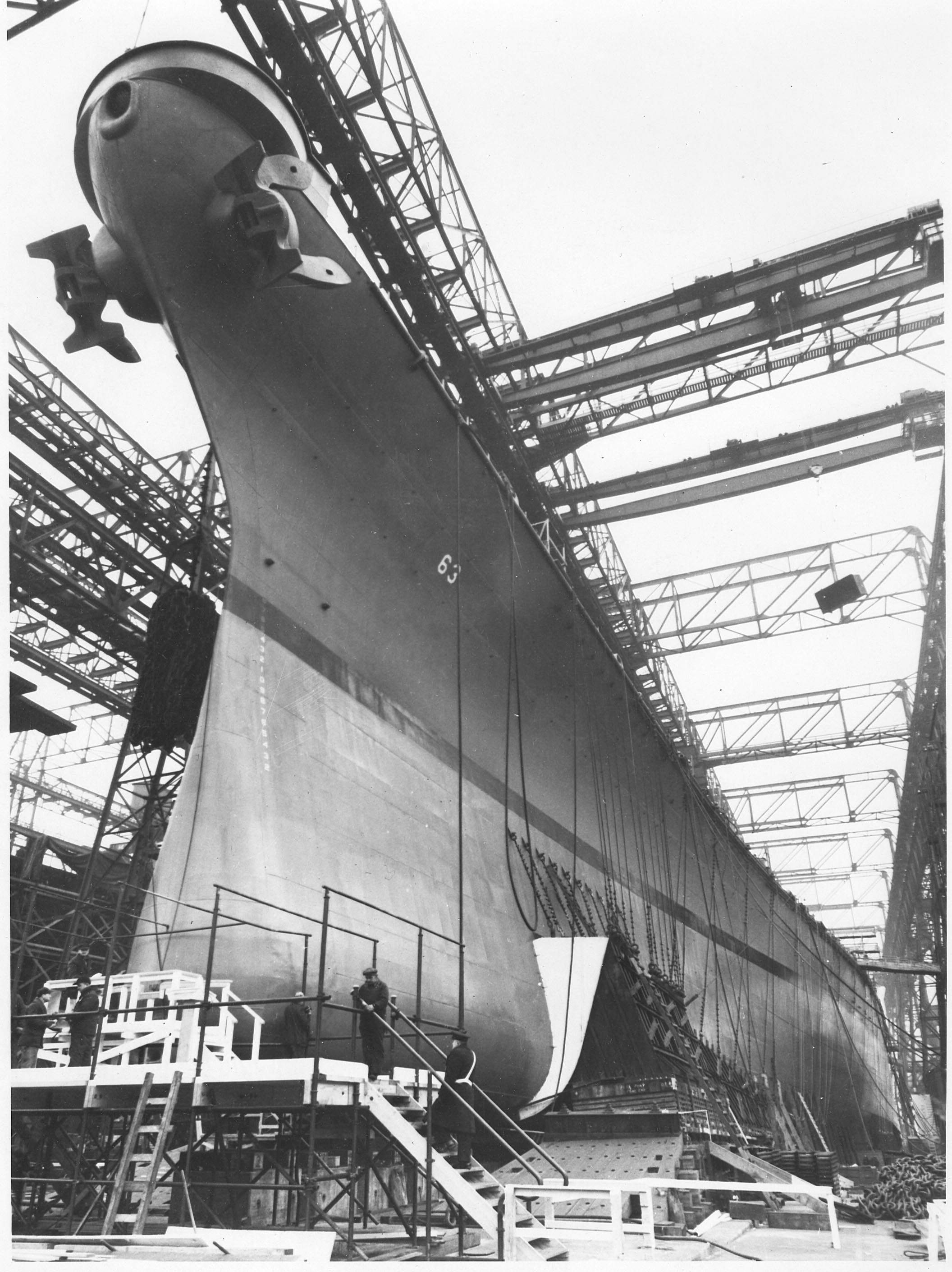
About the hole - here is a picture of the beginning stage of my build back in 2012 - just so we're talking about the same hole, right??? The hole is located about an 1" to the right of the hull joint, correct?
Attachment:
Bow in Place (Large).JPG
Bow in Place (Large).JPG [ 65.21 KiB | Viewed 1365 times ]

If memory serves me right, this is just ONE of several holes, slots, indentions, etc. that you'll find in the kit that has no reference at all in the instruction manual. Why is it there? Well, it's there because of 3rd party accessories that are produced to enhance the basic kit. At least, this is my theory on it based on having purchased the Pontos Detail Up kit - the items in that upgrade matched quite clearly the "unknown" types of hull indentions you describe. I have another theory about this and that is that the kit mfgr is somehow in cahoots with these 3rd party providers (whoever they are) and someone is getting a kickback somewhere each time you buy one of their upgrade offers. When the kit first came out in the early 2000s, Pontos was the only 3rd party mfgr. to offer a MISSOURI kit upgrade so I'm pretty sure they are the ones in bed with Chicken Chow Mein, if you catch my drift. :cool_2:

Hope this helps - my build is located somewhere in the completed forum and also on the SMF Gallery - look for 1/200 USS NEW JERSEY (1967-68) ETC. - I did a 6 year project on her using this kit as the basis to begin with. Also, over on Works in Progress, create a build log so we can see what's happening in Mr. Nobody's shipyard. :thumbs_up_1:

Hank

_________________
HMS III
Mocksville, NC
BB62 vet 68-69

Builder's yard:
USS STODDARD (DD-566) 66-68 1:144, Various Lg Scale FC Directors
Finished:
USS NEW JERSEY (BB-62) 67-69 1:200
USN Sloop/Ship PEACOCK (1813) 1:48
ROYAL CAROLINE (1748) 1:47
AVS (1768) 1:48


Top
 Profile  
Reply with quote  
PostPosted: Mon Mar 15, 2021 6:33 pm 
Offline
User avatar

Joined: Mon Jan 10, 2005 6:00 pm
Posts: 12143
Location: Ottawa, Canada
Mr. Nobody's talking about the vertical holes near the stem where you've got your green putty - the numbers he's referring to are the draft markings.

_________________
De quoi s'agit-il?


Top
 Profile  
Reply with quote  
PostPosted: Mon Mar 15, 2021 9:43 pm 
Thanks for the reply Hank. As Timmy C stated it is the vertical holes that you filled in with putty. I had come to the conclusion that I would fill them in as well. I have the Pontos set. The included instruction aren’t to helpful with this but if you pull the instruction up online you are able to zoom in and make the small print and details large enough to see. The instruction show dry transfers that they supply, applied to the same location as the holes. I still don’t understand the reason for the holes but they do provide a good way to determine where the boot line goes and the decal. Before I loose their location with putty and paint I will make a template or take notes as to their location so that I can place the dry transfer decals properly.

I am considering a Work in Progress log. I have followed many well documented builds. Mine I’m afraid, would not be one of those. I just know my limitations. I do like the idea of a periodic update and I do have a few ideas I would like to share as well.

Thanks for the help
Greg


Top
  
Reply with quote  
Display posts from previous:  Sort by  
Post new topic Reply to topic  [ 4786 posts ]  Go to page Previous  1 ... 216, 217, 218, 219, 220, 221, 222 ... 240  Next

All times are UTC - 6 hours [ DST ]


Who is online

Users browsing this forum: No registered users and 77 guests


You can post new topics in this forum
You can reply to topics in this forum
You cannot edit your posts in this forum
You cannot delete your posts in this forum
You cannot post attachments in this forum

Jump to:  
Powered by phpBB® Forum Software © phpBB Group