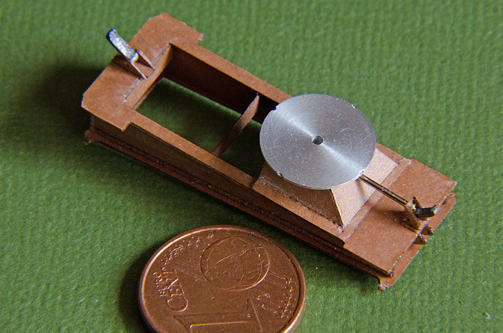
Folding tool update
After the first use of the tool, I immediately made a couple of modifications, which however, I had expected to introduce anyway.
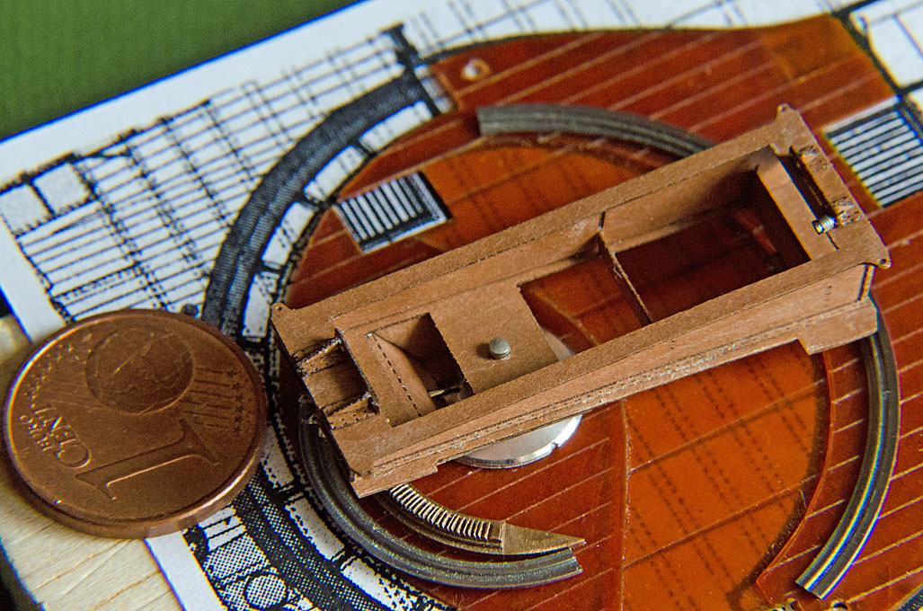
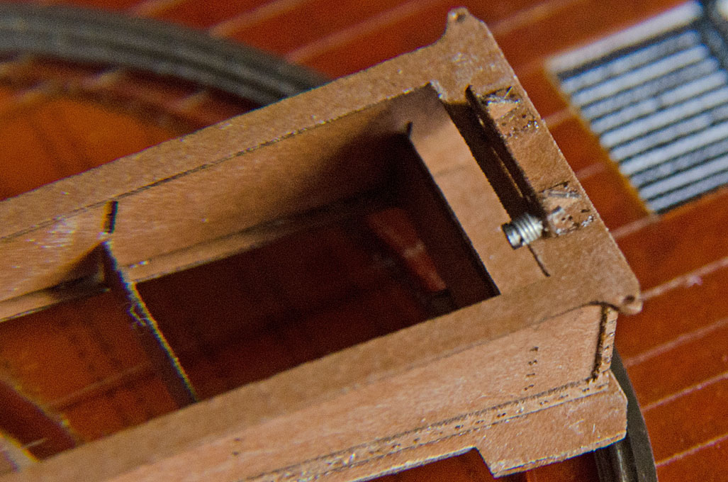
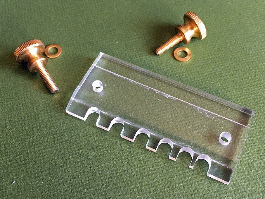
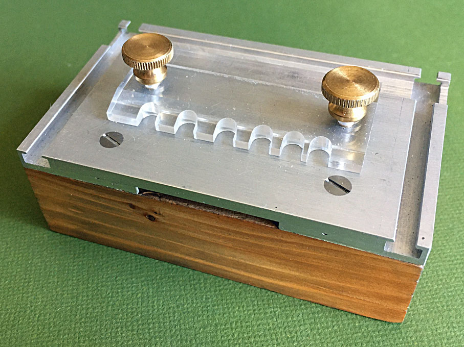
When working with cardboard or paper one needs to �overbend� the folds somewhat, so that they stay at the desired angle. This is different to working with soft sheet-metal. Styrene sheet also will have this spring effect. Therefore, the folding edges were given a 10� clearance angle. An angle of 15� may have been even better, but it works with the 10�. The edges are not really weakened by this.
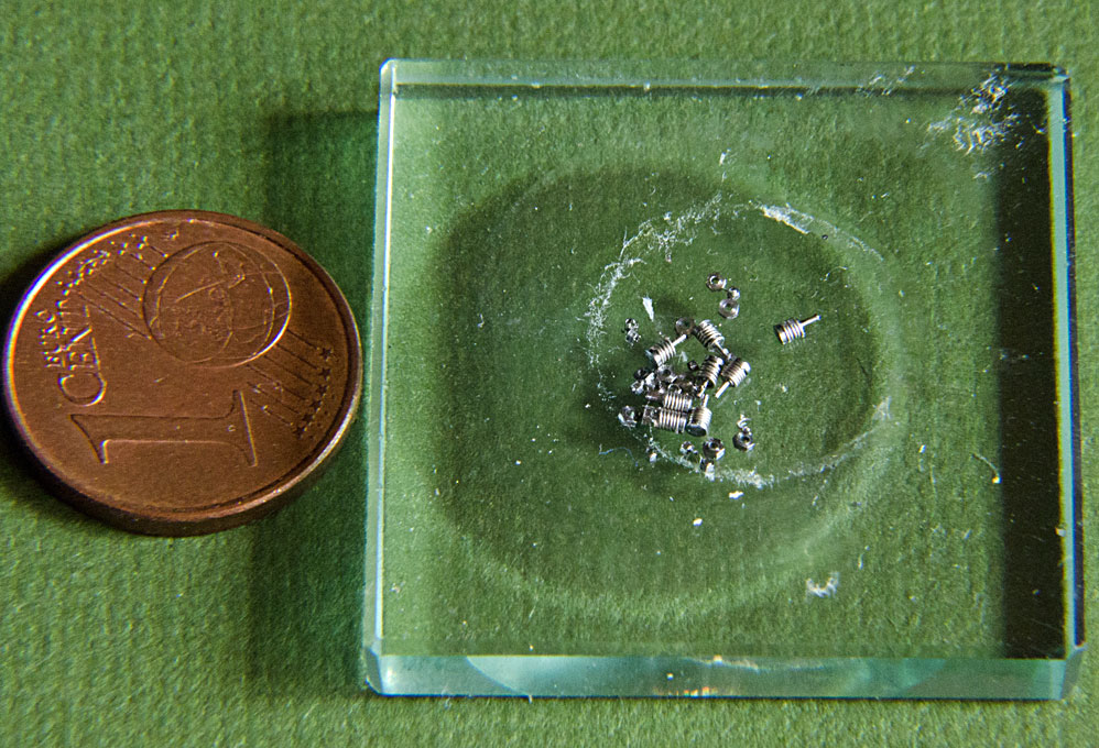
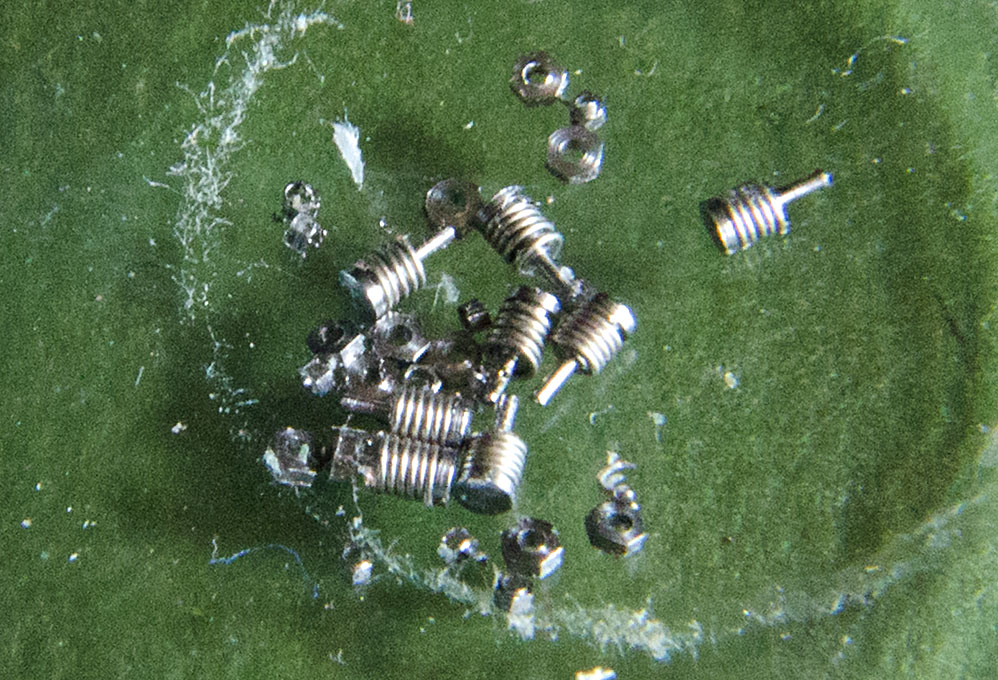
The second modification was to place a spring washer under the folding ruler. I had in mind to do this right away, but could not find them in the first place. The washers lift up the ruler a bit, so that it is easier to slip the material under it.
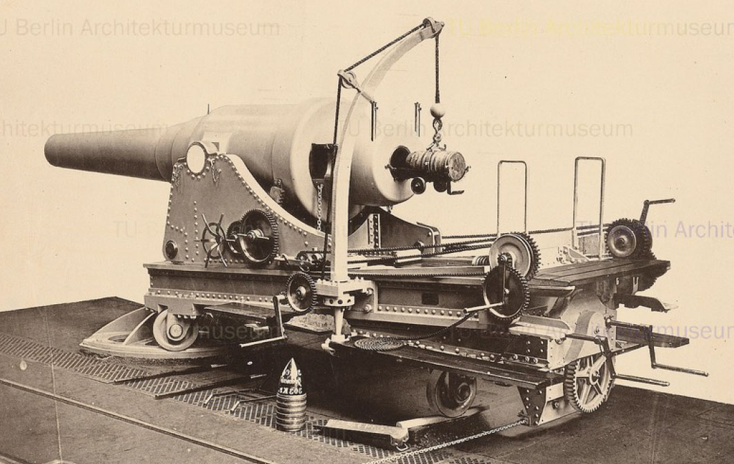
Gun operating platforms and gratings
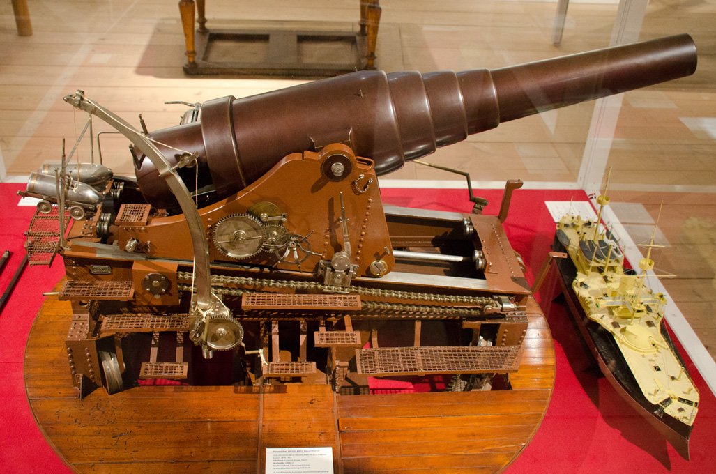
The gun is mounted effectively on a turntable, so that platforms for crew are needed to give them access to the gun, while is being trained left or right. These platforms are made of wire gratings that are placed into angle-iron frames. The frames are suspended from the lower carriage by brackets. The pictorial evidence (photographs, drawings) is not detailed enough to fully understand what the brackets actually looked like and how and where exactly they were attached to the lower carriage frame. Some additional information is given by the Danish instruction model and the Russian clones in Suomenlinna fortress, but the carriages of these guns differ in detail from that on SMS WESPE. So the reconstruction of these platforms remains somewhat conjectural.
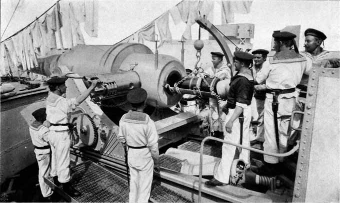 Crew standing on the gratings and operating the gun
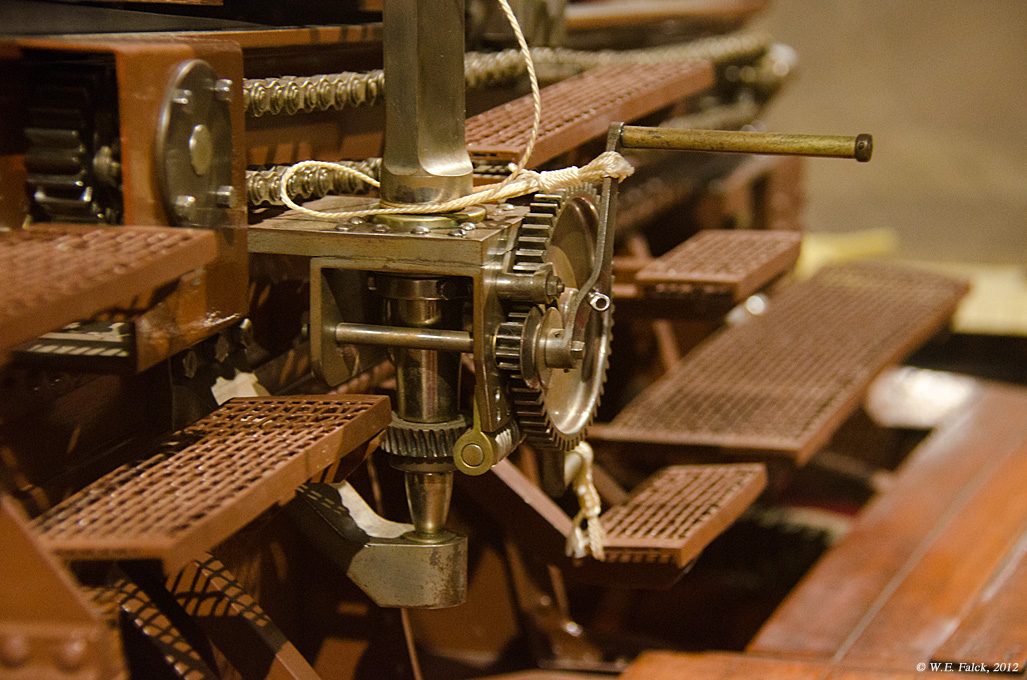 Gratings of the Danish instruction model
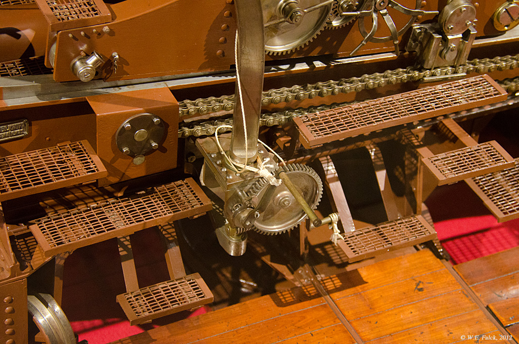
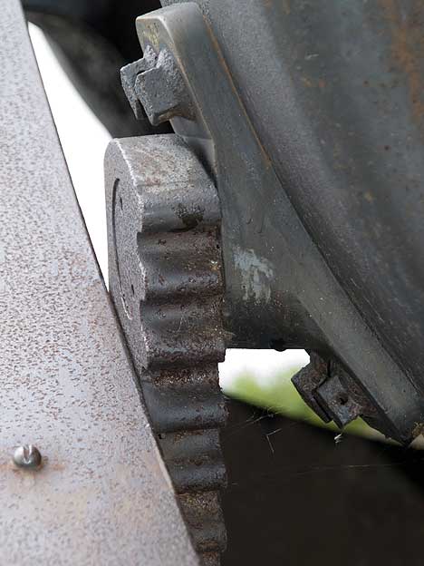
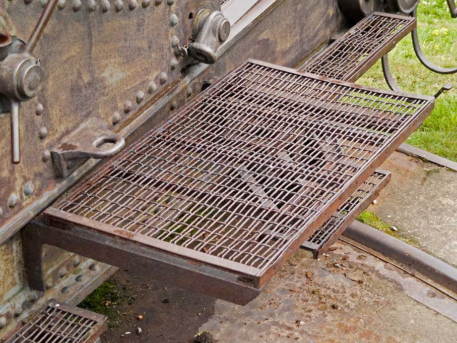 Detail of gratings on a gun in Suomenlinna fortress
There are 13 gratings and steps in total, plus the platform for the gun-layer. The original plan was to photo-etch the frames from brass sheet, but with the arrival of the laser-cutter I changed this plan. The drawings were modified accordingly. The obvious solution to simulate the angle-iron frame was to design an open frame and then fold-up the vertical parts of the angle. However, it proved impossible to fold the narrow, 0.3 to 0.4 mm strips consistently and without distortions. Not sure this would have worked with the PE parts either. It was then decided to make the open frame and the vertical parts separately as narrow strips and glue them together with lacquer. After several iterations of drawings and laser-cutter settings to arrive a workable width of the strips etc. I arrived at an acceptable solution, albeit the �angle-irons� are somewhat over-scale.
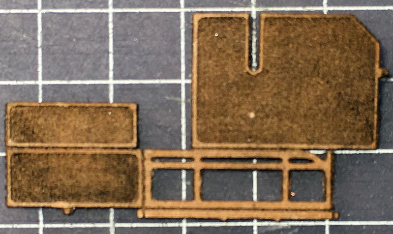
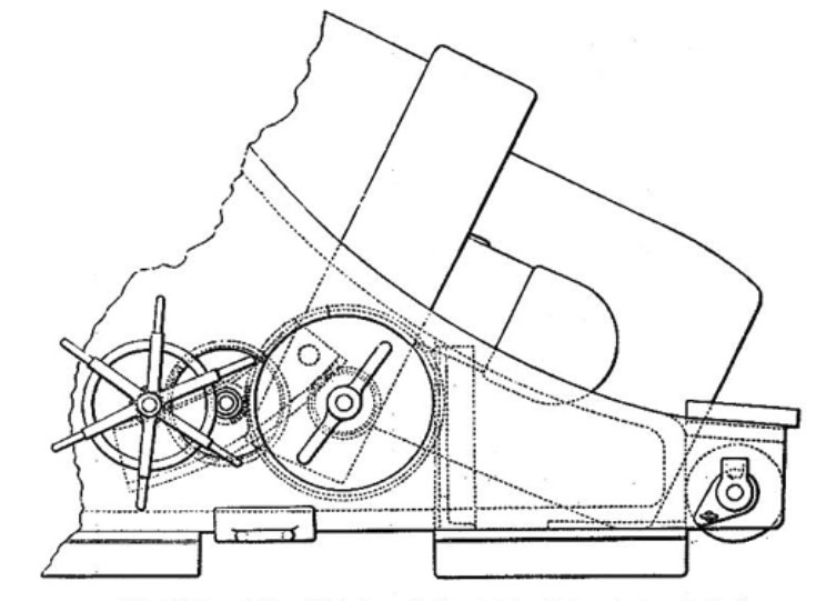
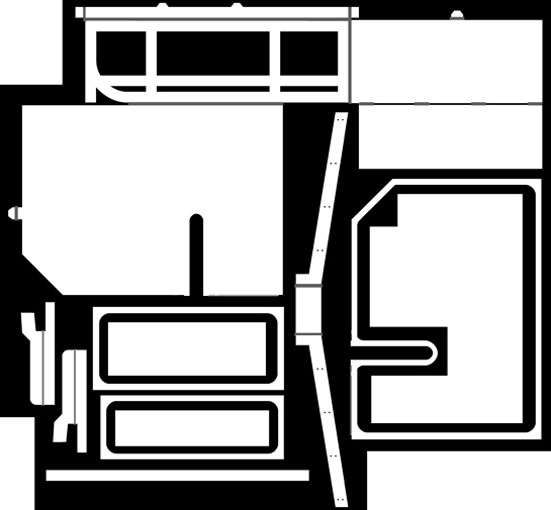 Example of a drawing for the gratings and their supporting brackets
Assembly was a slow and nerve-wracking process. I did not manage to do more than one grating per evening and it involved a lot of (mental) foul language. Eventually, I got them all together. Zapon-varnish was used throughout the assembly. The finished parts are surprisingly strong
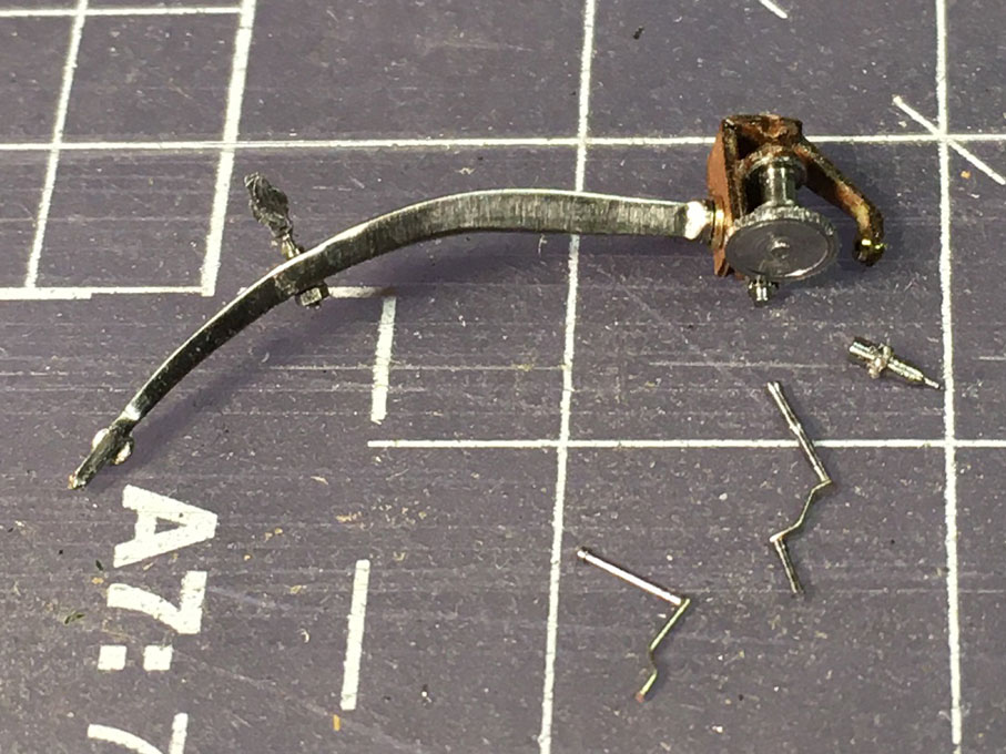
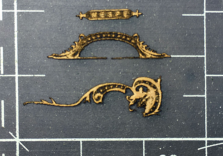
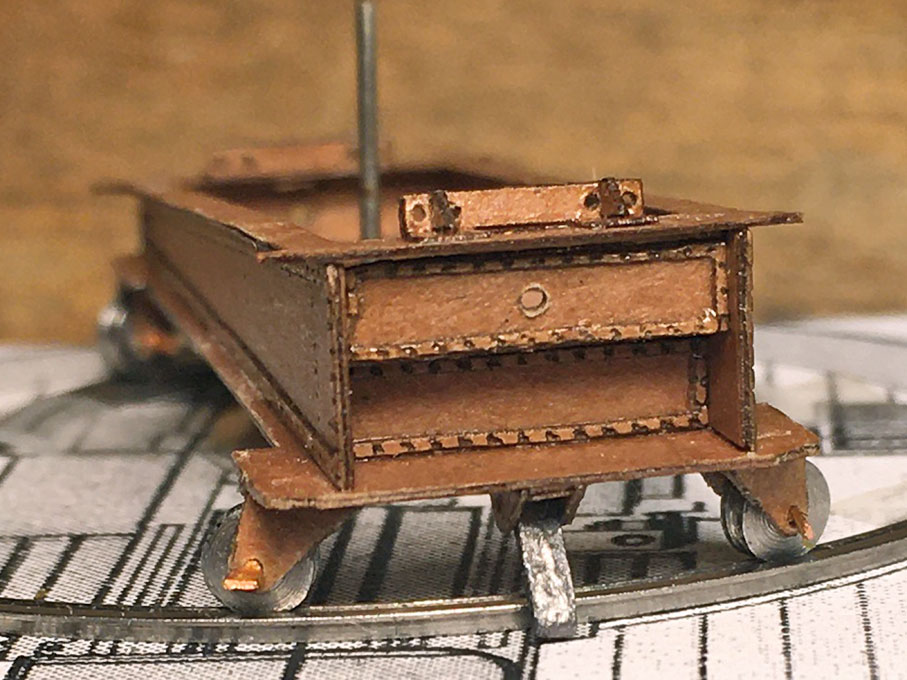
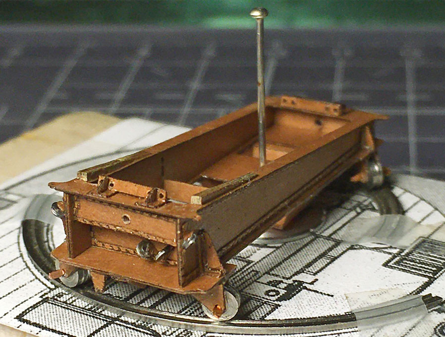
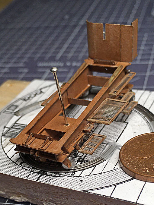
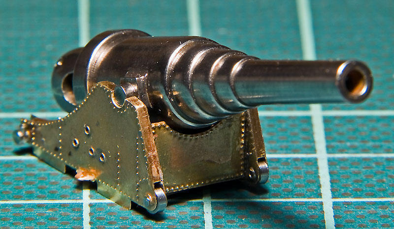
 First Version with engraved surfaces of the platform for the gun-layer
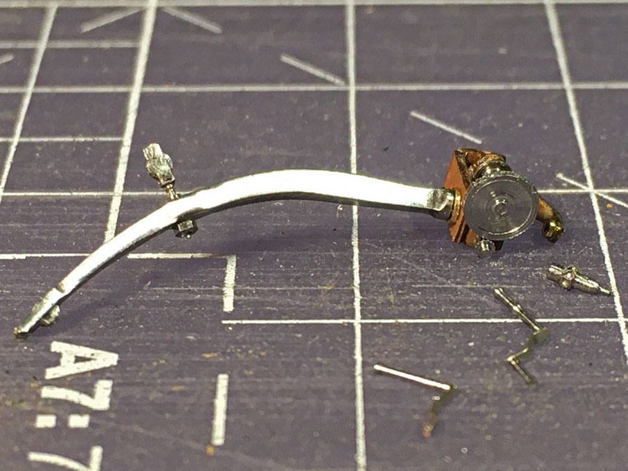
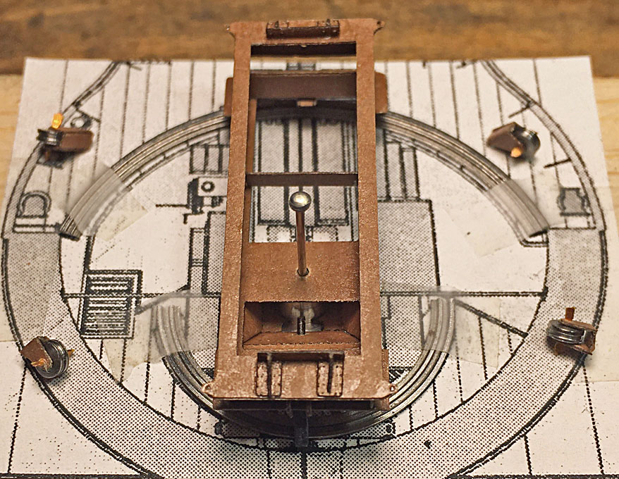
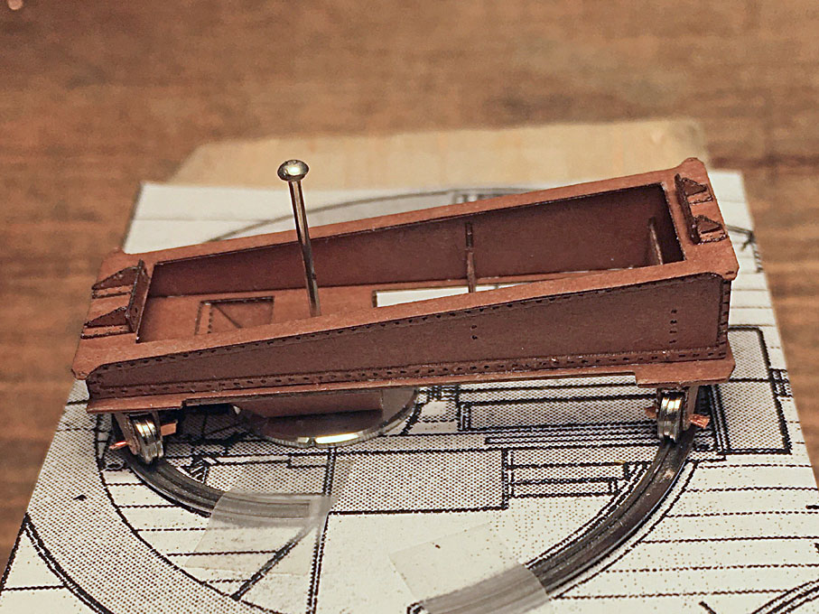
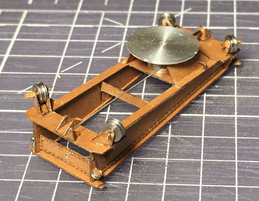
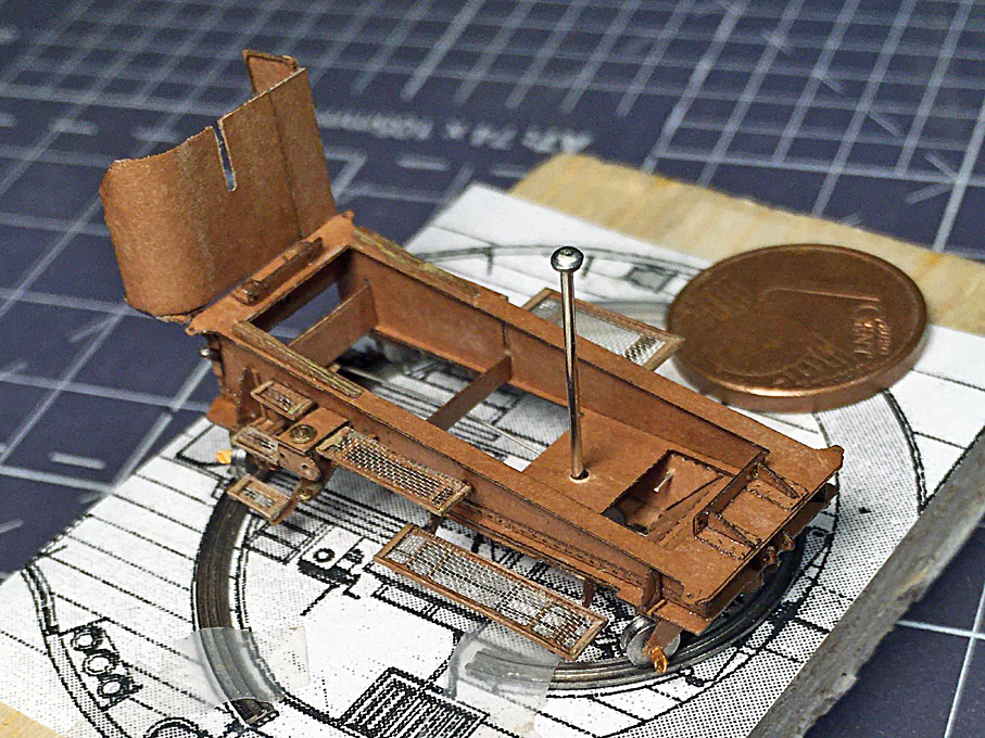
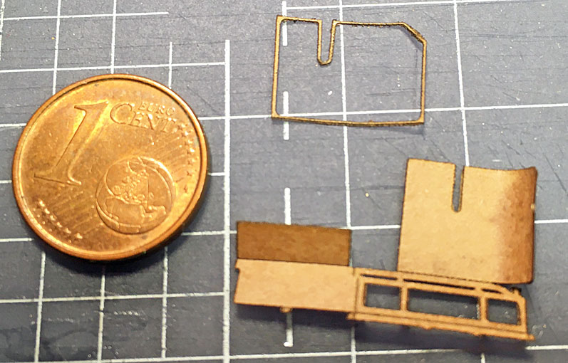 Final Version of the platform for the gun-layer (5 mm grid on the cutting-mat)
The original plan was to simulate the wire-mesh of the gratings by real wire-mesh and I obtained from wires.co.uk some really fine mesh in brass and steel. The idea was to pull every second wire in one direction, as the original mesh was rectangular. It proved, however, very difficult to cut such small pieces (sometimes only 1.5 mm wide) from the wire-mesh. Then a present to wife in form of a box with various (fruit) teas came to my rescue: some of the teas came in bags made from extremely fine but lightly woven fabric. I do not know what material it is, but as it dissolves in acetone, it is probably cellulose acetate silk or Rayon. Such fabrics are also used in silk-screen printing and I had not chanced upon the tea-bags, I would have looked there. This silk-screen or fabric can be precisely and easily cut with a new scalpel blade. The small pieces of fabric were dropped into the frames and fixed at the edges with a light touch of varnish.
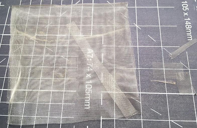 Tea-bag fabric
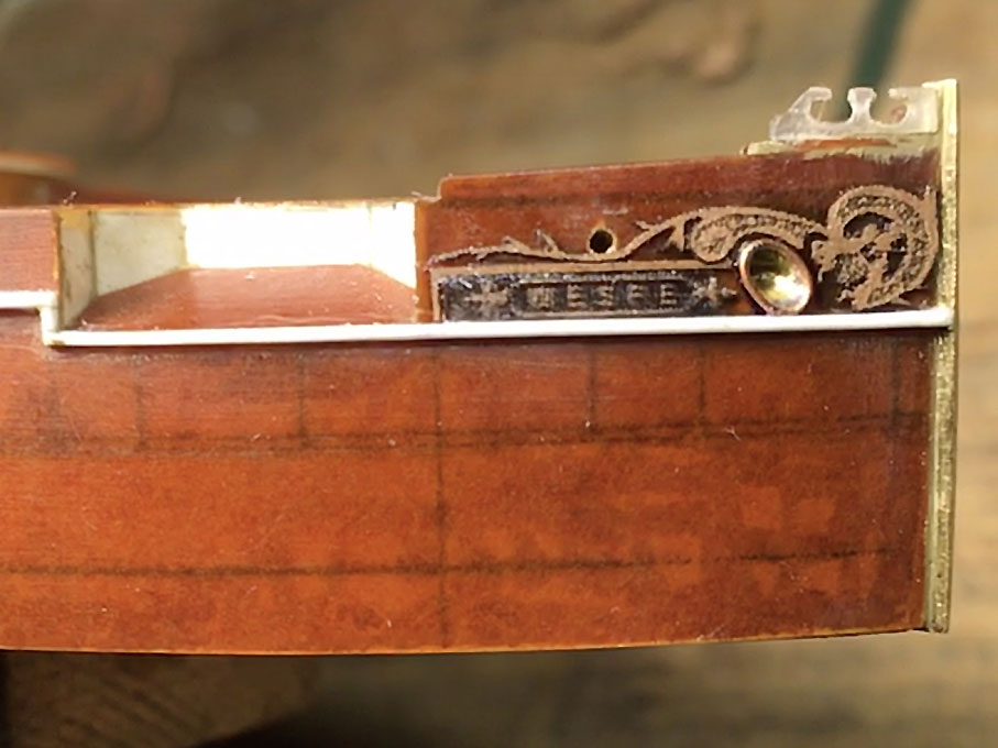
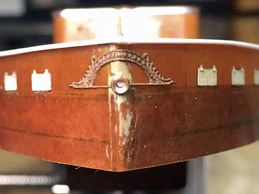
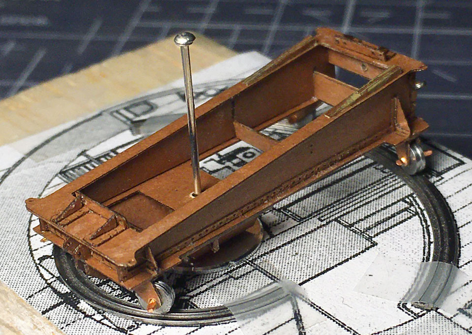
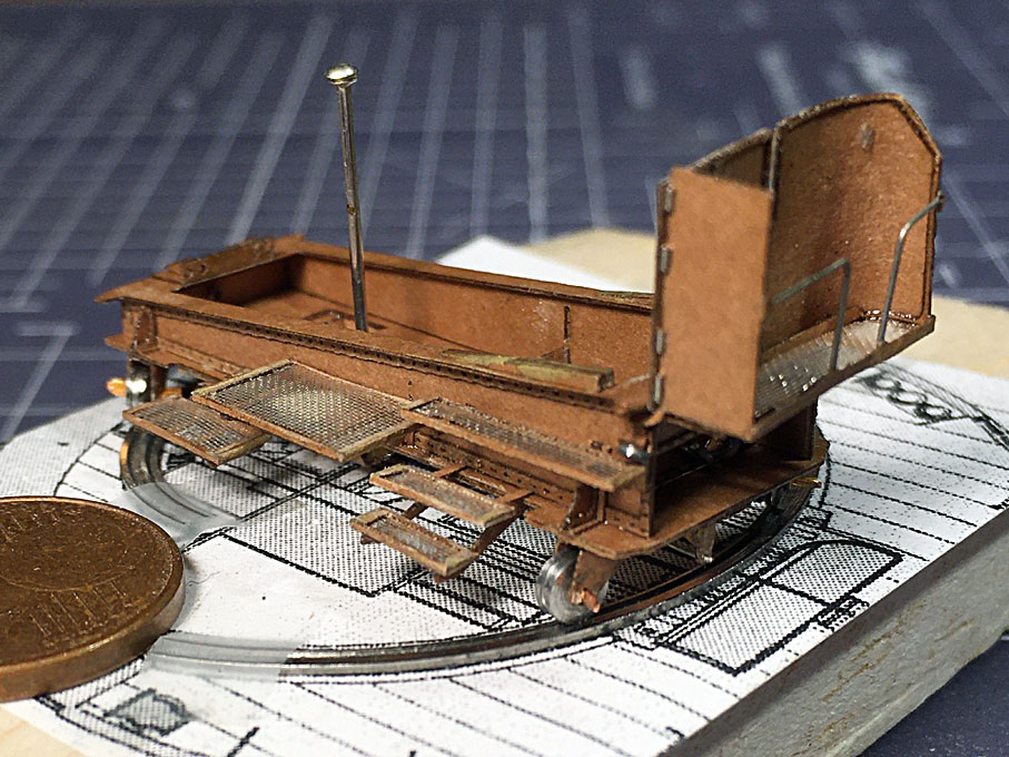
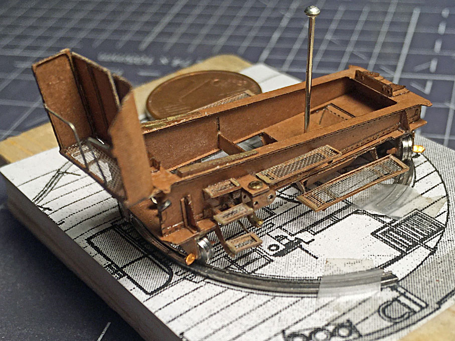
The platform for the gun-layer is a more complex structure. A 5 mm sheet-metal armour shield is meant to protect him from shrapnel and small-arms fire. The armour shield is reinforced at the edges with rivetted-on metal strips. The original plan was to produce this as a surface-etched part. I realised that the laser-cutter interprets half-tone images as instructions to modulate the laser power so that it does not cut all the way through. Laser-engraving in other words. It did produce the desired effect, albeit with the engraved surface being rather rough due to the digitising effect. However, this part then was so thin and flimsy, that it would not stay in shape, when attempting to shape the round corner. I reluctantly accepted that it would be somewhat over-scale in thickness and cut the armour shield and the reinforcing strips separately. They were glued on top of each other with varnish and then the round of the shield formed over a rod. Folding and gluing completed the process.
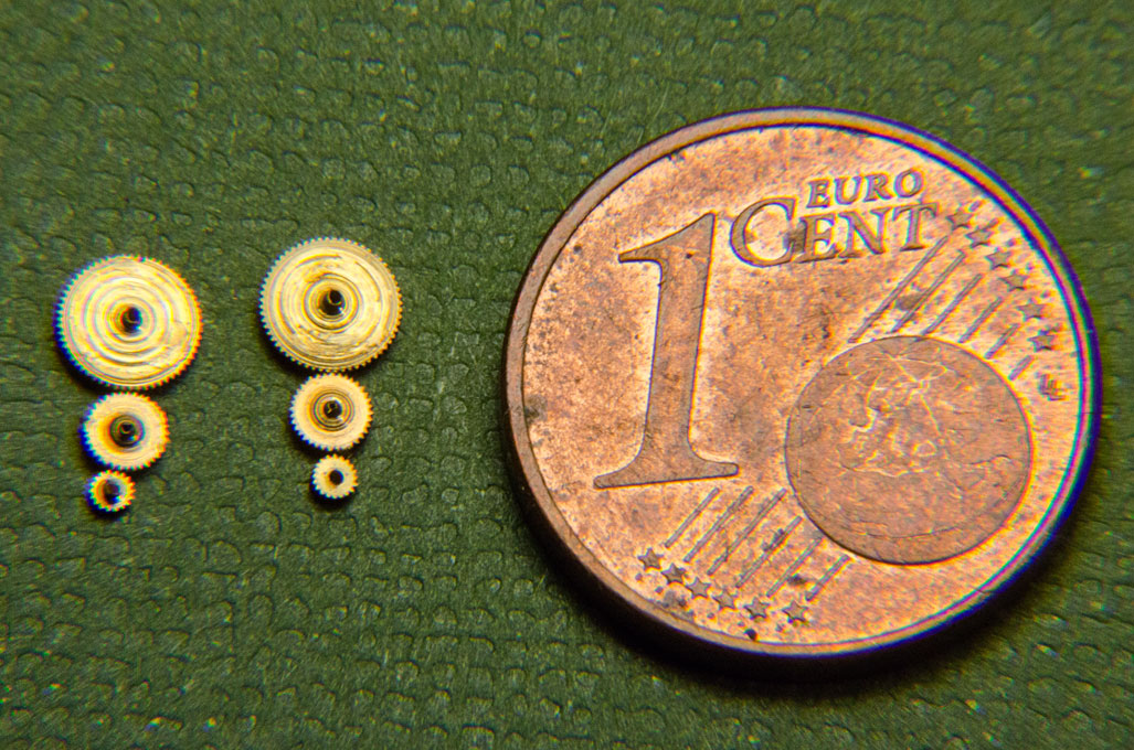
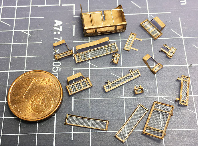 The collection of gratings and steps
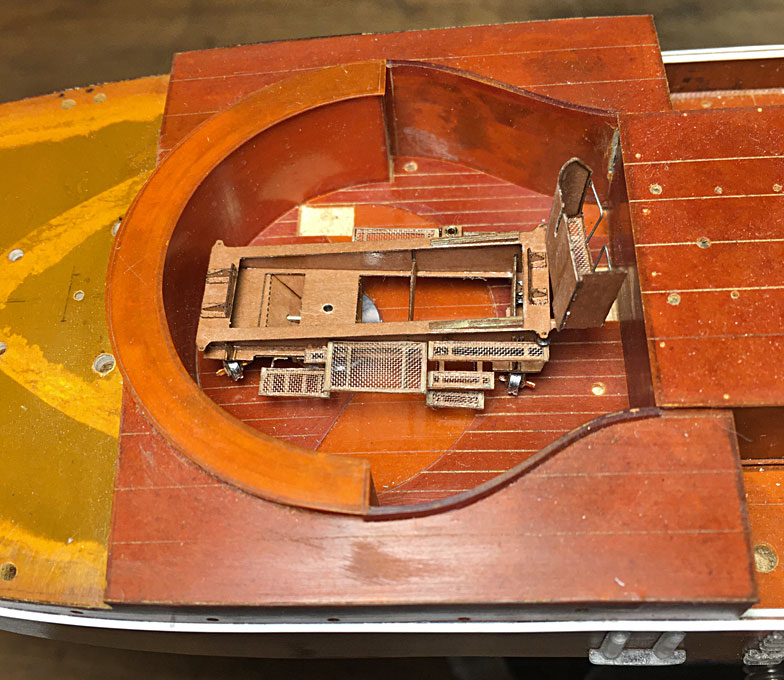
I am not entirely happy with the result and tend to think, that etched parts may have looked finer. But then their assembly would have required a lot of very delicate soldering work � I don�t trust CA for metal/metal bonds too much. On the other hand, attaching the gratings to the lower carriage frame is likely to be easier for the cardboard parts than for brass parts. Before that can be done, I need to add the wheels, which requires a lot of handling ...
To be continued ...


