I ordered a bottle of the dye - 2 ounces for about US$30 on Amazon. But it has to be diluted with water or alcohol so it makes 2 quarts. So it is about the price of two bottles of good wine. It better be worth it!
****
The "wire" in the CAD model anchor chain is 0.6615 mm diameter and a circular cross section. The printed parts are oval in cross section, 0.62 to 0.65 mm on the vertical and 0.71 to 0.74 mm on the horizontal. So I am getting about a 2% to 10% reduction in the width on the film, but an additional 10% to 12 % thickness on the vertical.
I sort of expected the parts to be a bit too thick on the vertical dimension. From my experience with the ventilator grills I knew that the very thin parts are translucent so additional resin gets cured on the upper surfaces of very thin parts.
But I can't explain why the parts were thin on the horizontal dimension. I would expect resin to be cured over the entire pixel width but this apparently is not happening.
Increasing the exposure time probably would increase the horizontal width, but it might also cure more resin in the vertical dimension. Increasing the step size would reduce the total exposure time, and perhaps reduce the vertical thickness.
I am happy with the results I got - no one is going to be taking a micrometer to the chain on the model. But I might try printing them again with a different step size and exposure time.
With a model diameter of 0.66 mm the 0.02mm step size gave 33 slices and exposures. A 0.03 mm step size would give 22 slices, 0.04 mm would give 16 and 0.05 mm would give 13 slices.
So I might try the 0.04 mm step size to halve the number of exposures and try to reduce the vertical diameter, but use an exposure time of 3 seconds to expand the horizontal width a bit.
****
The reason I want to control the printing better to get a circular cross section is that there are many yards/meters of life rails on the model. They real parts were made of pipe 1.25", 1" and 0.75" diameter. At 1:96 this comes out to 0.013", 0.010 and 0.008", or 0.33 mm, 0.25 mm and 0.20 mm. This is less than half the chain link "wire" diameter.
I have successfully printed 0.20 mm diameter pieces, but they are extremely fragile. I really don't want the parts to come out any smaller, but 10% oversize would be OK. But I want them reasonably close to cylindrical.
I have been reading up on some of the flexible resins. I would think these would be less susceptible to the accidental bumps that happen while assembling models. But several sites say they are not suitable for thin walls, and the minimum thickness should be 1 mm, or 125 times the thickness of the smallest pipes!
Furthermore, because they are flexible they may not separate from the plastic film evenly and become bent while printing. This is also probably true for regular resins, so lots of supports will be needed!
Phil
3D printing
Moderators: MartinJQuinn, JIM BAUMANN, HMAS, Tiny69, Dave Wooley
-
DrPR

- Posts: 1691
- Joined: Sun Mar 07, 2010 12:01 am
- Location: Corvallis, Oregon, USA
- Contact:
Re: 3D printing
A collision at sea will ruin your entire day. Aristotle
-
wefalck

- Posts: 2126
- Joined: Wed Sep 28, 2011 12:04 pm
- Location: Paris
- Contact:
Re: 3D printing
Tom, good to see another geochemist here  My knowledge of resin chemistry is rather limited, but in such cases I try to understand what happens, which helps to predict what might happen or to explain failures ...
My knowledge of resin chemistry is rather limited, but in such cases I try to understand what happens, which helps to predict what might happen or to explain failures ...Eberhard
Former chairman Arbeitskreis historischer Schiffbau e.V. (German Association for Shipbuilding History)
--------------------------------------------------------------------------------------------------------------------------------------------------------------------------------------------




Former chairman Arbeitskreis historischer Schiffbau e.V. (German Association for Shipbuilding History)
--------------------------------------------------------------------------------------------------------------------------------------------------------------------------------------------
-
Fliger747
- Posts: 5068
- Joined: Wed Jan 02, 2013 1:15 am
Re: 3D printing
I suppose that without access to an electron microscope we are just as well informed as to the practical result by seeing whether of not the dye forms just a surface coating or shows signs of surface penetration and if either phenomenon has a satisfactory appearance on the model.
I may replace the chains on either Missouri or Alaska and the dye coloring might be a useful approach? I am still quite impressed by the hand constructed chains of EJ Foeth and Song!
I fully expect advancements in equipment technology and resins in the future. Certainly many items can currently be printed that lack the strength to be realized as useful pieces on a model. Advancements in this technology are driven by industrial and medical applications and we are the grateful benefactors.
Regards: Tom
I may replace the chains on either Missouri or Alaska and the dye coloring might be a useful approach? I am still quite impressed by the hand constructed chains of EJ Foeth and Song!
I fully expect advancements in equipment technology and resins in the future. Certainly many items can currently be printed that lack the strength to be realized as useful pieces on a model. Advancements in this technology are driven by industrial and medical applications and we are the grateful benefactors.
Regards: Tom
-
Iceman 29

- Posts: 1945
- Joined: Tue Sep 29, 2020 4:35 pm
- Location: Bretagne, France
Re: 3D printing
You can also make a mixture of "hard" resin and flex resin. This allows to obtain a more flexible object according to the dosage.I have been reading up on some of the flexible resins. I would think these would be less susceptible to the accidental bumps that happen while assembling models. But several sites say they are not suitable for thin walls, and the minimum thickness should be 1 mm, or 125 times the thickness of the smallest pipes!
For my part, with the standard resin, for small pieces or railing, I do not pass them to UV after printing, I leave them like that, a little to the light of the workshop, then I paint them to protect them from UV.
It stays flexible.
For the big parts, I UV them a little bit ( 1 or 2 mn ) to be able to sand them more easily if necessary; the hulls for example, as soon as it's not sticky anymore, I stop the UV.
Pascal
�Battleship Bretagne 3D: https://vu.fr/FvCY
�SS Delphine 3D: https://vu.fr/NeuO
�SS Nomadic 3D: https://vu.fr/tAyL
�USS Nokomis 3D: https://vu.fr/kntC
�USS Pamanset 3D: https://vu.fr/jXGQ
�Battleship Bretagne 3D: https://vu.fr/FvCY
�SS Delphine 3D: https://vu.fr/NeuO
�SS Nomadic 3D: https://vu.fr/tAyL
�USS Nokomis 3D: https://vu.fr/kntC
�USS Pamanset 3D: https://vu.fr/jXGQ
-
Collector#1

- Posts: 33
- Joined: Mon Nov 09, 2020 7:57 am
- Location: Wetter, NRW, Germany
Re: 3D printing
I tried to use ABS like resin, but it does not work (see comparision picture below).
Also I skipped UV curing and might do it at the end before painting. This saves my details while cutting off the supports.
Also I skipped UV curing and might do it at the end before painting. This saves my details while cutting off the supports.
- Attachments
-
-
DrPR
- Posts: 1691
- Joined: Sun Mar 07, 2010 12:01 am
- Location: Corvallis, Oregon, USA
- Contact:
Re: 3D printing
I ran the chain prints again, using a 0.04 mm step size and 3 second exposure (as opposed to the earlier 0.02 mm step and 2 second exposure). Half as many exposures but 50% longer exposure time.
The design diameter of the chain "wire" was 0.66 mm. The horizontal links came out 0.75 mm to 0.84 mm thick, 14% to 27% oversized. The vertical links were 0.63 mm to 0.66 mm, or 95% under size to 100%.
Most of the links were free or slightly fused, but when I gently twisted the chain around the long axis almost all of them separated. So this was near the limit for getting a flexible chain. However, I printed 3 chains and one didn't print completely - no idea why.
I think the 2 second exposure was better because it have thinner vertical layers - even though I was printing layers twice as thick as before, so only half the number of exposures. I can see no visible difference in the surfaces of the 0.02 mm vertical step and 0.04 mm step parts, so 0.04 mm is adequate. Actually, these things are so small that if there was a difference it wouldn't be noticeable.
There really wasn't much difference in the thickness of the vertical links between the two runs, so the longer exposure time made no difference there. But it certainly did make the horizontal link thickness greater even though there were only half the number of exposures. And that was causing the links to fuse.
So it looks like the optimal settings for these tiny parts 1s about 0.04 mm step size and 2 second exposures with the Anycubic Basic Grey Resin - which they call "Colored UV Resin" on their web site - on the Photon Mono printer.
Phil
PS: C4, I have been separating the parts from the supports before curing. This seems to work better because the cured resin is a lot more brittle and tends to leave more pock marks and stubs on the surfaces of the parts than with the uncured resin.
The design diameter of the chain "wire" was 0.66 mm. The horizontal links came out 0.75 mm to 0.84 mm thick, 14% to 27% oversized. The vertical links were 0.63 mm to 0.66 mm, or 95% under size to 100%.
Most of the links were free or slightly fused, but when I gently twisted the chain around the long axis almost all of them separated. So this was near the limit for getting a flexible chain. However, I printed 3 chains and one didn't print completely - no idea why.
I think the 2 second exposure was better because it have thinner vertical layers - even though I was printing layers twice as thick as before, so only half the number of exposures. I can see no visible difference in the surfaces of the 0.02 mm vertical step and 0.04 mm step parts, so 0.04 mm is adequate. Actually, these things are so small that if there was a difference it wouldn't be noticeable.
There really wasn't much difference in the thickness of the vertical links between the two runs, so the longer exposure time made no difference there. But it certainly did make the horizontal link thickness greater even though there were only half the number of exposures. And that was causing the links to fuse.
So it looks like the optimal settings for these tiny parts 1s about 0.04 mm step size and 2 second exposures with the Anycubic Basic Grey Resin - which they call "Colored UV Resin" on their web site - on the Photon Mono printer.
Phil
PS: C4, I have been separating the parts from the supports before curing. This seems to work better because the cured resin is a lot more brittle and tends to leave more pock marks and stubs on the surfaces of the parts than with the uncured resin.
A collision at sea will ruin your entire day. Aristotle
-
Iceman 29
- Posts: 1945
- Joined: Tue Sep 29, 2020 4:35 pm
- Location: Bretagne, France
Re: 3D printing
Always remember to filter the resin if there are printing defects such as pieces that did not print completely. Small pieces of very hard resin may have fallen to the bottom of the tray onto the FEP film, and when printing the first layers of the next and subsequent pieces, the aluminum tray may crush these small pieces onto the film and puncture it. In the worst case, a leak may occur and damage the screen, or crack it.
Pascal
�Battleship Bretagne 3D: https://vu.fr/FvCY
�SS Delphine 3D: https://vu.fr/NeuO
�SS Nomadic 3D: https://vu.fr/tAyL
�USS Nokomis 3D: https://vu.fr/kntC
�USS Pamanset 3D: https://vu.fr/jXGQ
�Battleship Bretagne 3D: https://vu.fr/FvCY
�SS Delphine 3D: https://vu.fr/NeuO
�SS Nomadic 3D: https://vu.fr/tAyL
�USS Nokomis 3D: https://vu.fr/kntC
�USS Pamanset 3D: https://vu.fr/jXGQ
-
Fliger747
- Posts: 5068
- Joined: Wed Jan 02, 2013 1:15 am
Re: 3D printing
A thought for railings: Printing the rails at an angle other than level may reduce the leaving that often can occur in horizontal rails. I have had very much better results with the rather thin 20 mm Orlikon barrels. Worth a try!
Tom
Tom
-
DrPR
- Posts: 1691
- Joined: Sun Mar 07, 2010 12:01 am
- Location: Corvallis, Oregon, USA
- Contact:
Re: 3D printing
Pascal,
That thought enters my mind frequently! I always look for missing pieces and try to account for them.
Tom,
That is an excellent suggestion, and definitely something to keep in mind with flexible resins.
If I printed railings horizontal the entire length of a pipe would be printed in each pass, and that would maximize the forces for removing them from the plastic film. Printing at an angle would reduce the print contact size greatly, and that would minimize the separation forces. Furthermore, with flexible resins it should minimize the deformation of the rails.
45 degrees from horizontal would reduce the surface area and procedure the smallest jaggies. And it should minimize the cross section distortion due to step size/slice count and exposure times.
Phil
That thought enters my mind frequently! I always look for missing pieces and try to account for them.
Tom,
That is an excellent suggestion, and definitely something to keep in mind with flexible resins.
If I printed railings horizontal the entire length of a pipe would be printed in each pass, and that would maximize the forces for removing them from the plastic film. Printing at an angle would reduce the print contact size greatly, and that would minimize the separation forces. Furthermore, with flexible resins it should minimize the deformation of the rails.
45 degrees from horizontal would reduce the surface area and procedure the smallest jaggies. And it should minimize the cross section distortion due to step size/slice count and exposure times.
Phil
A collision at sea will ruin your entire day. Aristotle
-
Fliger747
- Posts: 5068
- Joined: Wed Jan 02, 2013 1:15 am
Re: 3D printing
Phil:
I think a lot less than 45 degrees should work OK, with the Orlikon barrels even 10 deg was enough to make for a fairly small printing patch.
Good luck! Tom
I think a lot less than 45 degrees should work OK, with the Orlikon barrels even 10 deg was enough to make for a fairly small printing patch.
Good luck! Tom
-
wefalck
- Posts: 2126
- Joined: Wed Sep 28, 2011 12:04 pm
- Location: Paris
- Contact:
Re: 3D printing
Is it really worthwhile printing the whole rail and not just the stanchions? Even, if the holes partly close, one would have dimples to guide the drilling. One could also print a drilling jig to hold the stanchions during that operation.
Eberhard
Former chairman Arbeitskreis historischer Schiffbau e.V. (German Association for Shipbuilding History)
--------------------------------------------------------------------------------------------------------------------------------------------------------------------------------------------
Former chairman Arbeitskreis historischer Schiffbau e.V. (German Association for Shipbuilding History)
--------------------------------------------------------------------------------------------------------------------------------------------------------------------------------------------
-
BB62vet

- Posts: 3162
- Joined: Mon Nov 18, 2013 3:41 pm
- Location: Mocksville, NC
Re: 3D printing
I disagree completely with this reply. The whole point of 3D printing is just that - printing the parts rather than scratchbuilding them by hand or another method. We've already established that this can be done - the question is - how to get the best result and adjusting our methods in order to achieve that goal. Trying to come up with some sort of drilling jig is (IMHO) a waste of time & energy to what end? More unnecessary work. As an example, I did just about this very thing with the main deck handrails/stanchions on my LSM/R project using the kit stanchions and black thread for the rails. Too late now, but I should have followed thru with making the entire affair by 3D design/printing. Anyhow, that's my take on this approach.wefalck wrote:Is it really worthwhile printing the whole rail and not just the stanchions? Even, if the holes partly close, one would have dimples to guide the drilling. One could also print a drilling jig to hold the stanchions during that operation.
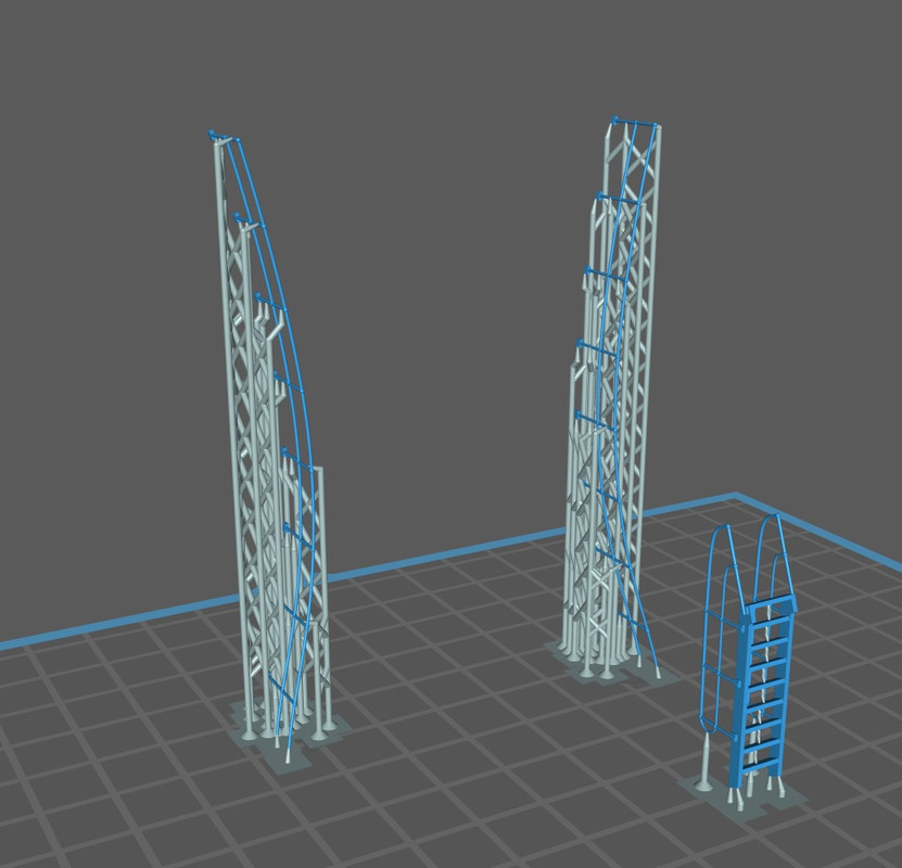
I just printed 3 different sets of handrails oriented flat on the printing platen - they came out fair - not great, not totally unusable - but, could be better. So, I'm going back and re-orient these parts at a 15 deg. angle to the platen and see what results I get. Here's a picture of what two of these three sets should look like:
Hank
HMS III
Mocksville, NC
BB62 vet 68-69
Builder's yard:
USS STODDARD (DD-566) 66-68 1:144, Various Lg Scale FC Directors
Finished:
USS NEW JERSEY (BB-62) 67-69 1:200
USN Sloop/Ship PEACOCK (1813) 1:48
ROYAL CAROLINE (1748) 1:47
AVS (1768) 1:48
Mocksville, NC
BB62 vet 68-69
Builder's yard:
USS STODDARD (DD-566) 66-68 1:144, Various Lg Scale FC Directors
Finished:
USS NEW JERSEY (BB-62) 67-69 1:200
USN Sloop/Ship PEACOCK (1813) 1:48
ROYAL CAROLINE (1748) 1:47
AVS (1768) 1:48
-
Iceman 29
- Posts: 1945
- Joined: Tue Sep 29, 2020 4:35 pm
- Location: Bretagne, France
Re: 3D printing
The problem is to avoid wandering on the horizontal bars, and to remove the traces from the supports. But with the Dremel, turning at maximum speed, you can do it well.
The ideal is to print vertically on the railing but it takes more time and it is not always possible because of the shape.
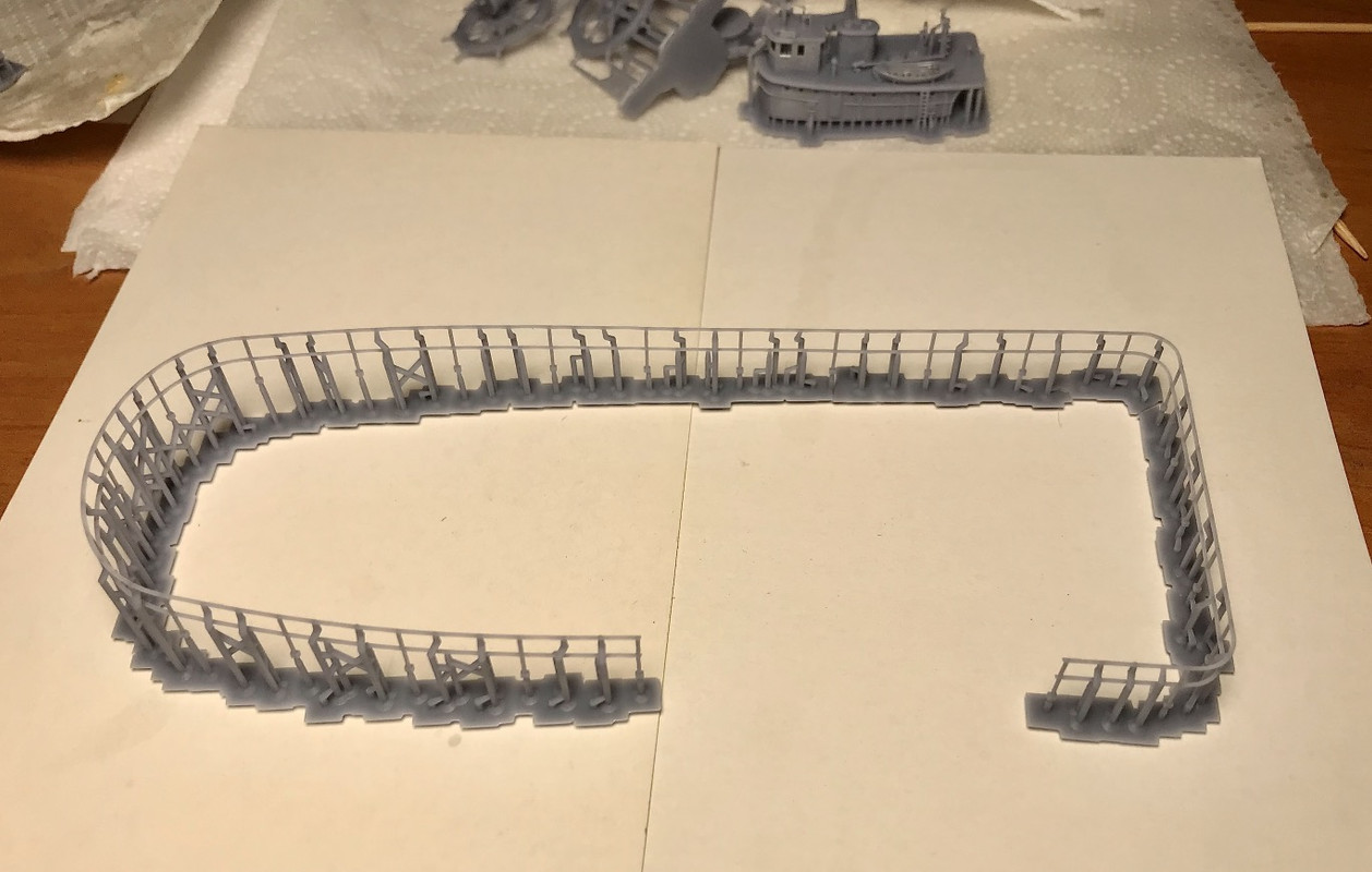
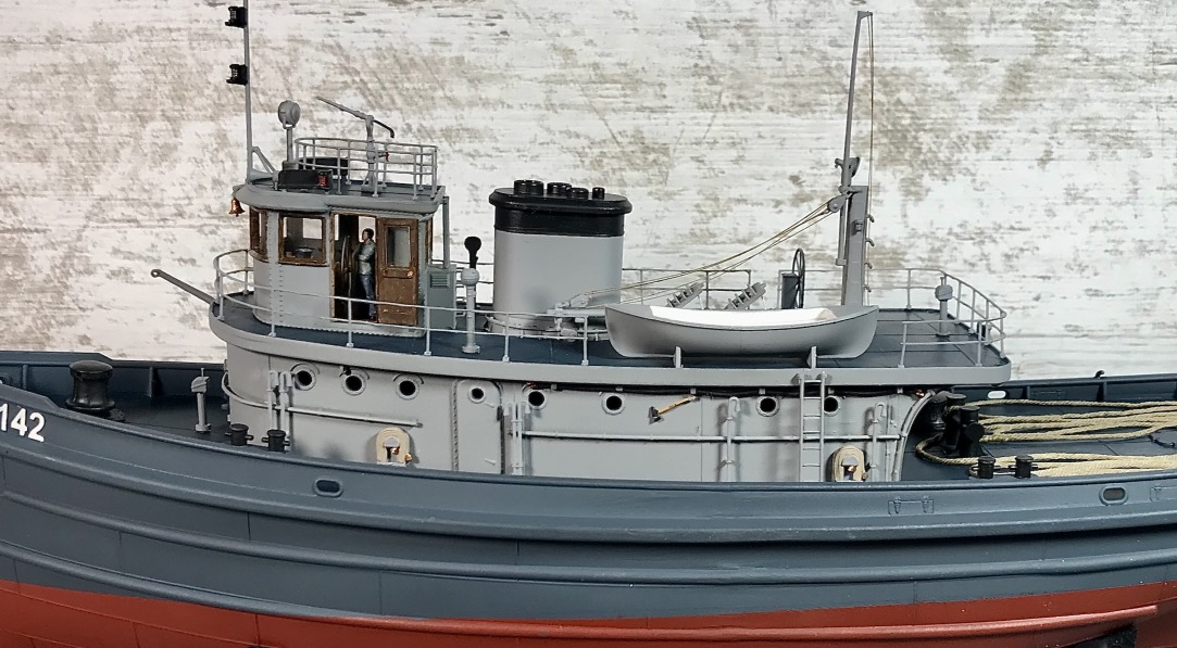
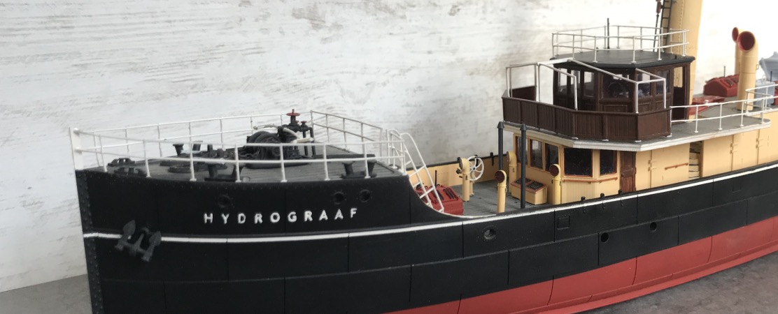
Railing printed Horizontaly, the result was not so good.
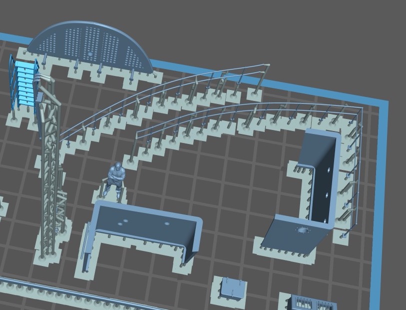
Vertical printing gives better results, just divide the railing in several parts.
The ideal is to print vertically on the railing but it takes more time and it is not always possible because of the shape.
Railing printed Horizontaly, the result was not so good.
Vertical printing gives better results, just divide the railing in several parts.
Pascal
�Battleship Bretagne 3D: https://vu.fr/FvCY
�SS Delphine 3D: https://vu.fr/NeuO
�SS Nomadic 3D: https://vu.fr/tAyL
�USS Nokomis 3D: https://vu.fr/kntC
�USS Pamanset 3D: https://vu.fr/jXGQ
�Battleship Bretagne 3D: https://vu.fr/FvCY
�SS Delphine 3D: https://vu.fr/NeuO
�SS Nomadic 3D: https://vu.fr/tAyL
�USS Nokomis 3D: https://vu.fr/kntC
�USS Pamanset 3D: https://vu.fr/jXGQ
-
wefalck
- Posts: 2126
- Joined: Wed Sep 28, 2011 12:04 pm
- Location: Paris
- Contact:
Re: 3D printing
I gather it is all a matter of the scale you are working at. When it comes to bars 0.2 mm or less in diameter, my understanding is that the current printing technology gets to its limits.
I don't really like the term 'scratch-building' - I make parts that eventually will fit together to make a model. Of course, I work from scratch, using the tools and techniques available to me. 3D-printing could be one of those techniques that I would find useful to create complex structures with curved surfaces or small parts that would be difficult to machine. So 3D-printing for me is another tool in my box, not a tool that replaces all other tools. I gather that would rather boring.
I don't really like the term 'scratch-building' - I make parts that eventually will fit together to make a model. Of course, I work from scratch, using the tools and techniques available to me. 3D-printing could be one of those techniques that I would find useful to create complex structures with curved surfaces or small parts that would be difficult to machine. So 3D-printing for me is another tool in my box, not a tool that replaces all other tools. I gather that would rather boring.
Eberhard
Former chairman Arbeitskreis historischer Schiffbau e.V. (German Association for Shipbuilding History)
--------------------------------------------------------------------------------------------------------------------------------------------------------------------------------------------
Former chairman Arbeitskreis historischer Schiffbau e.V. (German Association for Shipbuilding History)
--------------------------------------------------------------------------------------------------------------------------------------------------------------------------------------------
-
BB62vet
- Posts: 3162
- Joined: Mon Nov 18, 2013 3:41 pm
- Location: Mocksville, NC
Re: 3D printing
On your first comment - 0.2mm is getting pretty small and hard to print correctly, esp. when it comes to railings, etc. Currently for my 1:144 scale builds I've found that stanchions at 0.30mm dia. will come out nicely, handrails NLT 0.26mm dia. and that's getting rather finite. I have however, successfully printed much smaller diameter details that were a complete surprise to me that they even printed. As has been stated several times before - the type of resin and the orientation & support of the parts play an integral part of successful 3D parts production.wefalck wrote:I gather it is all a matter of the scale you are working at. When it comes to bars 0.2 mm or less in diameter, my understanding is that the current printing technology gets to its limits.
I don't really like the term 'scratch-building' - I make parts that eventually will fit together to make a model. Of course, I work from scratch, using the tools and techniques available to me. 3D-printing could be one of those techniques that I would find useful to create complex structures with curved surfaces or small parts that would be difficult to machine. So 3D-printing for me is another tool in my box, not a tool that replaces all other tools. I gather that would rather boring.
On your second comment I agree - the 3D design/printing is an addition to the toolbox for the modeler and is not a wholesale replacement for older tried & true methods for model making. I will give myself 25 self-inflicted lashes as a result of my failure to communicate properly.

Hank
HMS III
Mocksville, NC
BB62 vet 68-69
Builder's yard:
USS STODDARD (DD-566) 66-68 1:144, Various Lg Scale FC Directors
Finished:
USS NEW JERSEY (BB-62) 67-69 1:200
USN Sloop/Ship PEACOCK (1813) 1:48
ROYAL CAROLINE (1748) 1:47
AVS (1768) 1:48
Mocksville, NC
BB62 vet 68-69
Builder's yard:
USS STODDARD (DD-566) 66-68 1:144, Various Lg Scale FC Directors
Finished:
USS NEW JERSEY (BB-62) 67-69 1:200
USN Sloop/Ship PEACOCK (1813) 1:48
ROYAL CAROLINE (1748) 1:47
AVS (1768) 1:48
-
DrPR
- Posts: 1691
- Joined: Sun Mar 07, 2010 12:01 am
- Location: Corvallis, Oregon, USA
- Contact:
Re: 3D printing
The resolution of the LCD display is a key factor in determining the minimum X/Y (horizontal) width.
I have printed 0.10 mm parts on the Photon Mono with a 0.05 mm pixels, but the results are pretty rough. Don't look too closely. After all, the parts are only two pixels wide, and if there is any curvature the width varies greatly along the length of the part.
But I have found that 0.15 mm is a usable width for thin vertical details, especially since the vertical resolution can be a little as 0.01 mm.
Some of the new printers have much smaller pixel sizes, so it should be possible to print finer details.
****
I can't drill many #80 holes (0.0135" or 0.34 mm) by hand with a bit before I break it. Maybe 10 if I am lucky. With 500 stanchions with 3 holes each that's 1500 holes, or 150 bits. AT $8.95 for six bits (MicroMark) that's $223.75 without postage.
For this type of work you need a milling machine with very little runout on the spindle. I don't have one, but I am thinking of getting one of the Sherline mills. I have a number of parts where the steps and railings could be made with 0.008", 0.010" and 0.012" brass wire and I would need tiny (#80) holes for these pieces to insert into (with a bit of epoxy to hold them in place and fill the hole around the wire. And these holes will need to be positioned precisely, which I cannot do repeatedly by hand.
I have also considered making the railings by cutting lengths of brass wire of appropriate diameter and soldering them together. This is probably the most practical method, and I have more than half a century experience soldering tiny parts. For this I will need a jig to hold the pieces in place, and printing one is a very good idea.
Phil
I have printed 0.10 mm parts on the Photon Mono with a 0.05 mm pixels, but the results are pretty rough. Don't look too closely. After all, the parts are only two pixels wide, and if there is any curvature the width varies greatly along the length of the part.
But I have found that 0.15 mm is a usable width for thin vertical details, especially since the vertical resolution can be a little as 0.01 mm.
Some of the new printers have much smaller pixel sizes, so it should be possible to print finer details.
****
I can't drill many #80 holes (0.0135" or 0.34 mm) by hand with a bit before I break it. Maybe 10 if I am lucky. With 500 stanchions with 3 holes each that's 1500 holes, or 150 bits. AT $8.95 for six bits (MicroMark) that's $223.75 without postage.
For this type of work you need a milling machine with very little runout on the spindle. I don't have one, but I am thinking of getting one of the Sherline mills. I have a number of parts where the steps and railings could be made with 0.008", 0.010" and 0.012" brass wire and I would need tiny (#80) holes for these pieces to insert into (with a bit of epoxy to hold them in place and fill the hole around the wire. And these holes will need to be positioned precisely, which I cannot do repeatedly by hand.
I have also considered making the railings by cutting lengths of brass wire of appropriate diameter and soldering them together. This is probably the most practical method, and I have more than half a century experience soldering tiny parts. For this I will need a jig to hold the pieces in place, and printing one is a very good idea.
Phil
A collision at sea will ruin your entire day. Aristotle
-
Fliger747
- Posts: 5068
- Joined: Wed Jan 02, 2013 1:15 am
Re: 3D printing
Phil:
If you aren't happy with printed rails (Pascal's look pretty good in 1:100) perhaps you can try printing stanchions and feed a stretched sprue rail through them. I was able to use printed stanchions and use variously sprue or thread for wire type lifelines with a very light and airy (you can hardly see them) result. Making a clean hole might be difficult but the hole will act as a pilot. Possibly doing some experimentation for such a major project will yield valid comparisons with competing methods in your scale.
Good Luck! Tom
If you aren't happy with printed rails (Pascal's look pretty good in 1:100) perhaps you can try printing stanchions and feed a stretched sprue rail through them. I was able to use printed stanchions and use variously sprue or thread for wire type lifelines with a very light and airy (you can hardly see them) result. Making a clean hole might be difficult but the hole will act as a pilot. Possibly doing some experimentation for such a major project will yield valid comparisons with competing methods in your scale.
Good Luck! Tom
-
wefalck
- Posts: 2126
- Joined: Wed Sep 28, 2011 12:04 pm
- Location: Paris
- Contact:
Re: 3D printing
That's what I suggested above, actually ...
Eberhard
Former chairman Arbeitskreis historischer Schiffbau e.V. (German Association for Shipbuilding History)
--------------------------------------------------------------------------------------------------------------------------------------------------------------------------------------------
Former chairman Arbeitskreis historischer Schiffbau e.V. (German Association for Shipbuilding History)
--------------------------------------------------------------------------------------------------------------------------------------------------------------------------------------------
-
Fliger747
- Posts: 5068
- Joined: Wed Jan 02, 2013 1:15 am
Re: 3D printing
My humble opinion (Wild az guess) is that some compromise is necessary, increasing with the cube of the diminution in scale. Part of the issue with perforated stanchions is the extreme fragility at the point of penetration. Addition of the smallest possible amount of glue at these points will help a lot. For my ARL I printed the stanchions with small hooks to rest the sprue or thread on and maintain the appropriate spacing of the lifelines. This is appropriate for wire type lifelines but not as suitable for piperail. I used small square pads on the foot as did Pascal on his research vessel and tug. The overall effect is quite good if not fully prototypical. Another tactic used by Hank includes the 3" lip on the bottom. I supplied a circular rail for Hank for his 3"50 director platform for Stoddard that includes the whole deck side which has an overhang. One could drill all the holes for the stanchions, I did this for much of the rail on the APA, with brass wire stanchions. I made a guide block to assure the stanchions were vertical and trimmed to exact length. One could make printed stanchions with a slight lip at deck level, this would at least eliminate the foot pads.
Pipe rails often have corner bends with the stanchions at other points, easiest to replicate by printing.
Tom
Pipe rails often have corner bends with the stanchions at other points, easiest to replicate by printing.
Tom
-
DrPR
- Posts: 1691
- Joined: Sun Mar 07, 2010 12:01 am
- Location: Corvallis, Oregon, USA
- Contact:
Re: 3D printing
I have been experimenting with a number of things, including the Mk 37 director on the Okie Boat.
I printed it in three parts as shown here, the main shell, the antenna support and the dish antenna, with a US one cent piece for size reference. The supports for the antenna support "spider" were too complex to integrate with the supports for the other parts.
Here are the parts temporarily assembled"
It looks pretty good, but the thin hand/foot rails on the sides of the director caused a lot of grief. These are only 0.392 mm (0.015 inch) diameter and quite fragile.
The default Chitubox settings added a lot of supports to these rails, and it proved to be almost impossible to separate the supports from the rails without breaking the rails. However, it turns out that the rails will print without any supports - but not without another problem.
The arrows point to places where the rails sagged while printing, probably due to the separation forces while lifting the print from the plastic film at the bottom of the resin vat. The rails are the correct width horizontally, as can be seen in the first picture above. But they sag between the brackets that attach them to the sides of the director shell, and are about twice the correct thickness vertically in places.
This and similar problems with other pieces makes me think it would be best to print the mounting brackets and then attach the appropriate diameter brass wire for the rails.
I also see a common problem when printing hollow parts (this was hollowed using the Chitubox "Hollow" function with a 2 mm wall thickness). The resin shrinks a bit when curing causing the sides of the director shell to bow inward. You can see the outline of the 2mm thick top where the arrows point.
I had another problem in the first attempt to print the director shell and the barbette it rests on. I used the default Chitobox supports and the surfaces closest to the print platform were wavy and not flat as they should be. Others have reported a similar problem. The cause was not enough supports. The solution was to add the supports manually and place as many as possible.
This isn't the greatest photo but you can see the dense "forest" of supports that were necessary to get a smooth bottom surface. The supports were placed at about 3 mm (0.1 inch) spacing.
The antenna support structure "spider" printed very nicely.
Even the tiniest details like nuts and bolts printed, but they are hard to see in these pictures. The very thin wave guide and cables running from the back of the director to the radar assembly at the back of the dish antenna came out perfectly. And if you look closely on the right side behind the antenna dish you can see the support for an alignment telescope, including the thumb screws to fasten the telescope in place.
The dish is parabolic on the front side and conical on the back. It is very thin (0.12 mm or 0.005 inch) near the edge. As you can see, in one place there is a tiny hole. Two out of three that I printed had holes. However I think these will fill in OK when the parts are panted.
Phil
Here are the parts temporarily assembled"
The default Chitubox settings added a lot of supports to these rails, and it proved to be almost impossible to separate the supports from the rails without breaking the rails. However, it turns out that the rails will print without any supports - but not without another problem.
This and similar problems with other pieces makes me think it would be best to print the mounting brackets and then attach the appropriate diameter brass wire for the rails.
I also see a common problem when printing hollow parts (this was hollowed using the Chitubox "Hollow" function with a 2 mm wall thickness). The resin shrinks a bit when curing causing the sides of the director shell to bow inward. You can see the outline of the 2mm thick top where the arrows point.
I had another problem in the first attempt to print the director shell and the barbette it rests on. I used the default Chitobox supports and the surfaces closest to the print platform were wavy and not flat as they should be. Others have reported a similar problem. The cause was not enough supports. The solution was to add the supports manually and place as many as possible.
The antenna support structure "spider" printed very nicely.
The dish is parabolic on the front side and conical on the back. It is very thin (0.12 mm or 0.005 inch) near the edge. As you can see, in one place there is a tiny hole. Two out of three that I printed had holes. However I think these will fill in OK when the parts are panted.
Phil
A collision at sea will ruin your entire day. Aristotle