Page 2 of 21
Re: 1:160 S.M.S. WESPE Armoured Gunboat (1876)
Posted: Thu Jan 22, 2015 3:13 pm
by wefalck
Thanks, Jim. Your praise is much appreciated � trying to live up to it

*************
Engine-room skylight
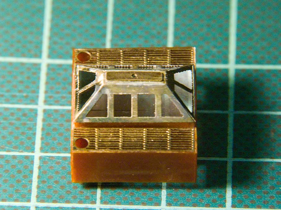
The frame of the engine room skylight consists of a an etched brass part, folded up and soldered together. On the inside, grooves have been etched that will serve to locate the protective bars to made from thin copper wire. The lower frame was constructed from Pertinax. The �wooden� gratings on both sides of the lower frame are again etched parts.
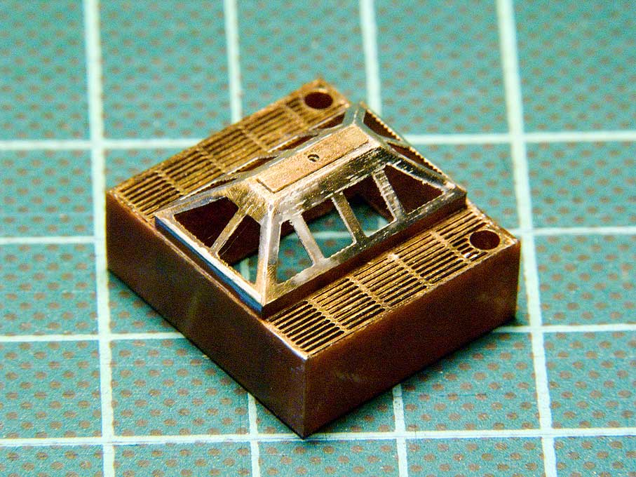 Unglazed framework for the engine-room skylight
Once this structure was complete, a square block of the size of the footprint of the skylight was milled from a piece of Plexiglas.
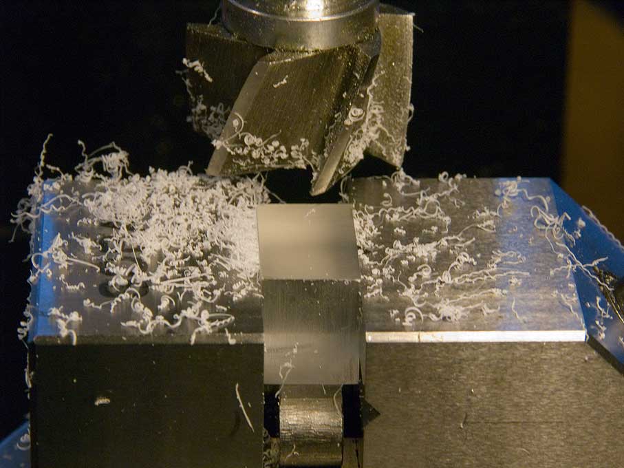 Squaring up a Plexiglas block for the skylight
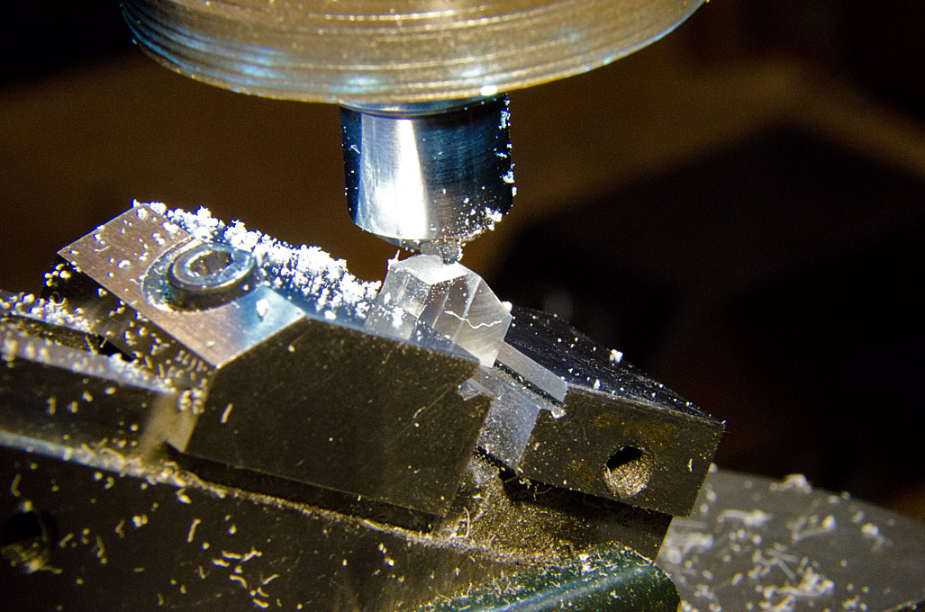
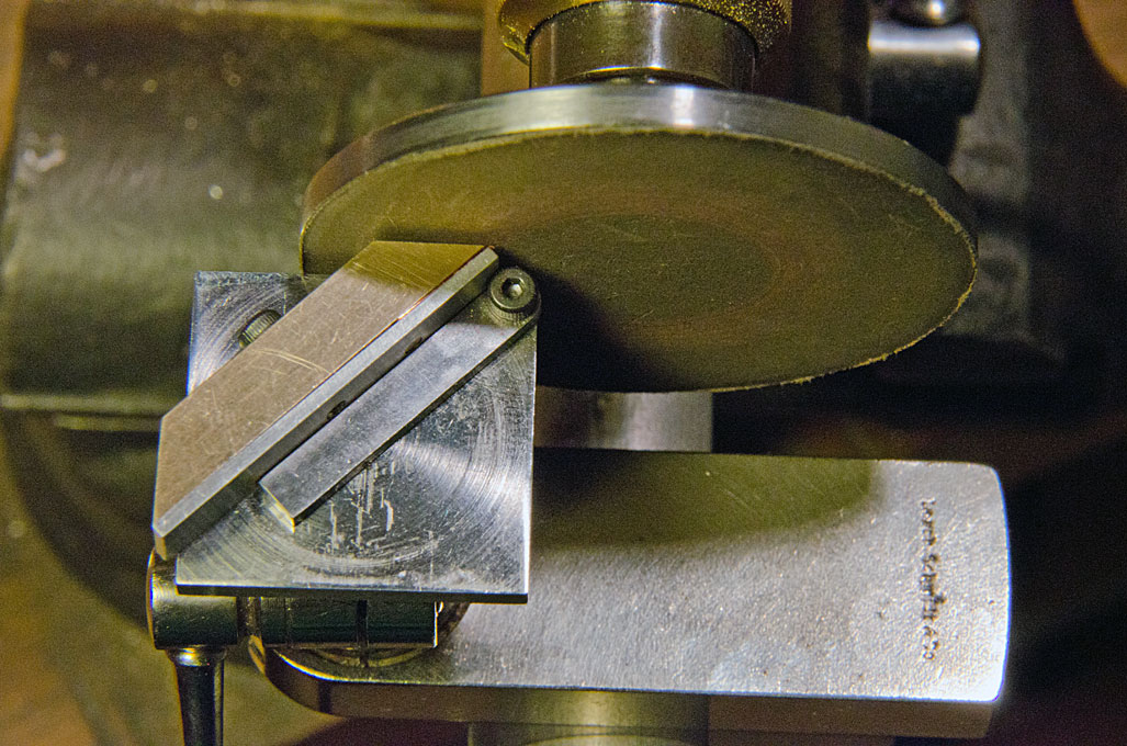
In the next step the roof-shaped faces were milled on. To this end, a small insert vice was set to the appropriate angle of 40� in a larger vice bolted to the mill table. The fixed jaw of the insert vice pointed upward and the side of the block to be milled rested against it. This ensured that all four inclined faces would have the same angle and would start from the same height with respect to the reference (bottom) face of the block.
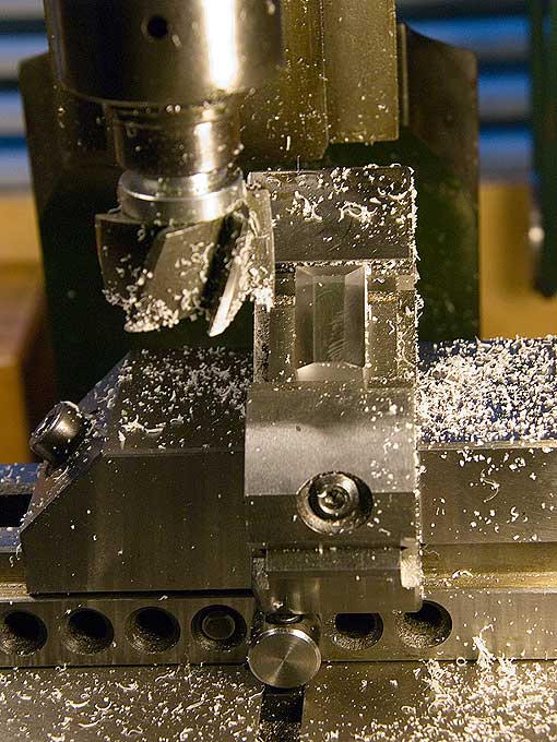 Milling the sloping faces
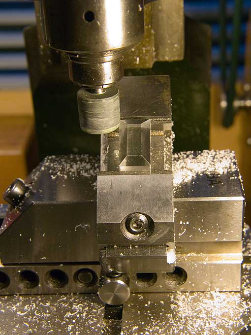 Polishing the sloping faces
A very smooth surface with little tool marks can be achieved on Plexiglas. The final polishing of the surfaces was done using CRATEX-type drum polishers followed by a felt drum loaded with polishing paste. All in the same vice setting to ensure a flat surface. I was lucky the Plexiglas 'house' fitted like a plug into the skylight frame.
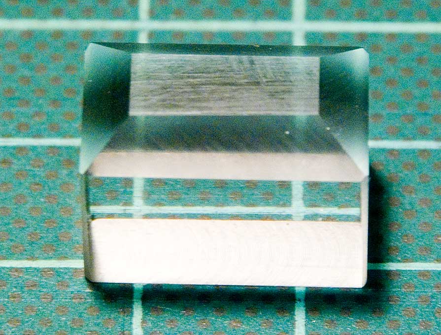 Finished Plexiglas 'glazing' block
 Glazed engine room skylight
To be continued ...
Re: 1:160 S.M.S. WESPE Armoured Gunboat (1876)
Posted: Thu Jan 22, 2015 6:16 pm
by PICKETBOAT
wefalck
Stunning workmanship. Beautifully engineered.
Re: 1:160 S.M.S. WESPE Armoured Gunboat (1876)
Posted: Sun Feb 01, 2015 10:39 am
by wefalck
Thanks indeed
************
The 30.5 cm Rk/l22 gun
The main armament of the WESPE-Class was a massive 30.5 cm (12�) Krupp breech-loading rifled gun (Ringkanone, abbrev. Rk). This caliber stayed the bigges in the German Imperial Navy for many decades and well into the Dreadnought-era. It is this gun that essentailly made the boats in floating batteries, rather than �real� ships.
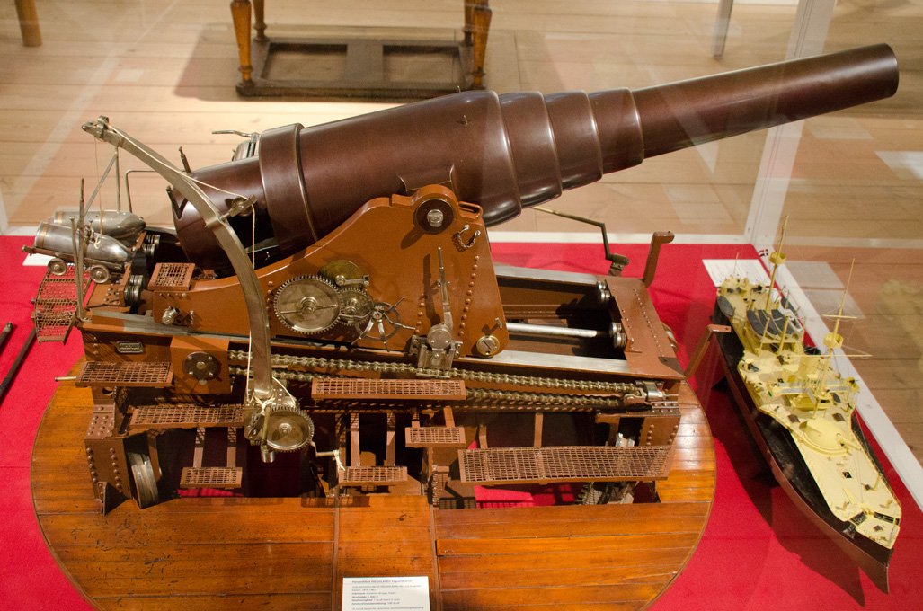 Large-scale instruction model for the 30,5 Rk on-board the Danish HELGOLAND in the Orlogmuseet, Copenhagen
The guns and their carriage suitably impressed the naval circles of the time, so that it is quite well documented in the German and foreign literature of the time. Krupp was also able to sell this gun (just over ten years after the German-Danish war of 1864!) to the Danish Royal Navy for use in the HELGOLAND. A large-scale instruction model survives in the Orlogmuseet in Copenhagen, which shows many relevant details, even though the carriage was adapted for use in an eclosed turret, rather than the open barbette of the WESPE-Class.
http://www.dreadnoughtproject.org/plans ... 100dpi.jpg
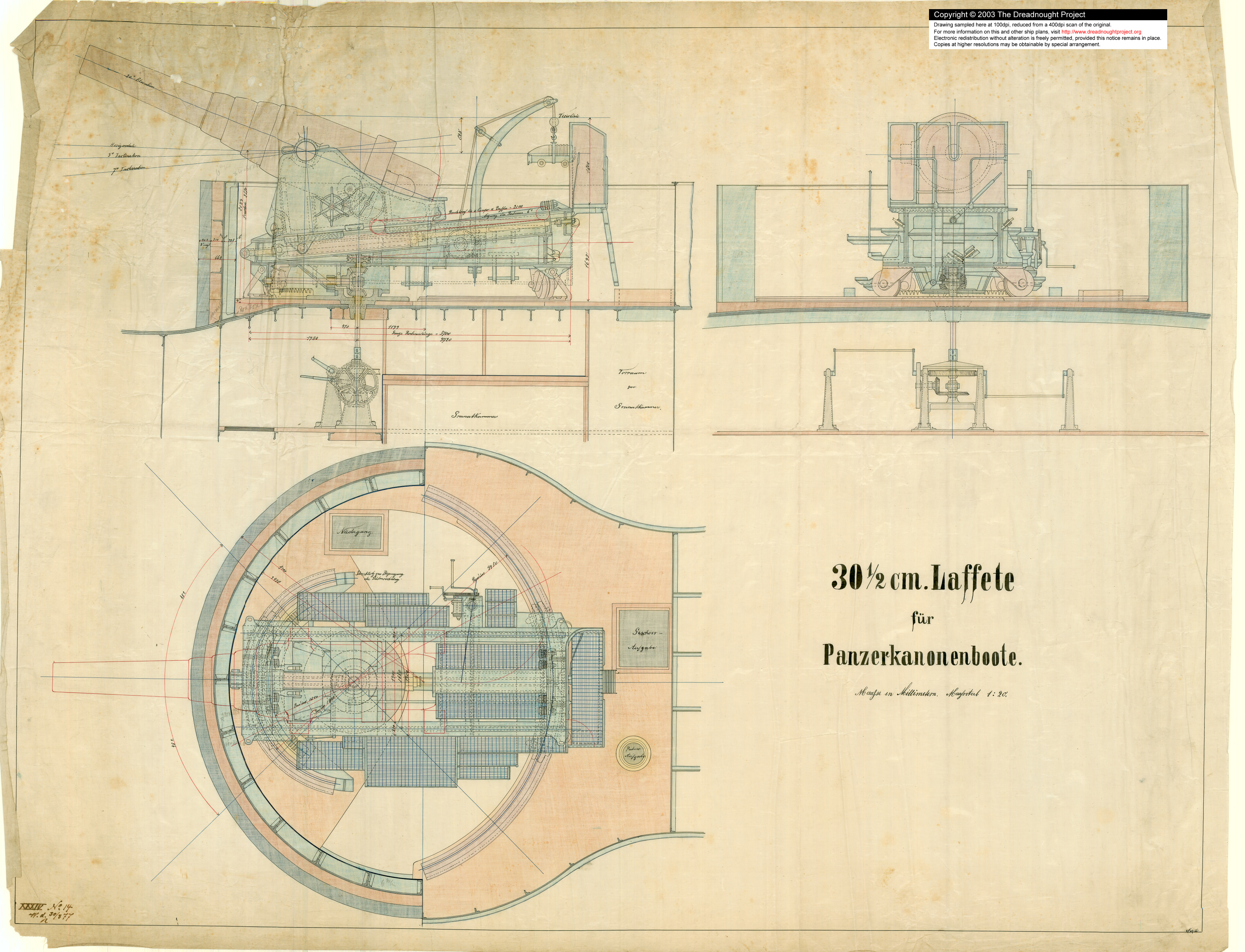
Original drawing of the mounting for the 30,5 Rk (�
http://www.dreadnoughtproject.org)
A few years ago a detailed dtawing of gun-mount originating in the adminralty archives in Berlin surfaced on the site �
http://www.dreadnoughtproject.org�. The arrangements for all the heavy Krupp guns of the time were similar, so that a visit to the Finnish fortress Suomenlinna (
http://www.maritima-et-mechanika.org/ma ... linna.html) off Helsinki was helpful; here a number of Russian clones of 28 cm coastal Krupp guns are still in place since the time, when Finnland was part of the Russian Empire.
 28 cm Krupp-clone coastal guns in the Suomenlinna-fortress off Helsinki
Rails for the Lower Carriage
28 cm Krupp-clone coastal guns in the Suomenlinna-fortress off Helsinki
Rails for the Lower Carriage
The lower carriage of the gun is supported on four races that run on semicirucular cast-iron rails bolted to the deck inside the barbette.
These rails need to go into their place in the barbette early during the construction. The same applies to the semi-circular toothed rack that is part of the gun-training machinery. I decided to make the rails from steel, even though ferrous metals in model construction are frowned upon by many. My justifications were that it is difficult to represent cast iron or steel by paint and that there hundreds of models in museums around the world that contain iron. I have used steel in models some twenty years ago and presumably due to the lacquering they shows no signs of rust.
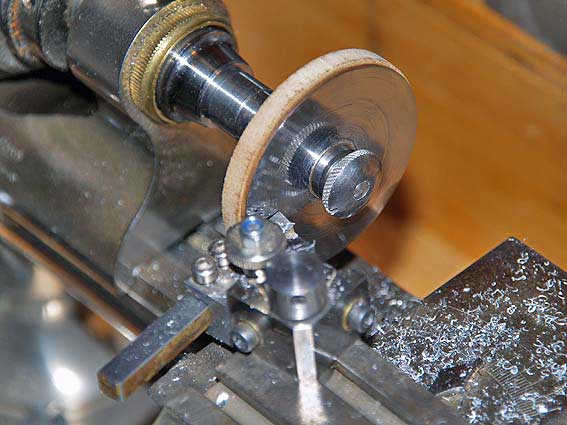 Roughing out the rails from a metal disc with the backing of a wooden disc
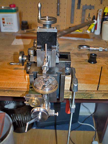
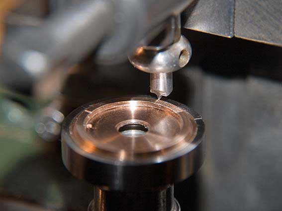
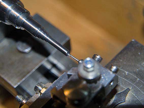
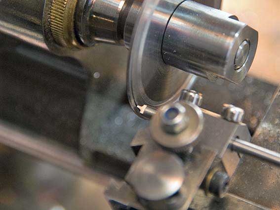 Grooving the rails with a specially ground bit
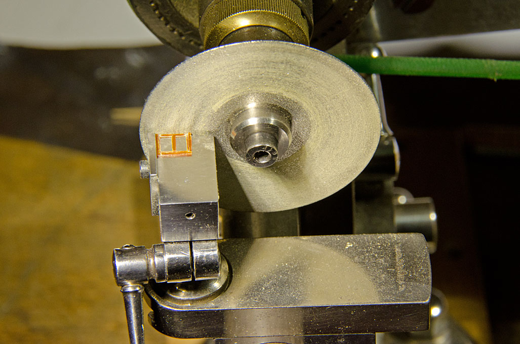
Cutting thin disks from round stock of large diameter is a pain I wanted to avoid. Against my better knowledge I picked a suitably sized steel washer as starting material. Unfortunately, the steel used did not machine very well and lot effort was spent to avoid chatter marks while turning and to obtain a reasonably good finish. The various types of wheel collets and chucks available for the watchmaking lathe came into good use for working on inside and outside diameters of these discs. The rails were shaped using a specially ground forming tool.
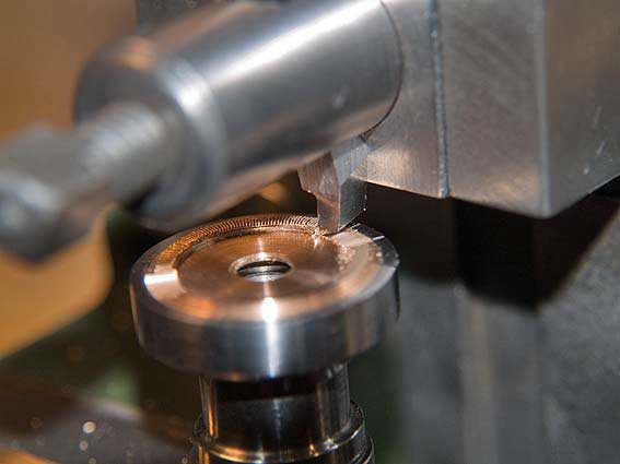
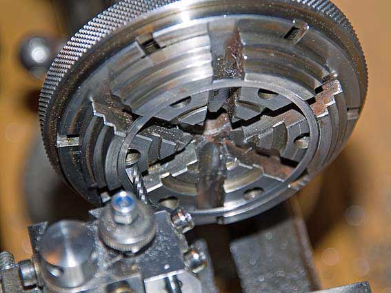 Cutting out the inside of the large ring for the tail-races of the lower carriage, while holding it in a so-called bezel-chuck
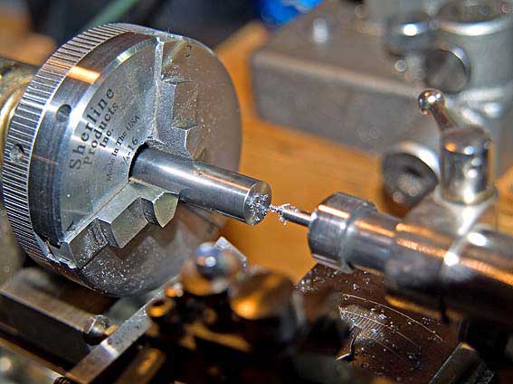
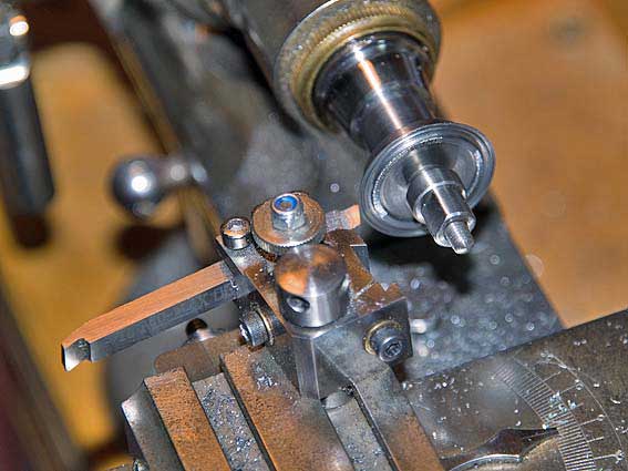 Trimming the outside of the smaller forward ring holding the material in a so-called wheel-chuck
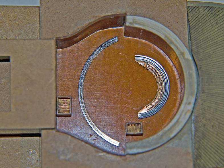 The rails laid out in the barbette
To be continued ...
The rails laid out in the barbette
To be continued ...
Re: 1:160 S.M.S. WESPE Armoured Gunboat (1876)
Posted: Sun Feb 01, 2015 11:35 am
by JIM BAUMANN
and this is where your superlative craftsmanship and mastery of machine tools shines through
just excellent!
love the barbette rails !!
Jim Baumann

Re: 1:160 S.M.S. WESPE Armoured Gunboat (1876)
Posted: Thu Feb 05, 2015 3:17 am
by wefalck
Thanks, Jim, my hands are not as dexterous and steady as those of certain other people here on the Forum, so I have to resort to machines
***************
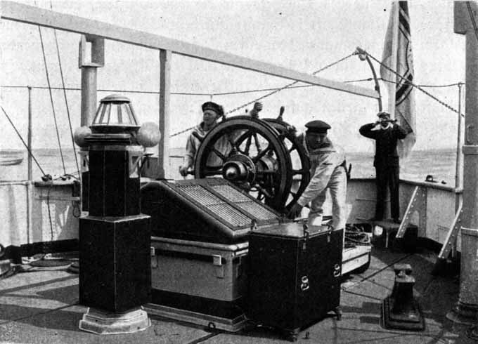
Rack-and-pinion drive for training the gun
The gun was trained by pinion acting on a circular rack. The pinion was driven from under deck by a sets of gears and a couple of cranks manned by a number of sailors. The chief gunner was able to connect and disconnect the drive with levers from his aiming-stand behind the gun.
I set up my hand-shaper (
http://www.wefalck.eu/mm/tools/shaper/shapers.html) for cutting the rack teeth, but had to throw away the first two attempts because of the poor material and because - again against better knowledge - I did not lock the traverse slide when cutting. The table was removed from the shaper and the home-made dividing head bolted on instead. For lack of a proper tool grinder (another project now in hand) I hand-ground a cutter for the rack teeth (0.1 mm at the bottom) from a rod of high-speed steel. For holding this tool-bit in the shaper, an old lantern-style tool holder from the watch lathe came very handy. The unwanted parts of the ring were cut away on the shaper using ordinary left and right hand lathe tools. Finally the necessary sections were trimmed off with a fine saw blade on the lathe's sawing table.
 Hand-shaper set-up for cutting the toothed rack
 Cutting the toothed rack with a specially ground tool
 Cutting away the unwanted part of the ring with an ordinary tool
Rails and rack provisionally in their place inside the barbette
To be continued ...
Cutting away the unwanted part of the ring with an ordinary tool
Rails and rack provisionally in their place inside the barbette
To be continued ...
Re: 1:160 S.M.S. WESPE Armoured Gunboat (1876)
Posted: Thu Feb 05, 2015 5:41 am
by Folgore
Hello wefalck
What a lovely and creative build! A small lathe like yours
is standing right on top of my iwishicouldafford list.
I'm looking forward to seeing this build progressing.
Sincerely
Chrischan
Re: 1:160 S.M.S. WESPE Armoured Gunboat (1876)
Posted: Thu Feb 12, 2015 4:38 am
by wefalck
Well the machine tools are all antiques and one has to dig quite deep into the pockets these days for something like them, if you can still find them - 10, 15 years ago it seems to have been easier.
*********
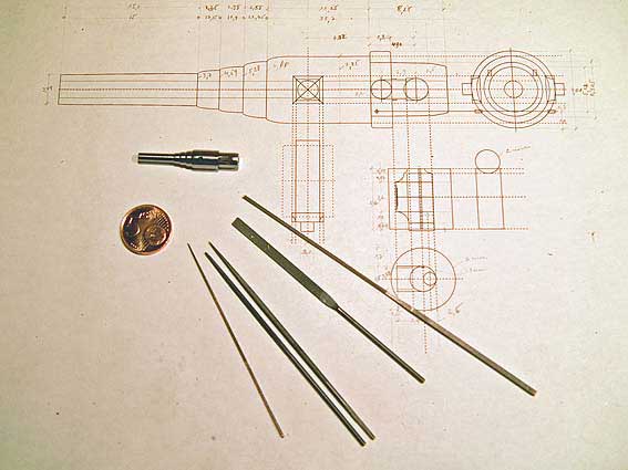
The gun barrel and lock
Turning the barrel
Because there will various visible areas of bare metal, the material of the original, that is steel, was chosen. A piece of round bar was faced, centred and rough drilled for the bore. This hole served as a protective counter bore for the tailstock centre during the following turning operations. In order to get a good finish the automatic longitudinal feed for the lathe was set up with the change gears. Unfortunately the minimum feed per revolution on the watchmaking lathe is still too high to get a 'mirror' finish. One day I have to construct some sort of reduction gear. The outer part of the barrel has a slight taper (1 degree included angle) and the top-slide was off-set accordingly for this operation.
 Facing and centring a piece of steel rod for the gun barrel
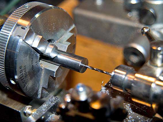 Rough drilling of the gun barrel
 Turning the barrel using the automatic fine feed
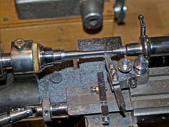 Taper-turning with slide rest off-set
For rounding off the ends of the rings the lathe�s hand tool rest came to good use. The work was finished off with fine wet-and-dry paper (remember to cover ways!) and steel wool. The bore was bored to diameter using the slide-rest and a micro-boring tool. I had originally envisaged to also show the rifling, but a quick calculation told me that for a 1 mm bore and 72 rifled fields I would need a tool edge tha is just over 0.04 mm wide ...
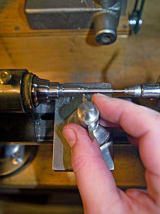 Rounding the 'rings' using a hand turning rest
 Boring the barrel using a micro boring tool
To be continued ...
Boring the barrel using a micro boring tool
To be continued ...
Re: 1:160 S.M.S. WESPE Armoured Gunboat (1876)
Posted: Wed Feb 18, 2015 10:54 am
by wefalck
Re: 1:160 S.M.S. WESPE Armoured Gunboat (1876)
Posted: Wed Feb 18, 2015 11:19 am
by PICKETBOAT
Wefalck
Quite stunning.
I think I have probably made this comment already but I will make it again. I thought I was getting pretty good a building ship models but after seeing the quality of this build I think I might just give up and take up knitting instead!
Looking forward to the next instalment.
Re: 1:160 S.M.S. WESPE Armoured Gunboat (1876)
Posted: Sat Feb 28, 2015 2:46 pm
by wefalck

� I would rather see continue with boats - unless you were knitting some torpedo-nets for instance
****************
Lock for the 30,5 cm gun
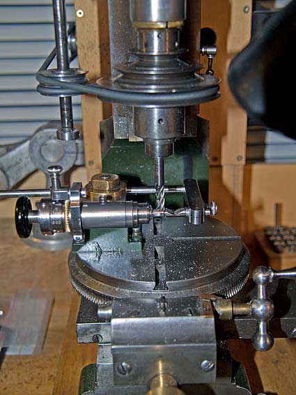
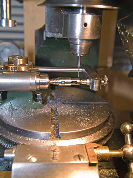
The next thing to be tackled was the lock piece or �wedge�. This 'wedge' has a rather complex shape with a flat front, but a round back and various recesses and cut-outs. I decided it would be best to undertake most of the machining operations while it is still attached to some (round) material that can be easily held in a collet. The round back was milled in an upright collet holder (
http://www.maritima-et-mechanika.org/to ... ments.html) on my mill's rotary table after the various coaxial holes had been drilled and the flat sides milled, all in the same set-up. For machining the other recesses the piece had to transferred to the diving head on the mill.
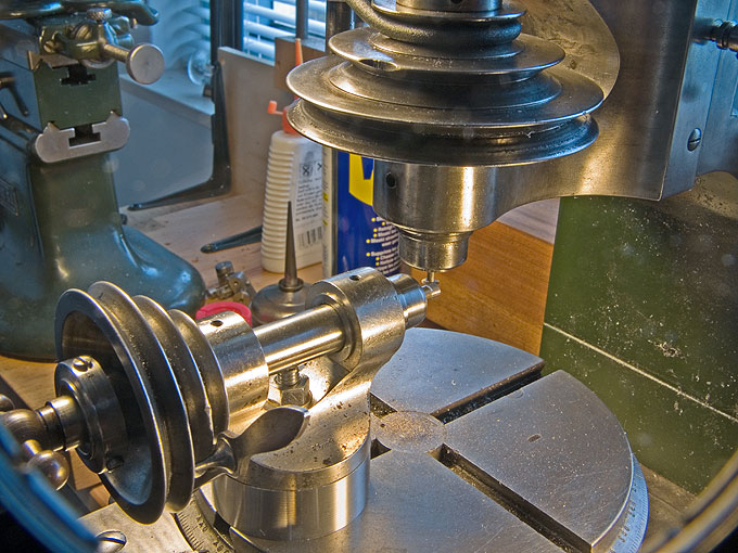
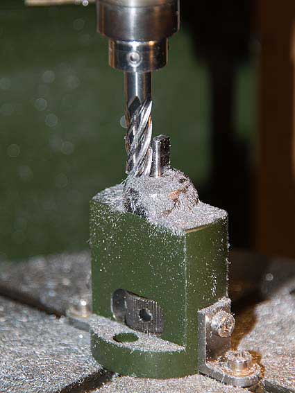 Round-milling the lock piece in an upright collet-holder on the rotary table
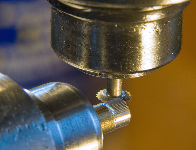
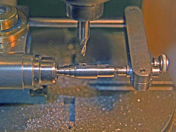
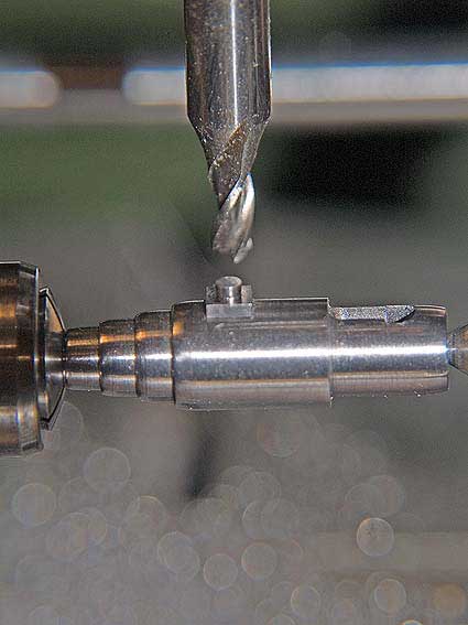
 Cutting off the finished lock piece
The most time consuming part turned out to be the cover piece for the lock, which in the prototype was fastened by five hexagonal head bolts. It holds the moving and locking screws in their place. It took me four tries before I produced a half-way satisfactory piece. Soldering the microscopic bolts (0.4 mm head diameter) in place got me quite a few grey hairs. Finally a fake locking screw was turned up and the moving screw, which moves the lock in and out, was faked from a couple of drilled-together 0.1 mm copper wires, covered in a thin layer of solder to make them look like steel.
 Milling square and hexagonal bolts
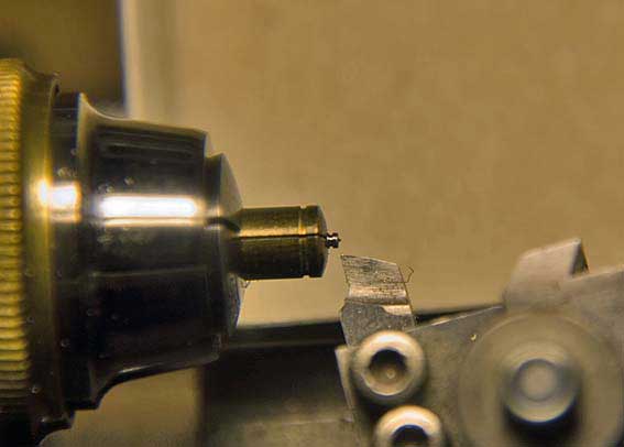 Facing the locking screw in special protective brass collet
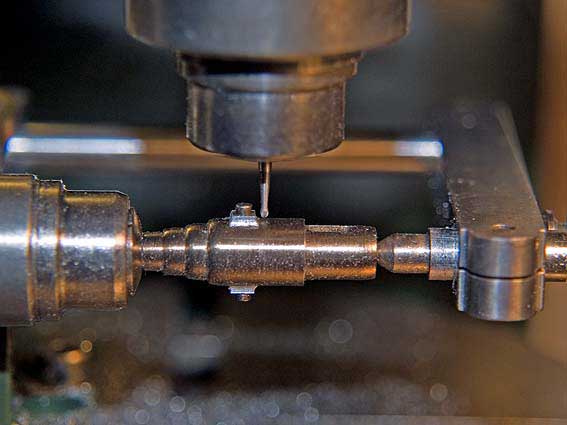
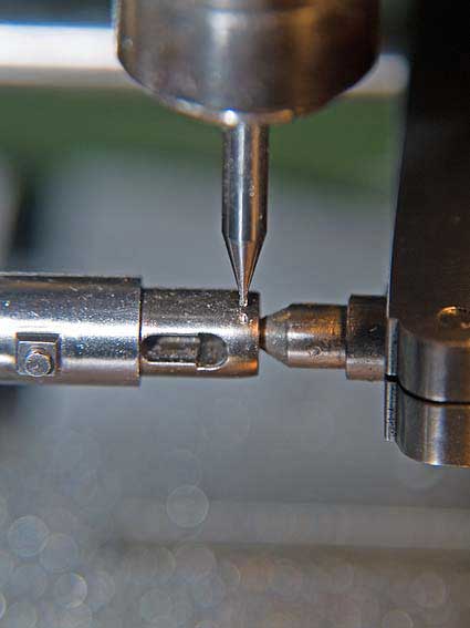
The large re-enforcement ring for the barrel was also turned up and two holes drilled into it for seating the rack quadrant that forms part of the elevating gear. In fact, I had cheated a bit, when drilling/milling the lock seat: the front of the hole should have been flat, which is difficult to machine; so I continued the elongated hole under the re-enforcement ring, which was made as a separate part and slipped over the barrel.
The various parts of the lock were assembled using lacquer and cyanoacrylate glue.
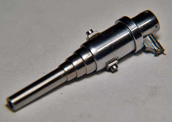
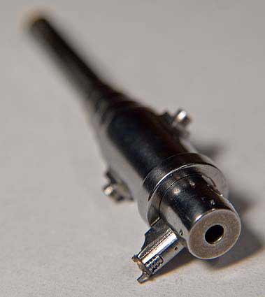
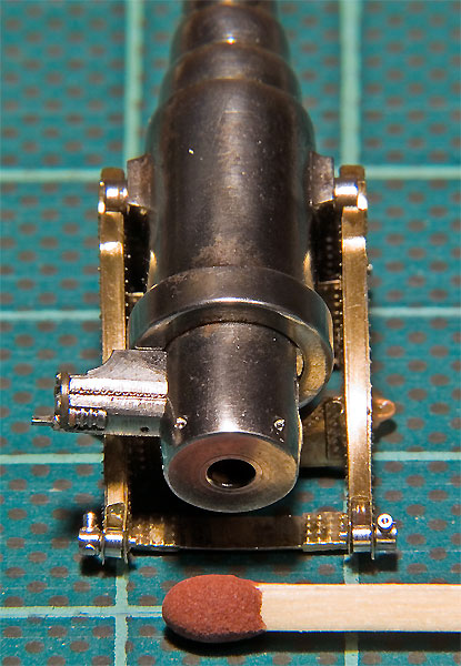
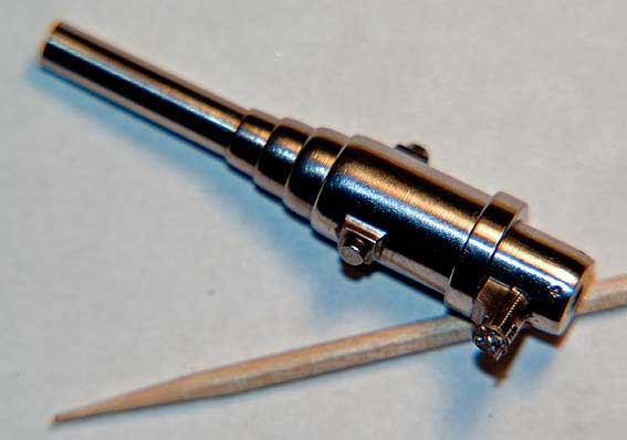 The (almost) finished gun barrel with its lock (toothpick for scale)
To be continued ...
The (almost) finished gun barrel with its lock (toothpick for scale)
To be continued ...
Re: 1:160 S.M.S. WESPE Armoured Gunboat (1876)
Posted: Sat Feb 28, 2015 7:00 pm
by GazzaS
This is absolutely beautiful work. Truly impressive.
Re: 1:160 S.M.S. WESPE Armoured Gunboat (1876)
Posted: Sat Feb 28, 2015 8:21 pm
by PICKETBOAT
You think this is amazing, then you see the toothpick and you are BLOWN AWAY.
Well done.
Re: 1:160 S.M.S. WESPE Armoured Gunboat (1876)
Posted: Wed Mar 04, 2015 7:54 pm
by Mr. Bean
I must ask,.. were you ever a watchmaker or repair of such? Your machining skills are truly impressive.
Mick
Re: 1:160 S.M.S. WESPE Armoured Gunboat (1876)
Posted: Thu Mar 05, 2015 3:08 pm
by wefalck
Thanks, gentlemen. Actually, I am an entirely self-taught 'mechanic'. Over the years the restauration of the watchmaking machines became a hobby in itself and I developed the skill accordingly. I gather the main ingredient is patience �.
*************
The upper gun carriage
Based on the profile drawings from (
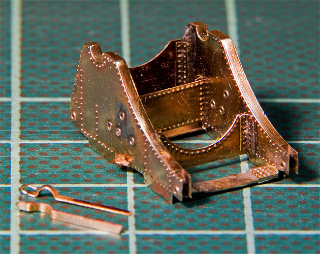
http://www.dreadnoughtproject.org) and the available contemporary photographs templates for photo-etched parts for the upper carriage were developed. The original carriage cheeks are made up from cast(?) frames that are covered in rivetted-on plates of sheet metal. The two cheeks are tied together by bracing pieces with rivetted re-enforcements. The cheeks and braces are reproduced as surface-etched parts.
http://www.dreadnoughtproject.org/plans ... 100dpi.jpg
Original drawing of the mount for the 30,5 cm gun (�
http://www.dreadnoughtproject.org)
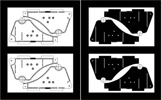 Part view of the drawings for the photo-etched upper carriage cheeks
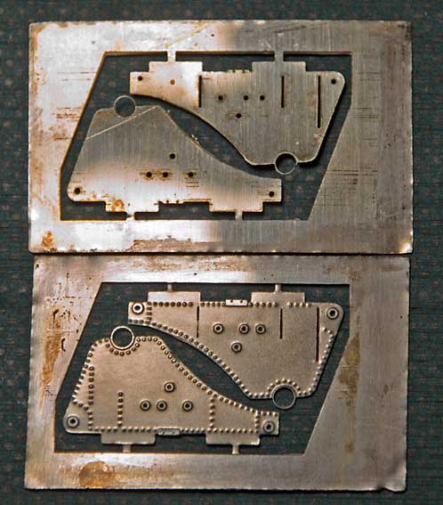 Surface etched cheeks for the upper carriage
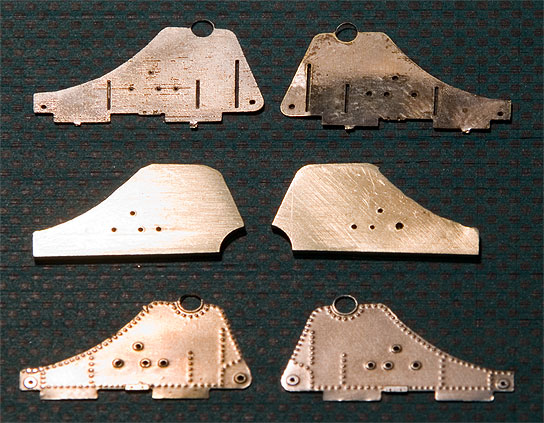 Filler and covering pieces laid out for soldering
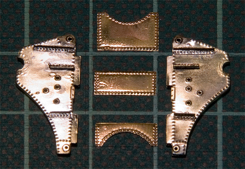 Assembled cheeks and ties laid out
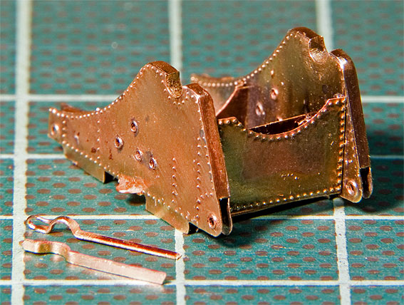
A core for the cheeks was sawn from 0.8 mm brass sheet and the etched covers soldered on. Then 'rivetted angle-irons', from etched parts were soldered on. These are connected by tie-plates. The frame of the upper carriage is also strengthend by horizontal ties. These are composites from several etched parts in order to show the rivetting. The horizontal ties were soldered to the side pieces, while the bulkhead-like ties were glued in because it would have been to difficult and risky to bring the heat for soldering at the right places. The covers for the trunnion-bearings were bent from an etched part and soldered together.
 Assembled upper gun carriage from the rear
 Assembled upper gun carriage from the front
The upper carriage was further kitted-out with wheels. The front and rear rollers were turned from steel to give them a real 'steel' appearance. On the prototype the rear rollers sit in excentric bearings that allows them to be brought into to contact with the rails on the lower carriage: when being fired the upper carriage slides back on these rails, the rollers allow it to roll back into the firing position.
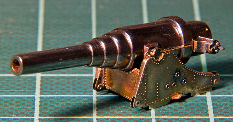 Carriage with the barrel in place. Note the trunnion bearings cover (not yet trimmed to length)
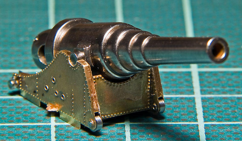
 Added the rollers plus the sockets aft for the lever that is used to turn the excentric bearings of the rear rollers
To be continued ...
Added the rollers plus the sockets aft for the lever that is used to turn the excentric bearings of the rear rollers
To be continued ...
Re: 1:160 S.M.S. WESPE Armoured Gunboat (1876)
Posted: Thu Mar 05, 2015 3:57 pm
by JIM BAUMANN
beautiful photoetch work
it looks ..." heavy "
quite a feat for a small thing eh!"
JIM B
Re: 1:160 S.M.S. WESPE Armoured Gunboat (1876)
Posted: Sun Jan 01, 2017 2:40 pm
by wefalck
I hope everyone made it safely into 2017. Now that various toolmaking and machine-building projects (
http://www.maritima-et-mechanika.org/to ... filer.html,
http://www.maritima-et-mechanika.org/to ... omill.html,
http://www.maritima-et-mechanika.org/to ... ander.html) have been completed I am returning to SMS WESPE after a long break.
First I had a look at the box with the parts already made to aid my memory a bit:
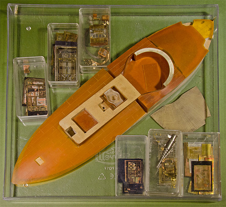
Also, the building-log proper is a great aid in recapitulating what has been done already. I hope to be able to soon report here on real progress ...
Re: 1:160 S.M.S. WESPE Armoured Gunboat (1876)
Posted: Mon Jan 02, 2017 1:59 pm
by carr
..
Re: 1:160 S.M.S. WESPE Armoured Gunboat (1876)
Posted: Tue Jan 03, 2017 5:02 pm
by wefalck
Thanks, Gentlemen, for the encouraging words.
************************************************
I am now catching up from the point, where the log had been interrupted. The work below was actually undertaken quite a while ago.
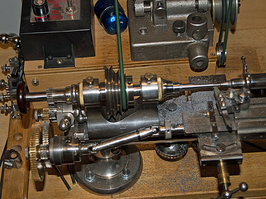
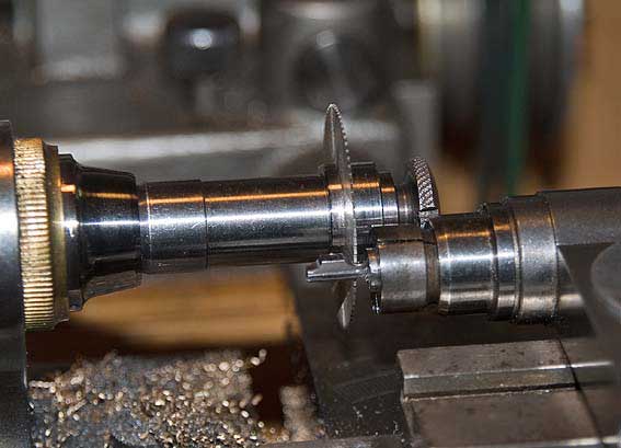
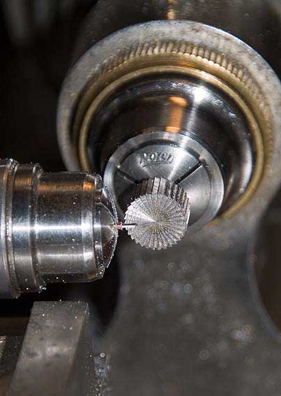
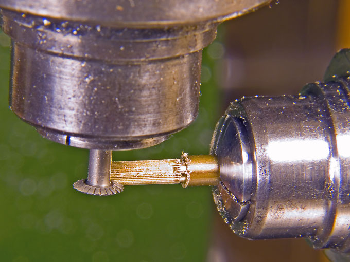
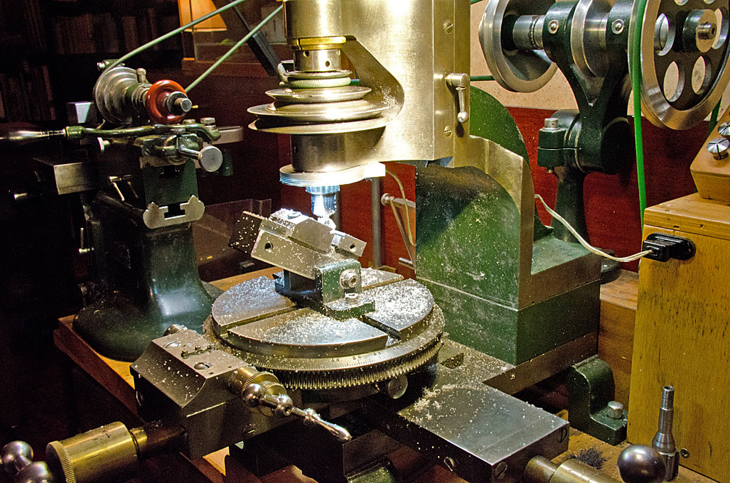
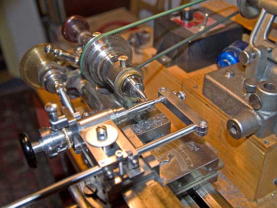
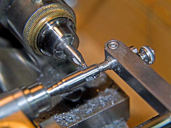
The gears were cut from brass stock in the milling machine with the help of direct dividing head and different division plates. The shape of the teeth is not exactly correct, because I used a disc-shaped burr as cutting tool. However, at this module (0.06), where the teeths are merely pitched 0.1 mm apart, this is hardly noticeable. The gear wheels are parted off from the stock on the lathe. The gear segment that will be attached to the barrel was produced in the same manner.
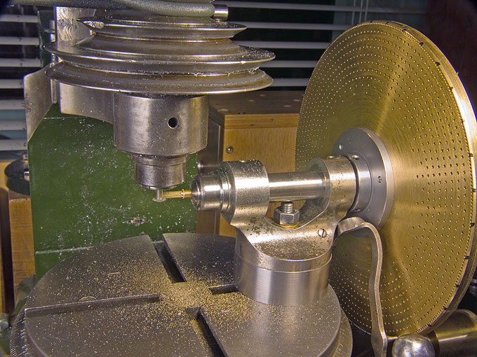
 Cutting the gears for the gun elevating mechanism using different division plates
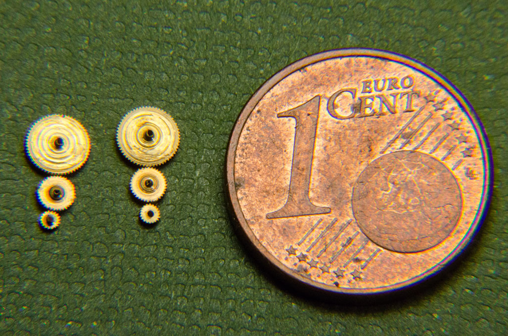 Cut-off wheels before further machining
to be continued ...
Cut-off wheels before further machining
to be continued ...
Re: 1:160 S.M.S. WESPE Armoured Gunboat (1876)
Posted: Wed Jan 04, 2017 5:07 pm
by wefalck
To get away a bit (sort of) from all that intricate micro-machining and to see something grow, I turned my attention to the skylight above the officers' quarter in the back of the boat.
 Skylight above the above officers� mess (Laverrenz)
It was, as other skylights, constructed again around a little block of Plexiglas� that was milled to shape.
 Milling to shape a small Plexiglas block
The panelling was constructed from various layers of 0.4 mm thick Pertinax. For sanding the edges square the then newly constructed micro-grinding machine came handy.
 Grinding square edges on the micro-grinding machine
On the prototype the upper part of the skylight could be lifted off and the coamings of the hatch had half-round trimmings around. For this something half-round of 0.4 mm diameter was required. Short length of half-round wire was produced from lengths of 0.4 mm diameter copper wire that were stuck onto a piece of aluminium that was milled flat in situ to ensure an even thickness of the half-rounds.
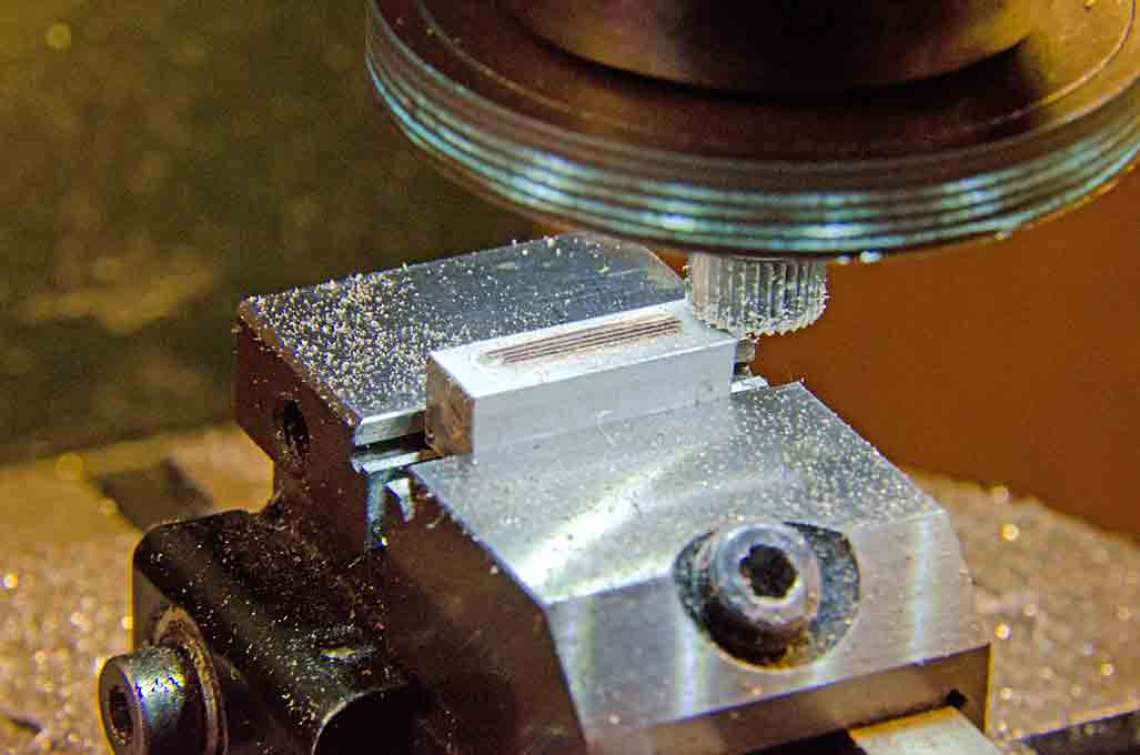 Milling half-round profiles from 0.4 mm copper-wire
 Grinding 45� bevels onto half-round 0.4 mm copper-wire
I am not absolutely happy with the result, but one has to consider that the skylight has a footprint of only 7 mm by 8 mm. Perhaps I should have another try with shop-made photo-etched parts to be designed for the purpose.
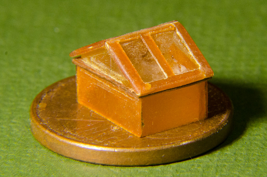 The skylight before painting
To be continued ...
The skylight before painting
To be continued ...
Re: 1:160 S.M.S. WESPE Armoured Gunboat (1876)
Posted: Tue Jan 10, 2017 4:06 pm
by wefalck
I then turned my attention back to the hull and its superstructures. All surfaces that would have been iron plating, will be covered in thin sheets of Pertinax. The necessary holes for portholes and other opening will be drilled or cut before the sheets are fixed. In this way the barbette was lined with sheets of Pertinax as was the deck-house.
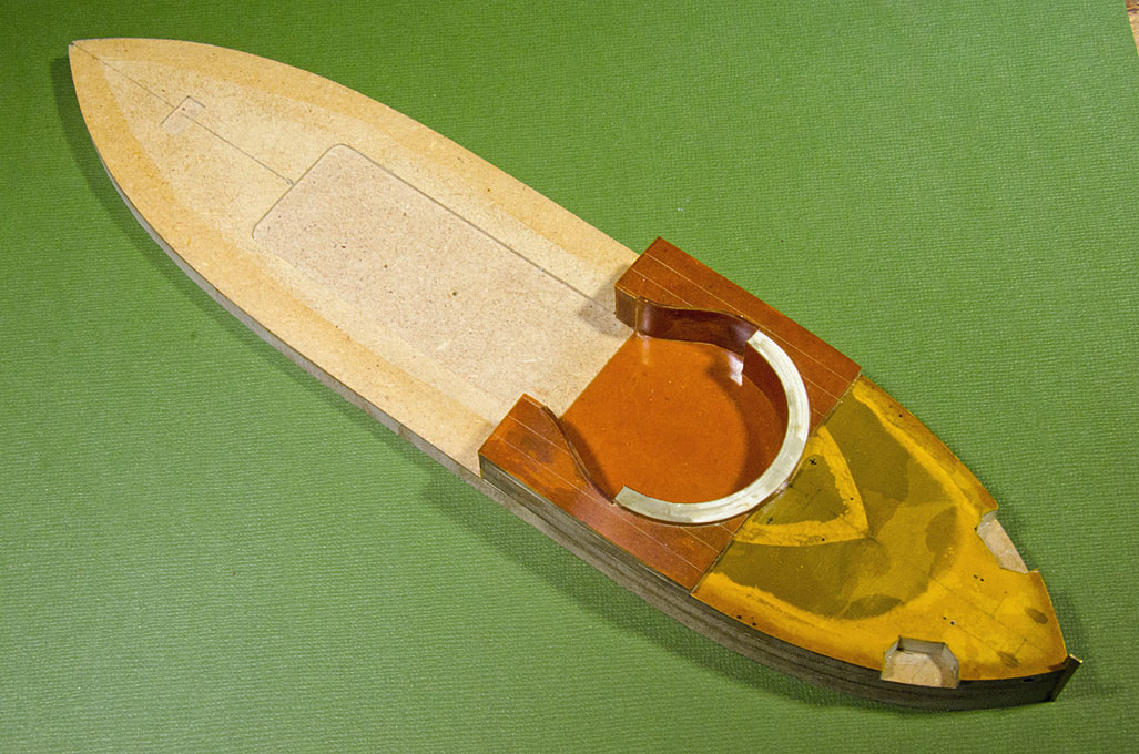 Deck-house covered in a thin sheet of Pertinax
The decks on the prototype were iron plate and this plating was covered in oil-paint that was mixed with sand and cement in order to provide a certain corrosion resistance and above all a better grip in wet conditions. A modelling plan drawn by Wolfgang Bohlayer shows wood on some decks, but evidence that since has become available shows that this was not the case. Also, linoleum decking apparently was never used on these boats.
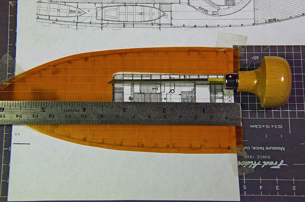
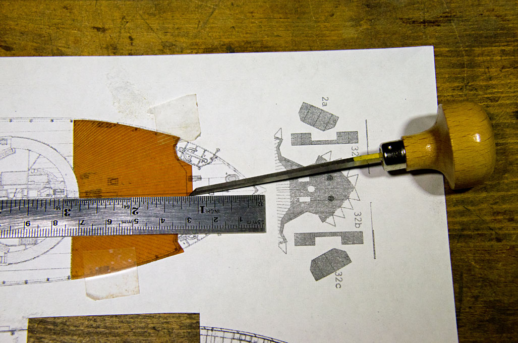 Engraving plate-lines and planking seams
As the model will show the boat in its original appearence, the plating was reproduced by engraving fine lines into thin sheets of Pertinax. All decks, including that of the barbette will covered in this way. The exception is the deck above the foc'sle that has a cover of planks, presumably to reduce wear, where the anchors were worked. This planking was laid-out in a radiant pattern, which seems to have been more resistant to the gun-blast than the more common parallel layout. The planks were also reproduced by lightly engraving the plank seams. In reality these seams would have been more or less flush with the deck, depending on the temperature and humidity, but a light engraving adds some life to the appearance.
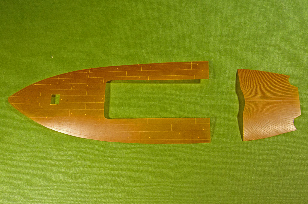 Engraved rear-deck plating and planking for the foc�sl
to be continued ...
Engraved rear-deck plating and planking for the foc�sl
to be continued ...