Thanks Gabriel!Angeliccypher wrote:um.....wow! I am loving this build! Truly inspirational.
USS Hornet CV-8 Merit In 1/200 April 1942
Moderators: BB62vet, MartinJQuinn, JIM BAUMANN, Jon, Dan K
- Iceman 29
- Posts: 1945
- Joined: Tue Sep 29, 2020 4:35 pm
- Location: Bretagne, France
Re: USS Hornet CV-8 Merit In 1/200 April 1942
Pascal
�Battleship Bretagne 3D: https://vu.fr/FvCY
�SS Delphine 3D: https://vu.fr/NeuO
�SS Nomadic 3D: https://vu.fr/tAyL
�USS Nokomis 3D: https://vu.fr/kntC
�USS Pamanset 3D: https://vu.fr/jXGQ
�Battleship Bretagne 3D: https://vu.fr/FvCY
�SS Delphine 3D: https://vu.fr/NeuO
�SS Nomadic 3D: https://vu.fr/tAyL
�USS Nokomis 3D: https://vu.fr/kntC
�USS Pamanset 3D: https://vu.fr/jXGQ
-
Charybdis
- Posts: 101
- Joined: Tue Jan 06, 2015 5:28 pm
Re: USS Hornet CV-8 Merit In 1/200 April 1942
My God... I'm dizzy looking at so much detail. This is a truly incredible project.
- Iceman 29
- Posts: 1945
- Joined: Tue Sep 29, 2020 4:35 pm
- Location: Bretagne, France
Re: USS Hornet CV-8 Merit In 1/200 April 1942
Slowly backwards, but the work goes forward!
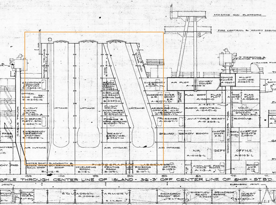
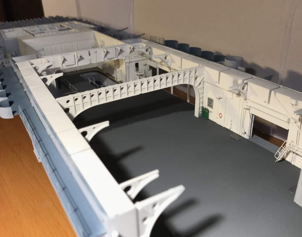
I messed up a bit yesterday when I put my structural reinforcements from the flight deck into the forward garage. I'm beginning to understand the philosophy behind this hangar ceiling, which is heavily loaded with all kinds of scrap metal... It's better, as there are still tens of meters to go to the stern and a mistake made at the bow will be difficult to make up for later.
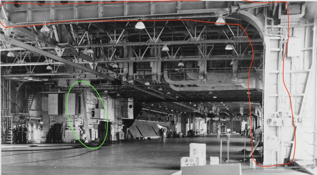
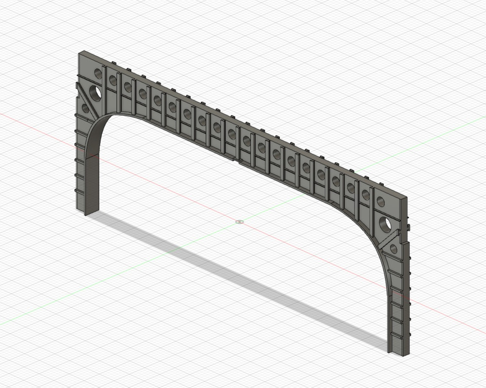
We see surrounded in red one of the main couples supporting the flight deck, there is another support at the level of the bomb lifts. We see it on the green picture, bolted to the ground. Its shape is nice to make.
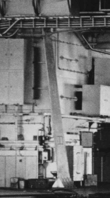
I made this beautiful masterpiece very wide, it brings a lot to the details of the hangar, there will be others more back to design.
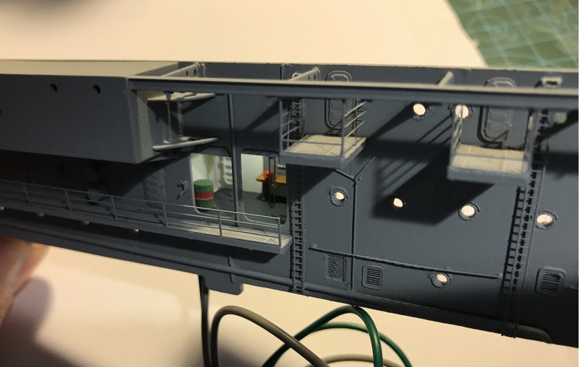
It was necessary to glue the bulkheads before installing this piece. The pt and sb housings are still removable, to install the LED wiring. I already passed the main wires to Sb.
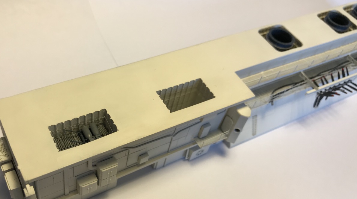
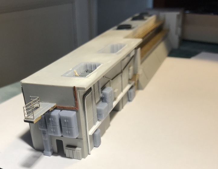
I started to take care of the central block under the island. I've done the shafts for the two bomb elevators. They open up to the front of the island at Portside . Unfortunately their location, which seems correct on the flight deck, does not correspond to their location in the central block, there is a big discrepancy.
I wanted to represent an open hatch on the deck with the arrival of the bombs. That won't be possible. Nothing sticks. and it is too complicated to rectify, at the flight deck level (think of the wooden deck), or at least complicated at the central block level, but not much better. So I don't touch anything.
So the scene will look like this after some reflection:
Flight deck, one of the two elevator hatches open, the stage is flush with the bridge loaded with the bomb.
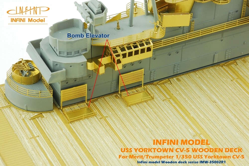
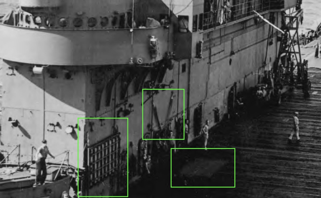
We see on this capture of the film shot on the Hornet, the two elevator hatches. The hatches are opened with foam hoists, it's not hydraulic apparently. I discovered thanks to this film, the usefulness of these two hoists that I had seen on other photos well before.
https://youtu.be/NfmQr9mQMJk

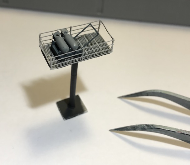
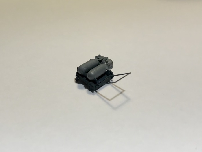
Hangar: When you remove the bridge, you will see one or two elevator platforms at different heights loaded with B-25 bombs.
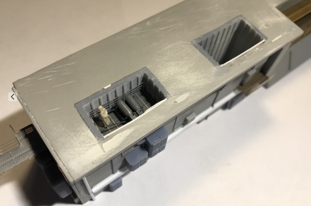
So I designed the two elevator shafts, cut out the flight deck, and the roof of the central block of the hangar to insert the two shafts properly.
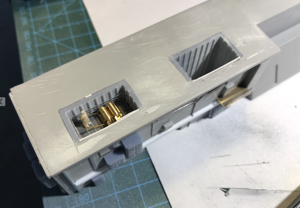
I would have other inserts to make more on the back of the block for the machine ventilation and the chimney pipes that we will be able to see the deck once removed. Beautiful parts in perspective!
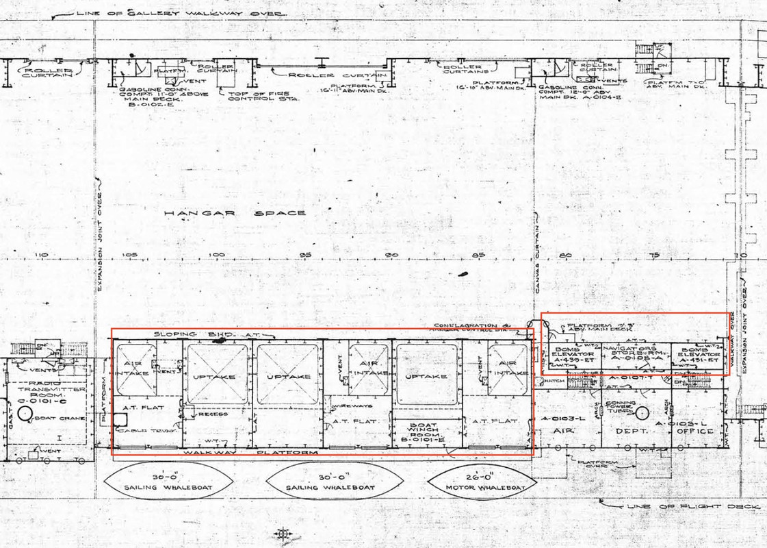
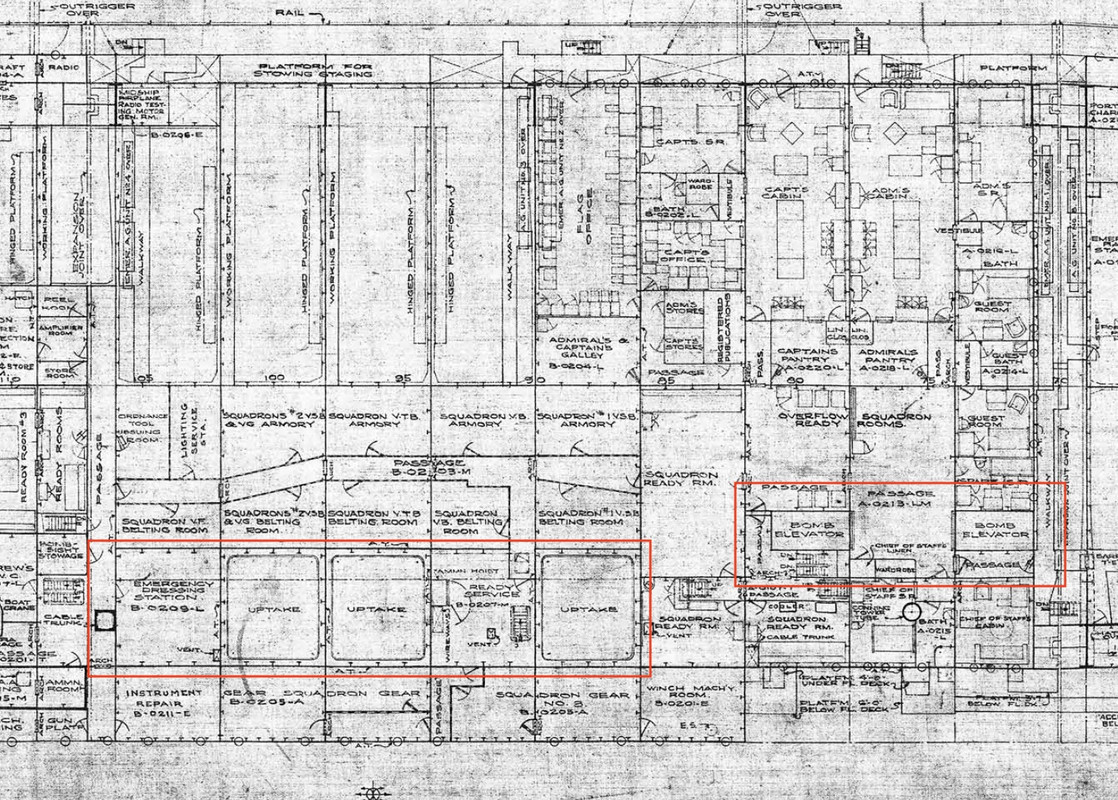
On the central block, I "gummed" on the central partition all the existing reliefs, pipes etc... to place scratch.
My progression is similar to that of a tunnel boring machine, I dig the tunnel, I lay the concrete plates, the accessories, then the rails...
and so on towards the back.
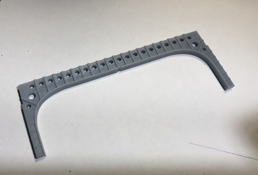

A little too thick, have to modify also this one.

Ammunitions elevator cage:


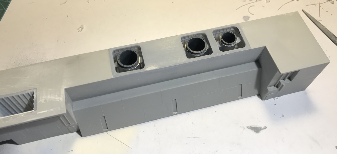
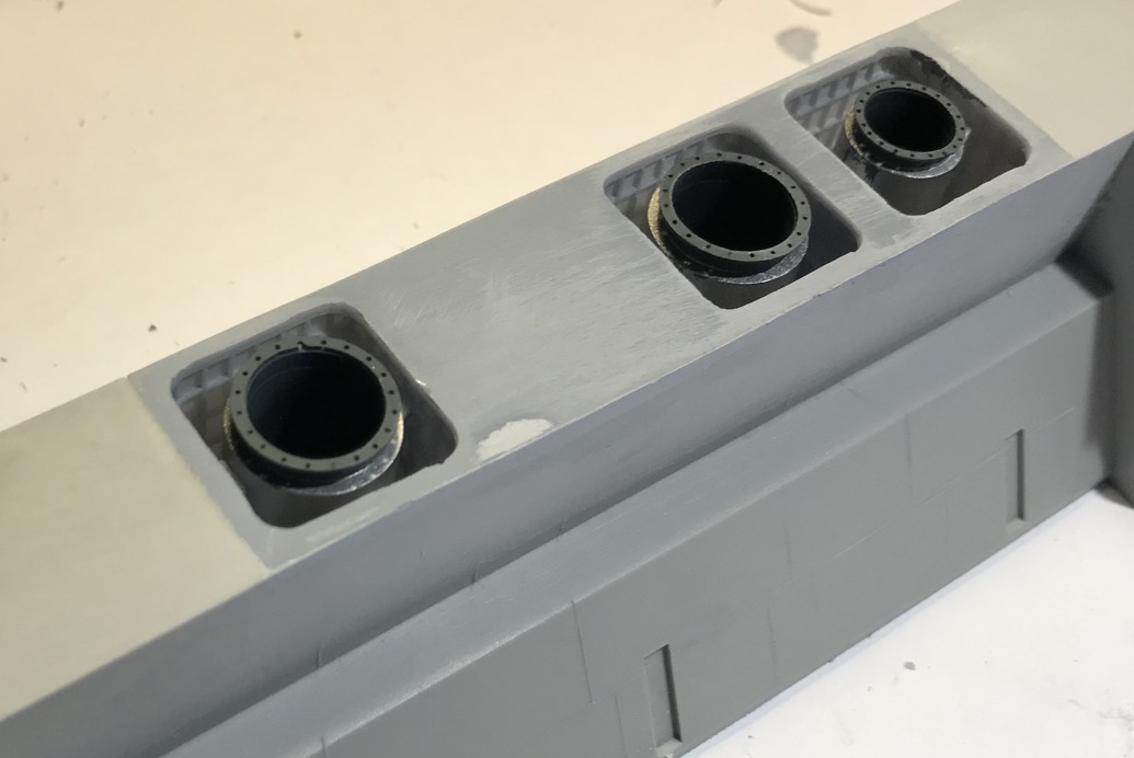
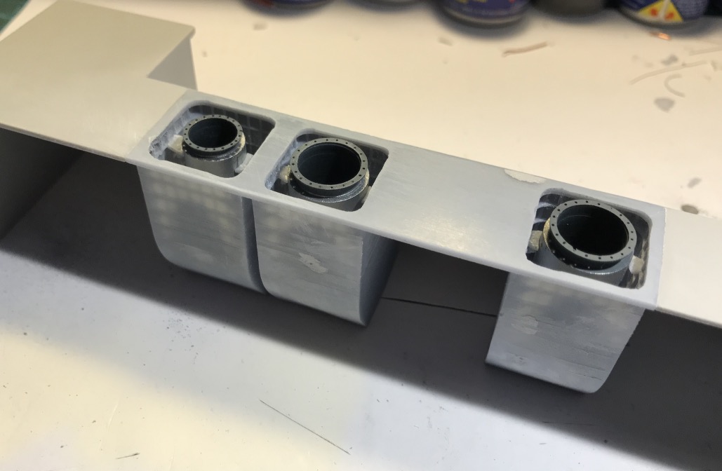
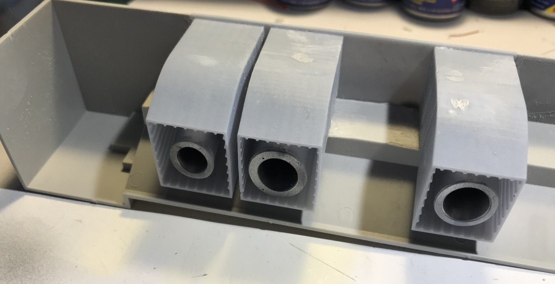
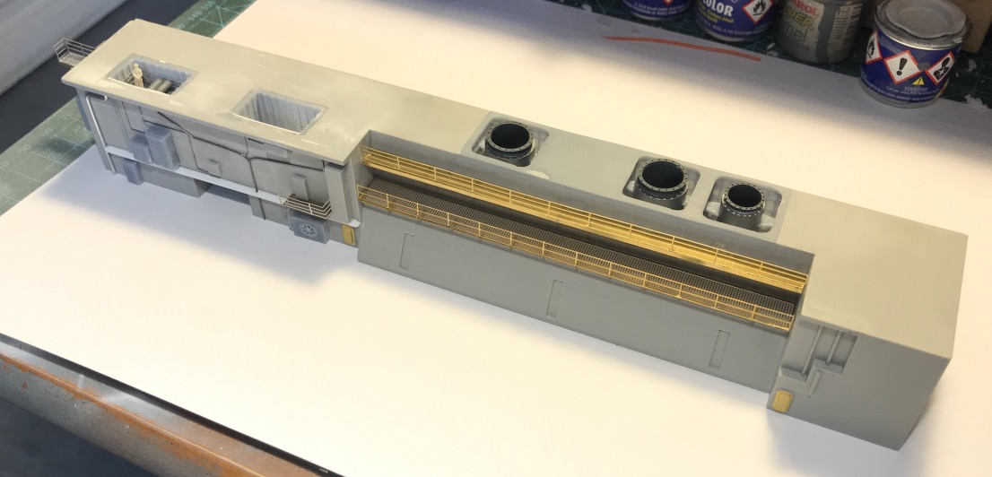
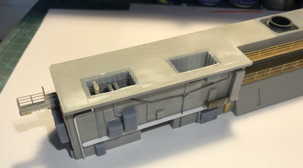
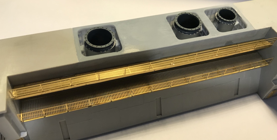
I'm working on the exhaust gas pipes of the nine boilers. There are 3 of lesser capacity on the aft, so the rear exhaust pipe is smaller than the two other.
I don't represent the ventilation casings of the different machine compartments.


Here is the 3D creation process, step by step, of the different objects that will compose this part of the central block.
First I make a 2D sketch of the platform that will replace the part I cut out of the block.
It allows me to place the different dimensions of the openings to be created.

After I extrude this drawing to the thickness of the plastic of the block, I now have a good base to start with.
I do the same on the sketch for the partitions of the casing.

I extrude the 4 walls up to the height of the elbow, as the chimney flue runs at an angle of 60� at one point.So I have to plan the next step...
As the three are identical, I'm focusing on this first one to finish it completely, I'll do a copy/paste later.
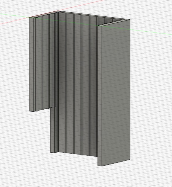
I'm working on the vertical wall stiffeners.

That I extrude too.

Then the horizontals, 5.


Then we do copy and paste, it goes fast.


I create the first exhaust pipe, it is surrounded by insulation, probably asbestos at the time, confined with thin sheet metal. It's not done like that anymore of course, nowadays, we mainly use rock wool which resists well to high temperatures.
A bit like here on the exhaust outlet of the single turbocharger of this 14000 HP 2-stroke Burmeister B&W engine, the part with a larger diameter contains the expansion bellows with its mounting flanges. Personal photos.


Creation of the pipe, then its flange.


I built the pipe in two pieces that will fit together. Because it has to be easy to mount all this and above all it has to be painted in different colours. You always have to think about painting.


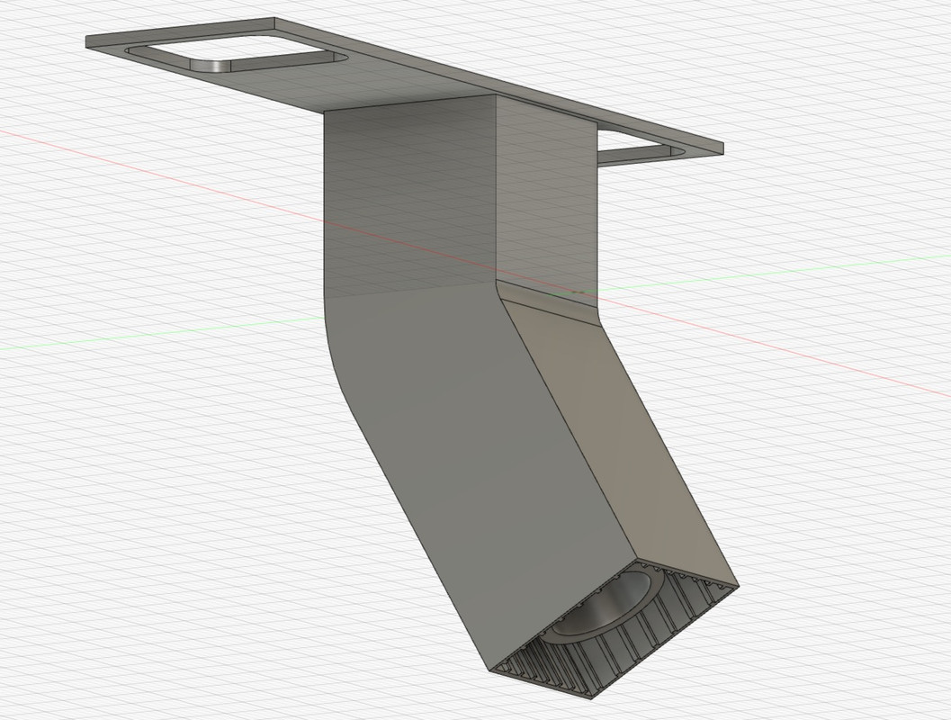
I extrude all this but by bending the shapes along a very precise axis and angle, that of the block.

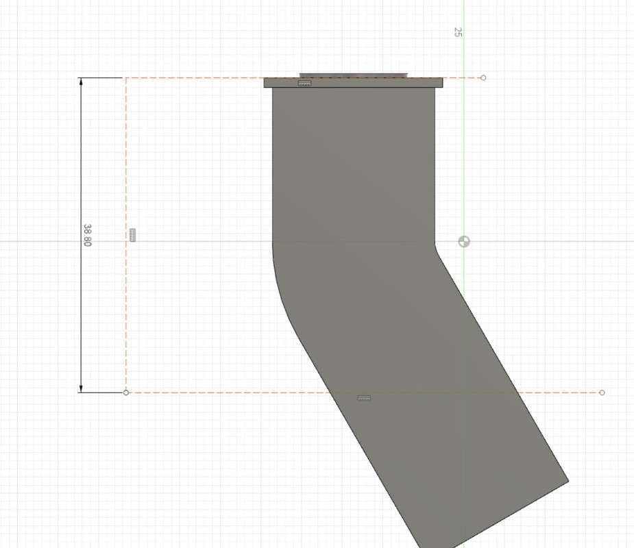
I draw a construction line that will give me the position of the hangar floor thanks to the dimension in relation to the ceiling of the block, that's where I have to cut the casing and the pipe.

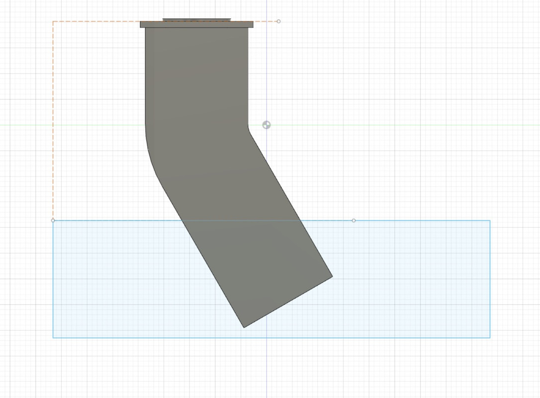
From there, I create a rectangular shape which will be used as a digital cutter, I will extrude this shape but in negative, all that will pass in its field will disappear, hence the red.


Well, that's almost done for this part. The pipe anchors still have to be installed in relation to the casing.

That's it, there's still the smallest pipe left to create and position in place.

I make a copy and put it in the front slot.

No need to rebuild a pipe, I reduce the size of the big one and adapt the junction with the shed floor.

This time the module is complete, all the elements have to be saved in a .STL file in order to print them separately. Because each element will require a specific treatment for printing in terms of support.

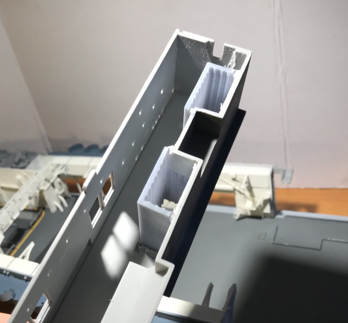
The printing plate is well filled, the reinforcing brackets are in place.
We'll see the result in 3 hours...

Printing It's not too bad, I had to re-drill the holes a bit because it's very small, with a 0.3 mm drill bit.
There is still the white paint to apply inside the ducts, white slightly yellowed compared to the white of the garage because of the heat.
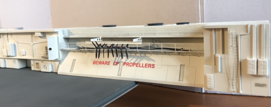
I continued to furnish the central block, including the bomb and torpedo lift. There is the spare propeller rack to be created as well.


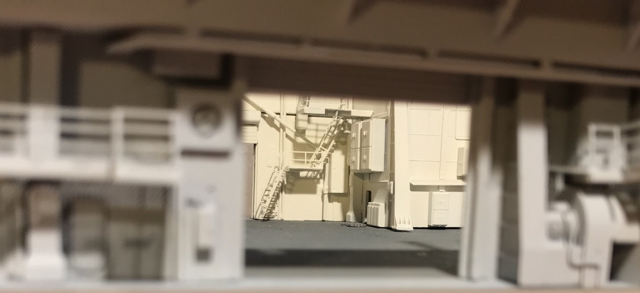
A good part of this block and the details I have added will not show because there is a garage ceiling accommodation on this level, they will be represented, cabins, offices, pilots briefing room, Admiral's cabin, Master's cabin etc..


I messed up a bit yesterday when I put my structural reinforcements from the flight deck into the forward garage. I'm beginning to understand the philosophy behind this hangar ceiling, which is heavily loaded with all kinds of scrap metal... It's better, as there are still tens of meters to go to the stern and a mistake made at the bow will be difficult to make up for later.
We see surrounded in red one of the main couples supporting the flight deck, there is another support at the level of the bomb lifts. We see it on the green picture, bolted to the ground. Its shape is nice to make.


I made this beautiful masterpiece very wide, it brings a lot to the details of the hangar, there will be others more back to design.
It was necessary to glue the bulkheads before installing this piece. The pt and sb housings are still removable, to install the LED wiring. I already passed the main wires to Sb.
I started to take care of the central block under the island. I've done the shafts for the two bomb elevators. They open up to the front of the island at Portside . Unfortunately their location, which seems correct on the flight deck, does not correspond to their location in the central block, there is a big discrepancy.
I wanted to represent an open hatch on the deck with the arrival of the bombs. That won't be possible. Nothing sticks. and it is too complicated to rectify, at the flight deck level (think of the wooden deck), or at least complicated at the central block level, but not much better. So I don't touch anything.
So the scene will look like this after some reflection:
Flight deck, one of the two elevator hatches open, the stage is flush with the bridge loaded with the bomb.

We see on this capture of the film shot on the Hornet, the two elevator hatches. The hatches are opened with foam hoists, it's not hydraulic apparently. I discovered thanks to this film, the usefulness of these two hoists that I had seen on other photos well before.
https://youtu.be/NfmQr9mQMJk


Hangar: When you remove the bridge, you will see one or two elevator platforms at different heights loaded with B-25 bombs.
So I designed the two elevator shafts, cut out the flight deck, and the roof of the central block of the hangar to insert the two shafts properly.
I would have other inserts to make more on the back of the block for the machine ventilation and the chimney pipes that we will be able to see the deck once removed. Beautiful parts in perspective!


On the central block, I "gummed" on the central partition all the existing reliefs, pipes etc... to place scratch.
My progression is similar to that of a tunnel boring machine, I dig the tunnel, I lay the concrete plates, the accessories, then the rails...


A little too thick, have to modify also this one.

Ammunitions elevator cage:
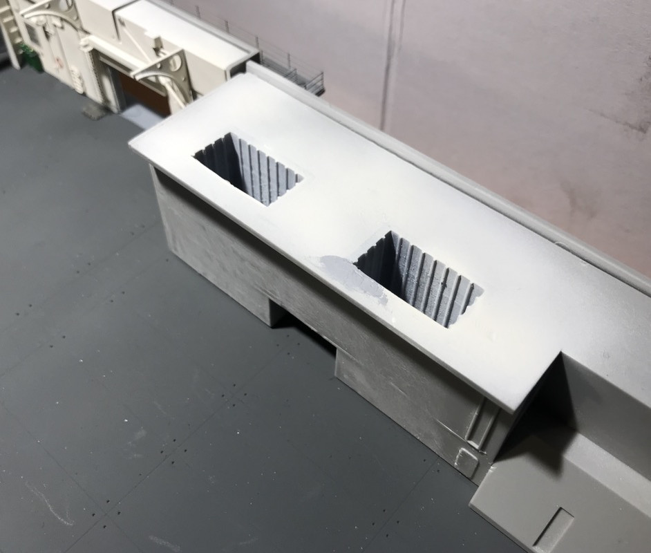

I'm working on the exhaust gas pipes of the nine boilers. There are 3 of lesser capacity on the aft, so the rear exhaust pipe is smaller than the two other.
I don't represent the ventilation casings of the different machine compartments.
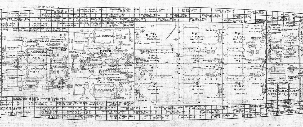
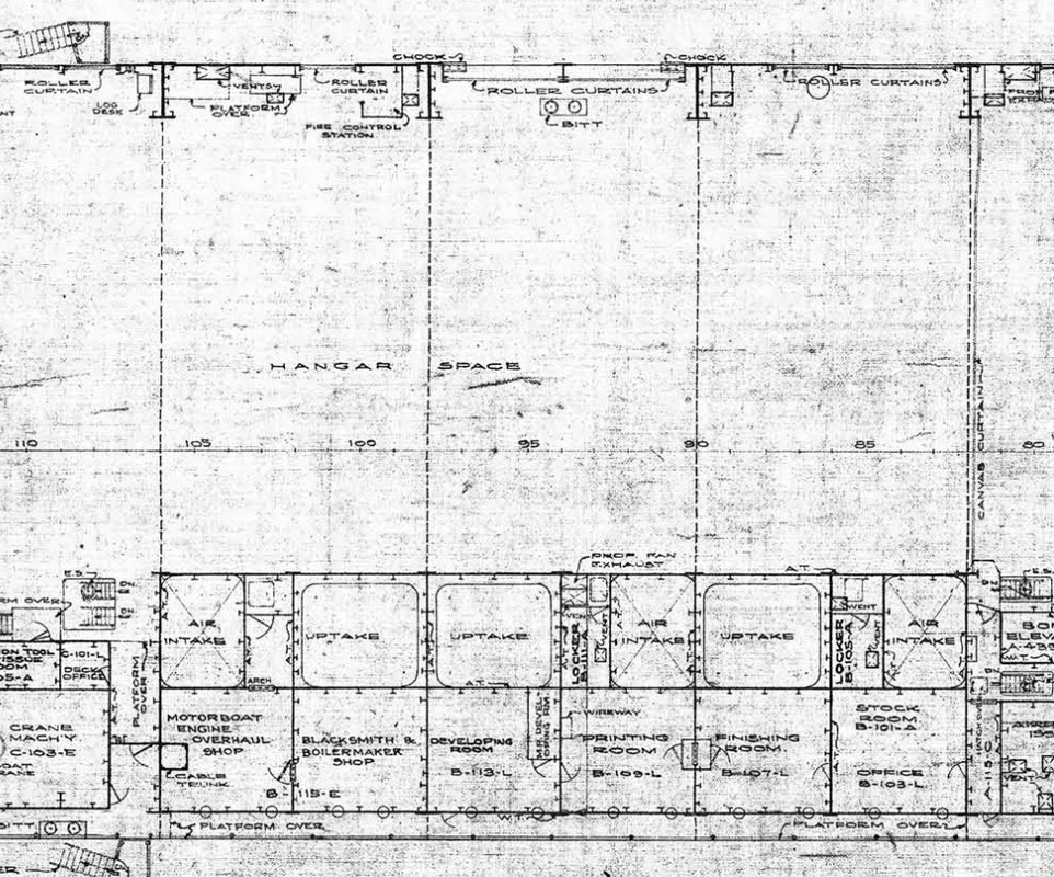
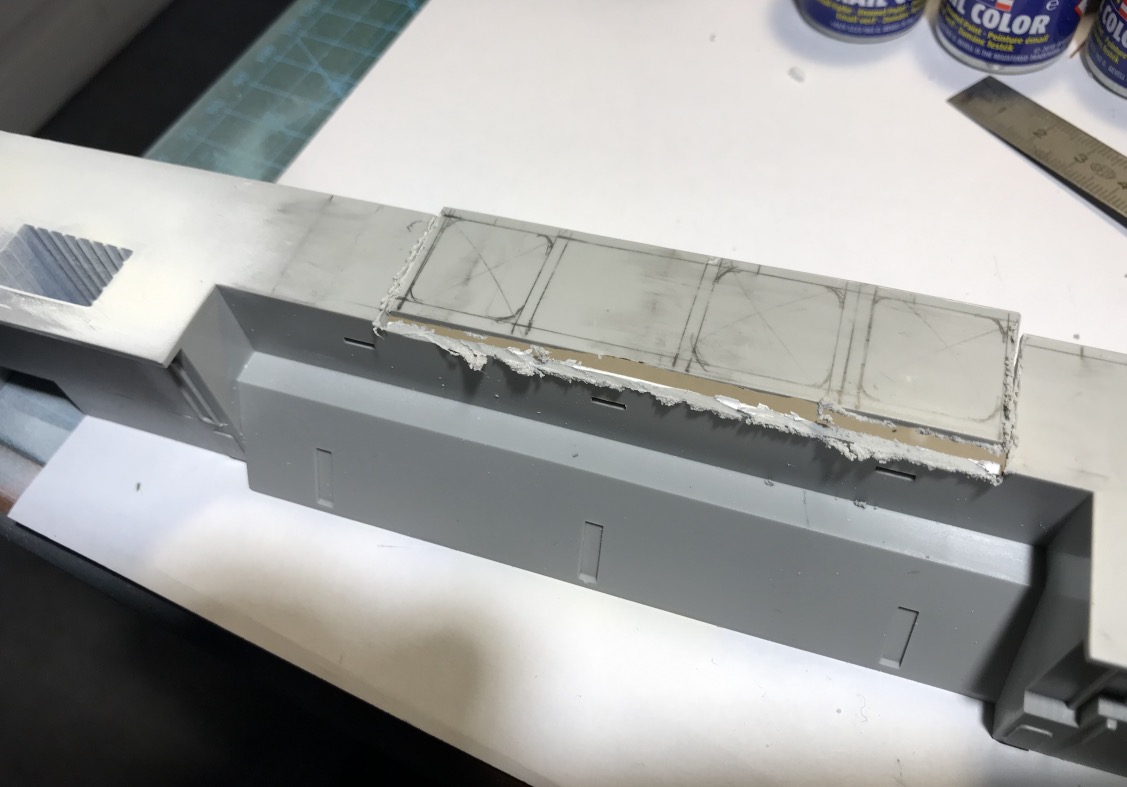
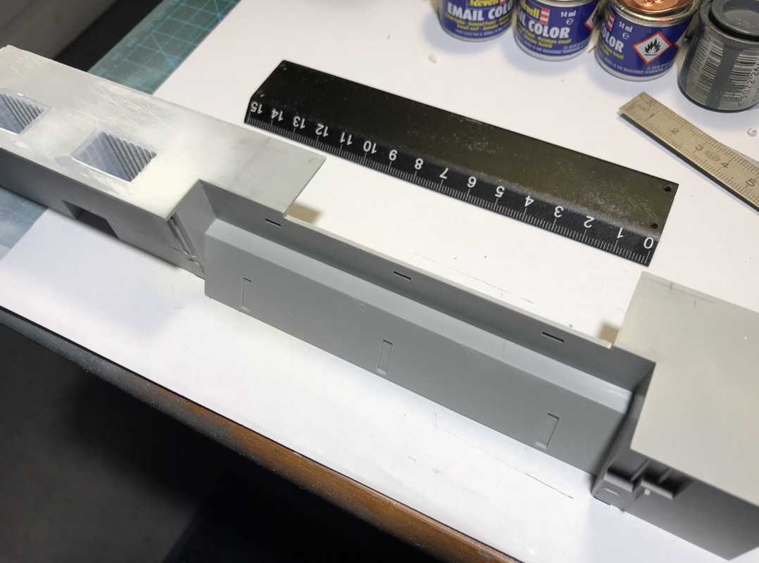
Here is the 3D creation process, step by step, of the different objects that will compose this part of the central block.
First I make a 2D sketch of the platform that will replace the part I cut out of the block.
It allows me to place the different dimensions of the openings to be created.
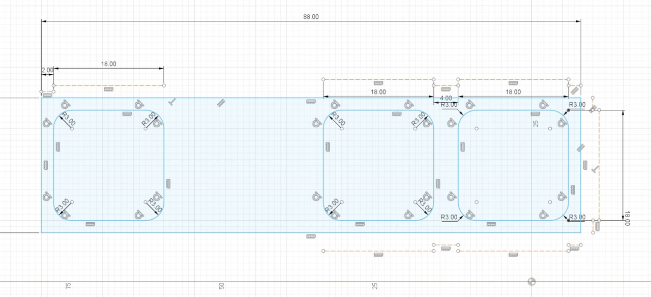
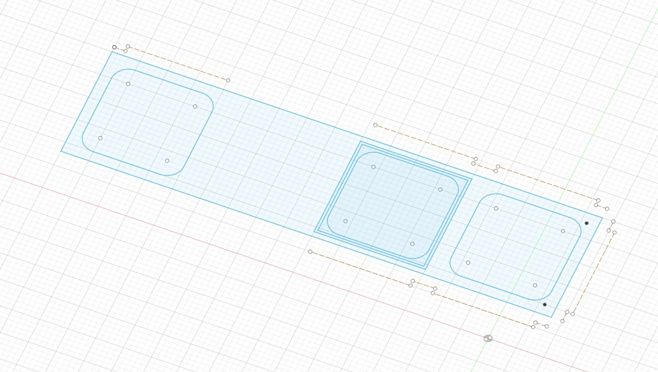
After I extrude this drawing to the thickness of the plastic of the block, I now have a good base to start with.
I do the same on the sketch for the partitions of the casing.
I extrude the 4 walls up to the height of the elbow, as the chimney flue runs at an angle of 60� at one point.So I have to plan the next step...
As the three are identical, I'm focusing on this first one to finish it completely, I'll do a copy/paste later.
I'm working on the vertical wall stiffeners.
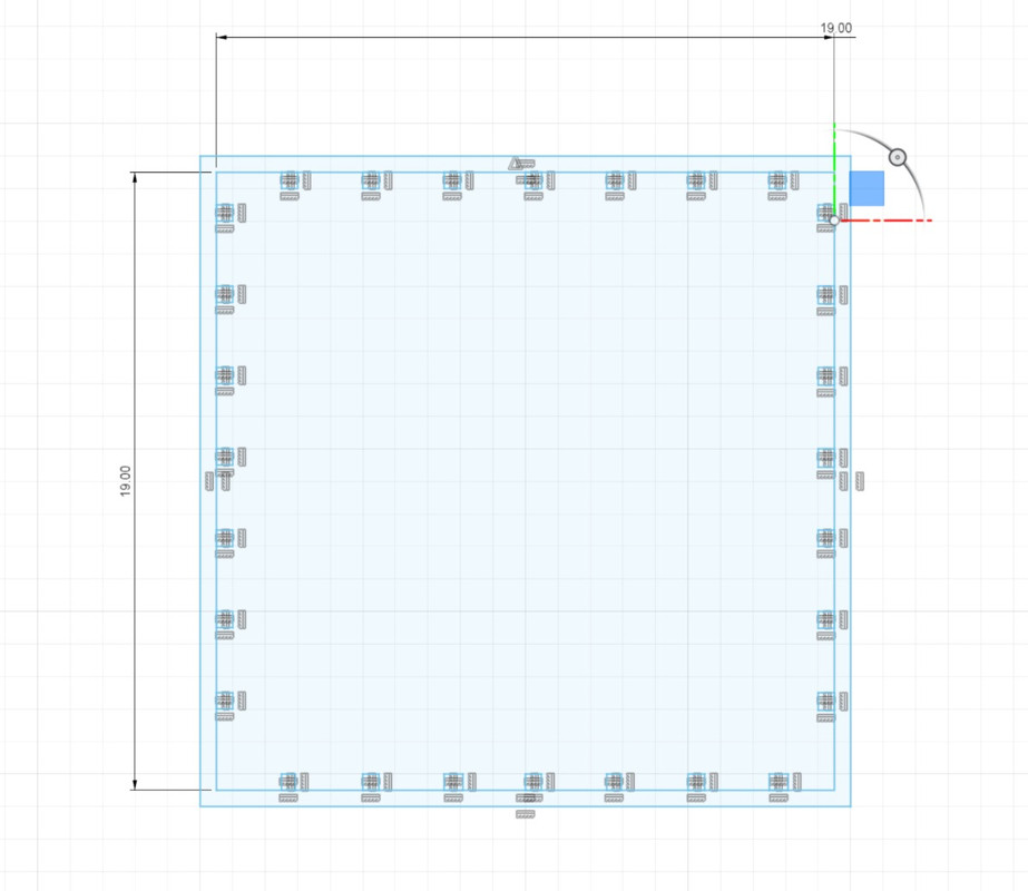
That I extrude too.
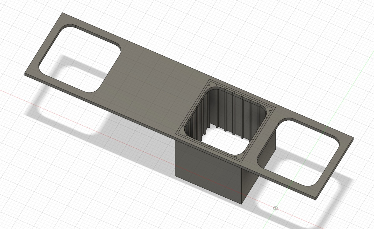
Then the horizontals, 5.
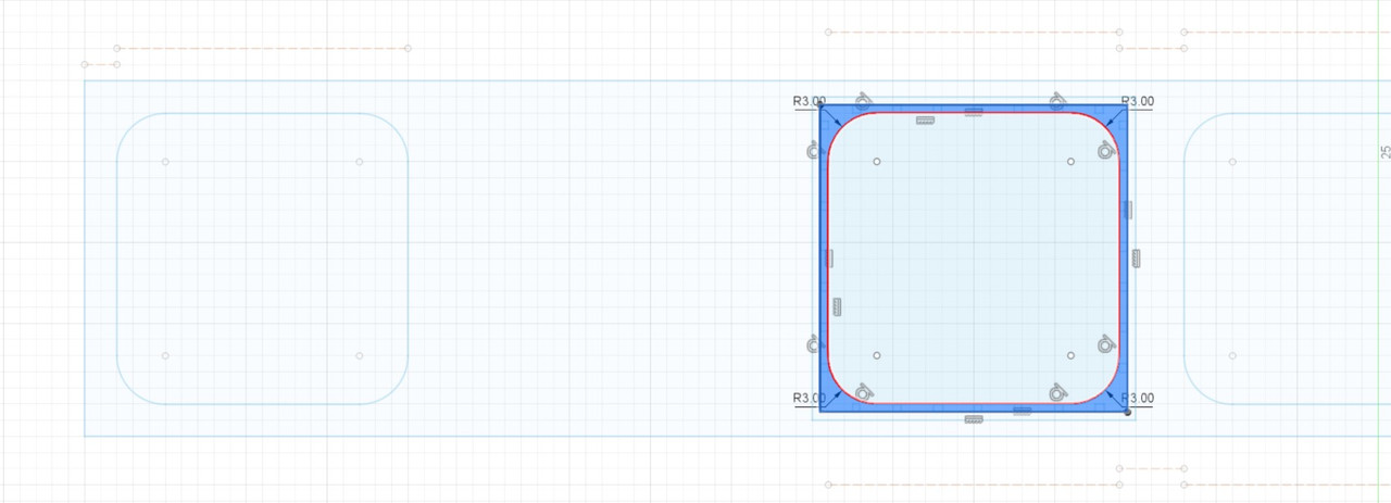
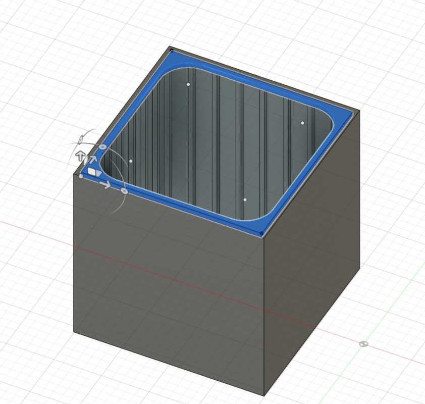
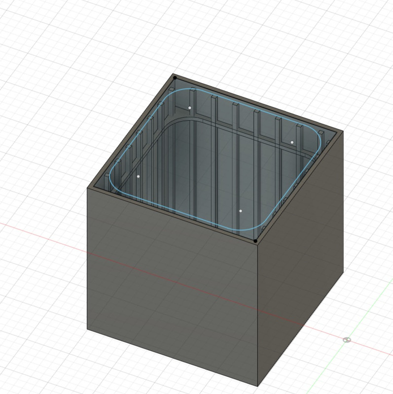
Then we do copy and paste, it goes fast.
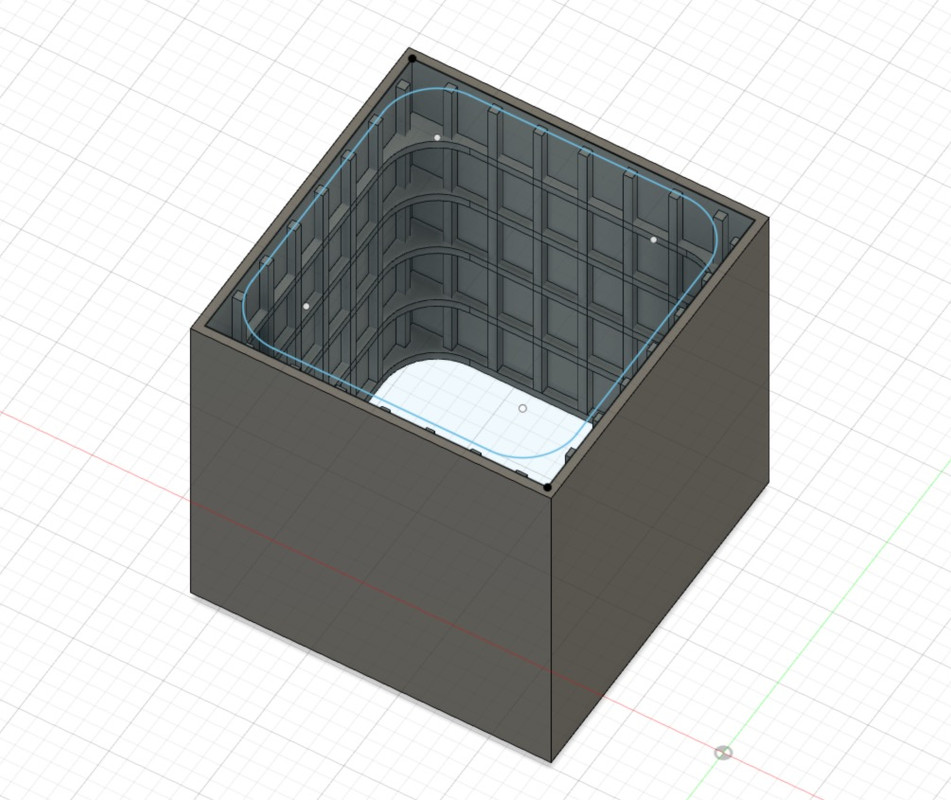
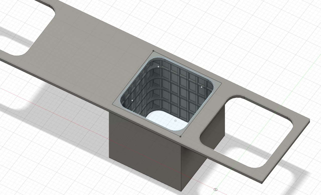
I create the first exhaust pipe, it is surrounded by insulation, probably asbestos at the time, confined with thin sheet metal. It's not done like that anymore of course, nowadays, we mainly use rock wool which resists well to high temperatures.
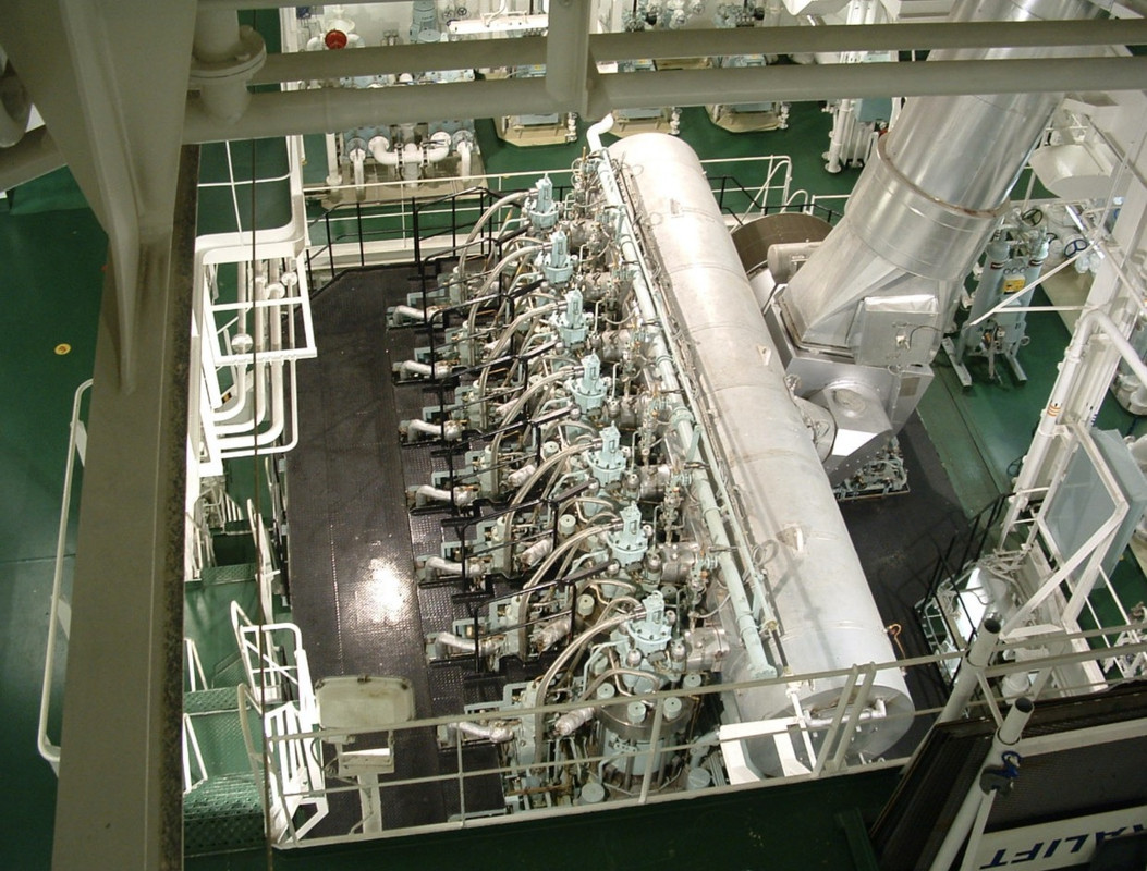
A bit like here on the exhaust outlet of the single turbocharger of this 14000 HP 2-stroke Burmeister B&W engine, the part with a larger diameter contains the expansion bellows with its mounting flanges. Personal photos.

Creation of the pipe, then its flange.
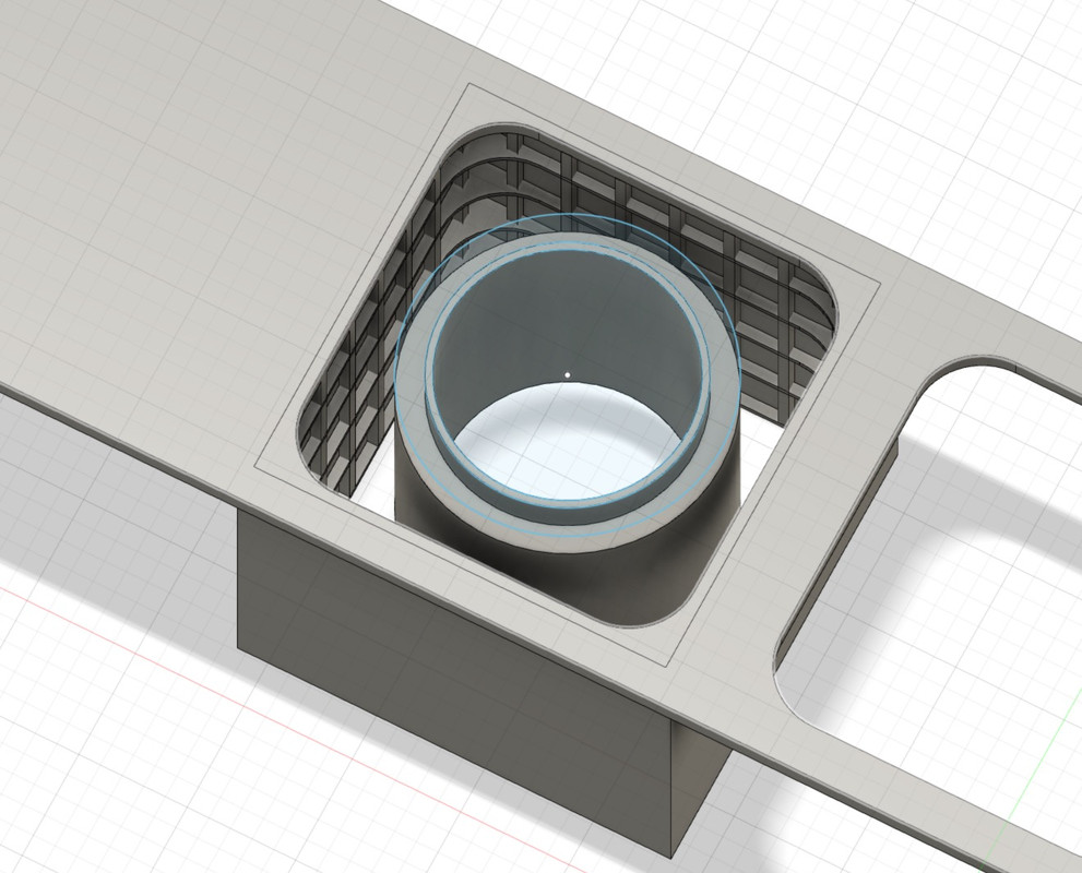
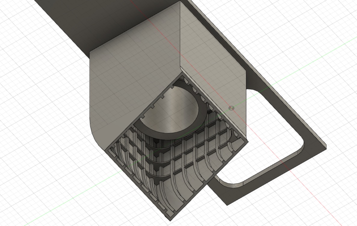
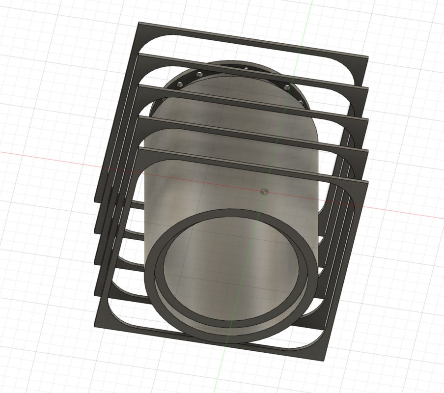
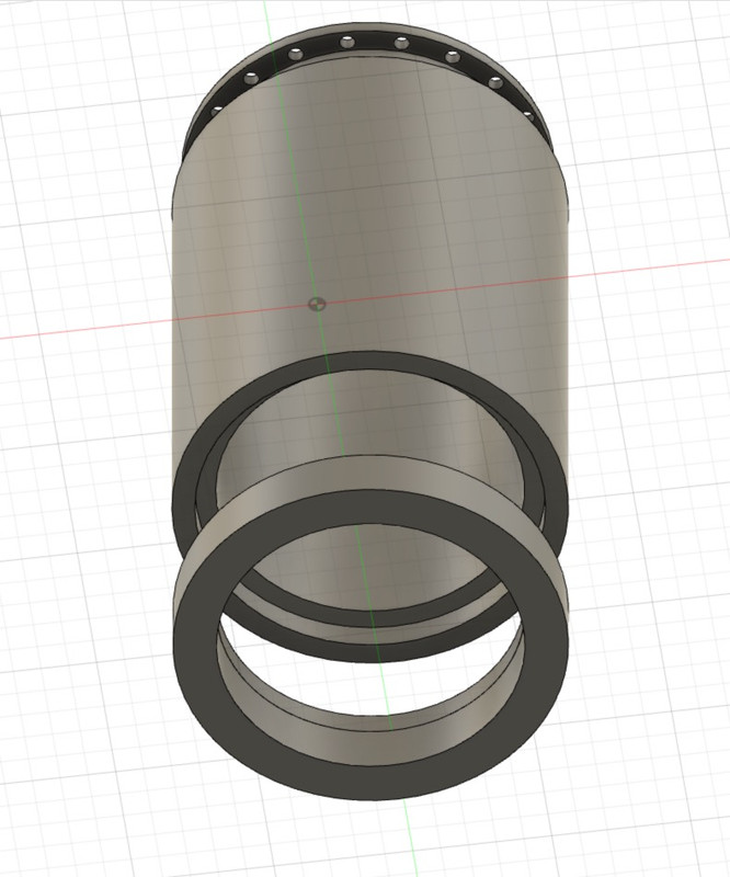
I built the pipe in two pieces that will fit together. Because it has to be easy to mount all this and above all it has to be painted in different colours. You always have to think about painting.
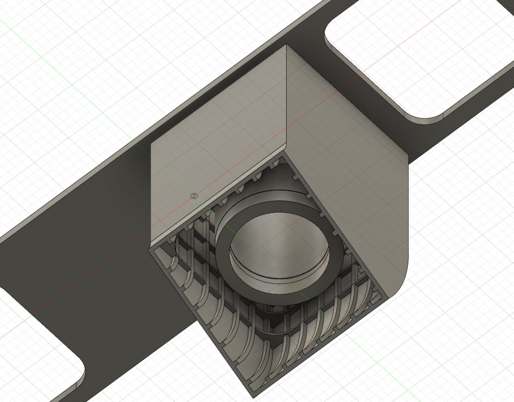
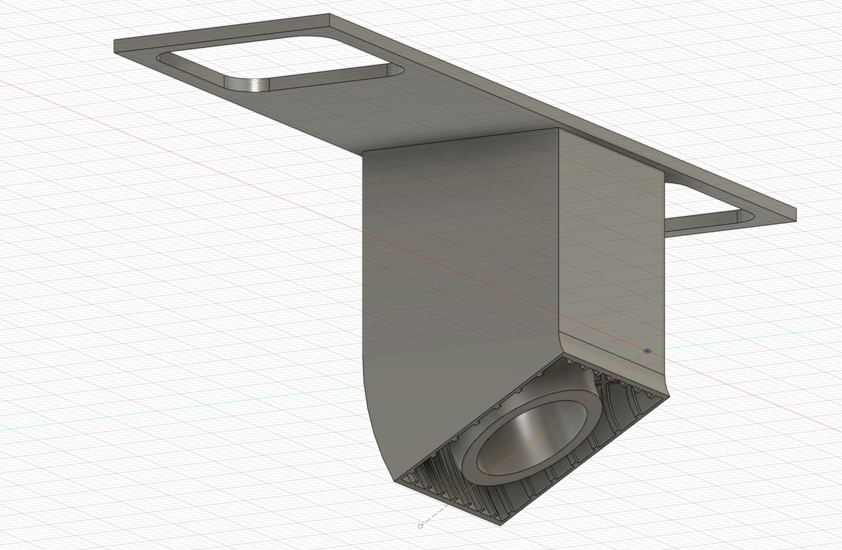
I extrude all this but by bending the shapes along a very precise axis and angle, that of the block.
I draw a construction line that will give me the position of the hangar floor thanks to the dimension in relation to the ceiling of the block, that's where I have to cut the casing and the pipe.
From there, I create a rectangular shape which will be used as a digital cutter, I will extrude this shape but in negative, all that will pass in its field will disappear, hence the red.
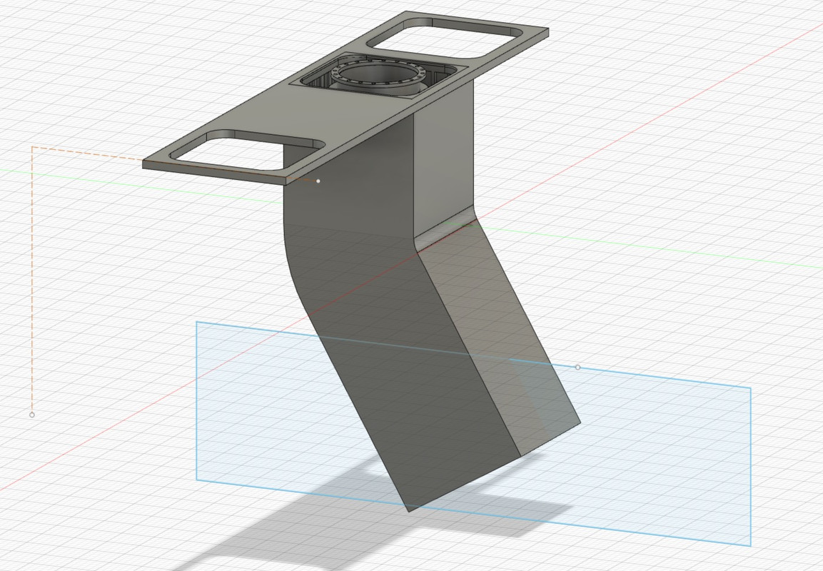
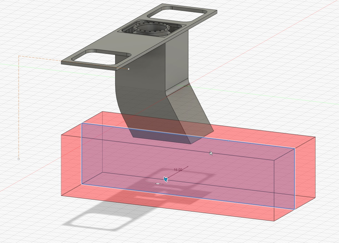
Well, that's almost done for this part. The pipe anchors still have to be installed in relation to the casing.
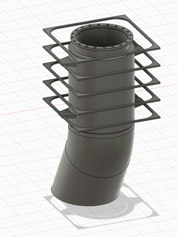
That's it, there's still the smallest pipe left to create and position in place.
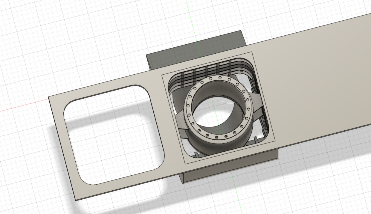
I make a copy and put it in the front slot.
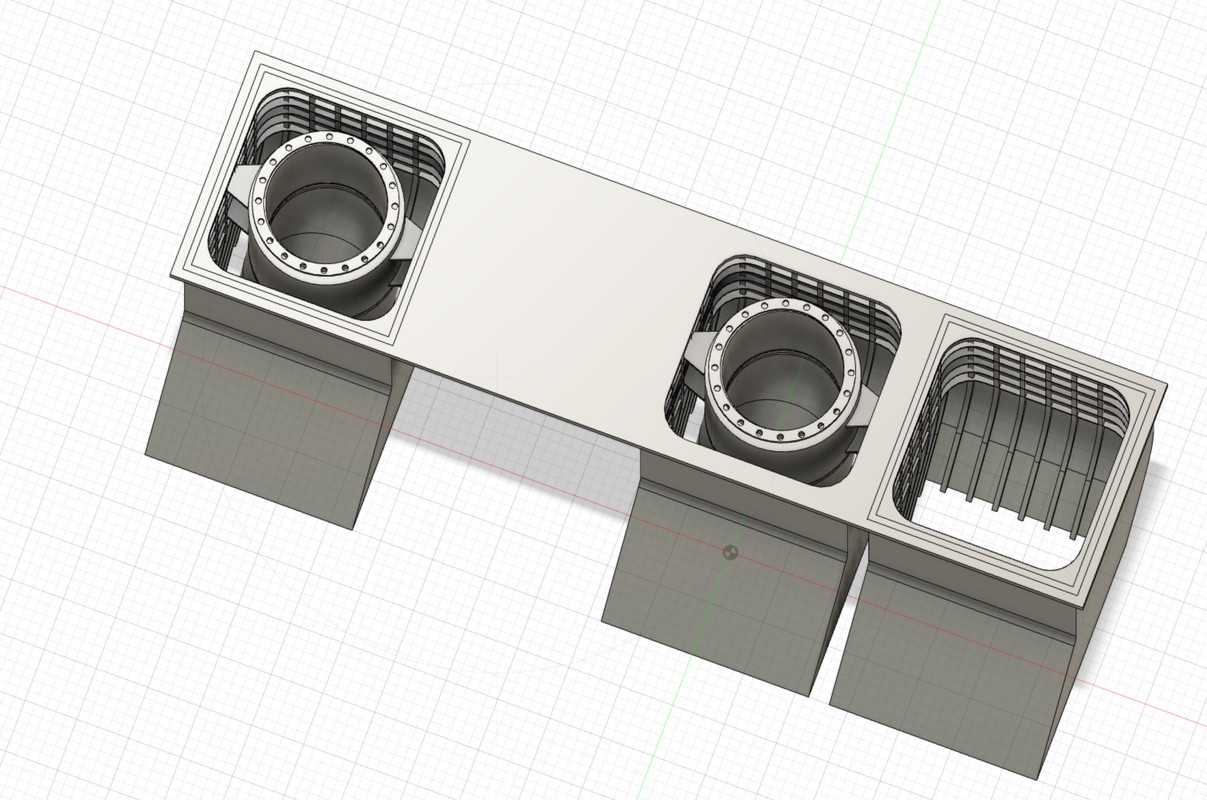
No need to rebuild a pipe, I reduce the size of the big one and adapt the junction with the shed floor.
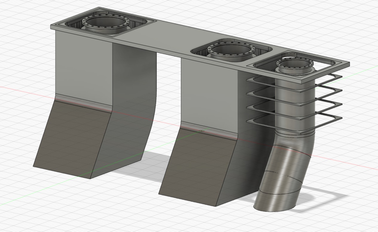
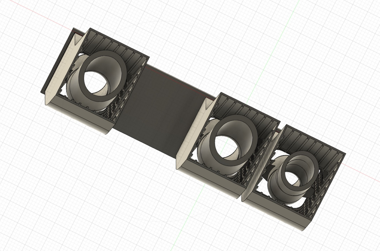
This time the module is complete, all the elements have to be saved in a .STL file in order to print them separately. Because each element will require a specific treatment for printing in terms of support.
The printing plate is well filled, the reinforcing brackets are in place.
We'll see the result in 3 hours...
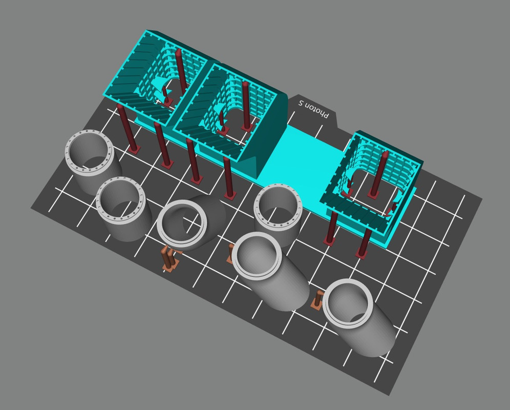
Printing It's not too bad, I had to re-drill the holes a bit because it's very small, with a 0.3 mm drill bit.
There is still the white paint to apply inside the ducts, white slightly yellowed compared to the white of the garage because of the heat.
I continued to furnish the central block, including the bomb and torpedo lift. There is the spare propeller rack to be created as well.
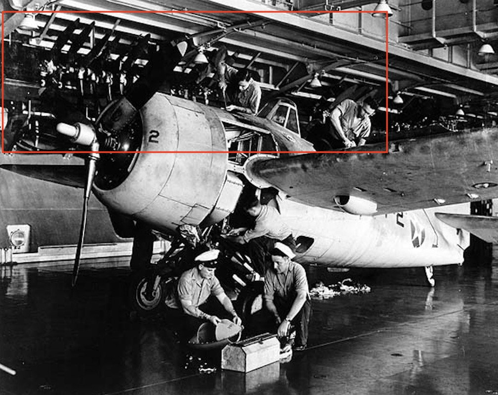
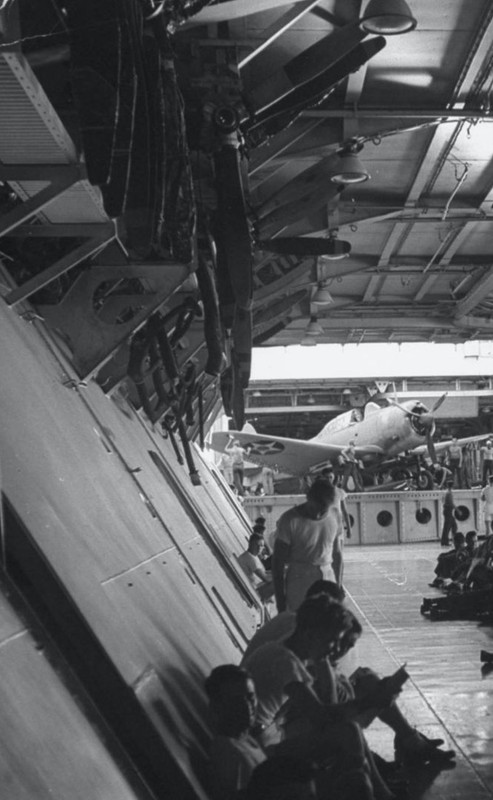
A good part of this block and the details I have added will not show because there is a garage ceiling accommodation on this level, they will be represented, cabins, offices, pilots briefing room, Admiral's cabin, Master's cabin etc..


Pascal
�Battleship Bretagne 3D: https://vu.fr/FvCY
�SS Delphine 3D: https://vu.fr/NeuO
�SS Nomadic 3D: https://vu.fr/tAyL
�USS Nokomis 3D: https://vu.fr/kntC
�USS Pamanset 3D: https://vu.fr/jXGQ
�Battleship Bretagne 3D: https://vu.fr/FvCY
�SS Delphine 3D: https://vu.fr/NeuO
�SS Nomadic 3D: https://vu.fr/tAyL
�USS Nokomis 3D: https://vu.fr/kntC
�USS Pamanset 3D: https://vu.fr/jXGQ
-
Fliger747
- Posts: 5068
- Joined: Wed Jan 02, 2013 1:15 am
Re: USS Hornet CV-8 Merit In 1/200 April 1942
Yes that is the Lundstrom book! The space between the flight deck support girders wasn't totally wasted. Many spare aircraft parts and even complete aircraft were hung from the overhead. Spares were a very important part of the USN ability to stay at sea and remain effective. I saw on the plans, but not in your model yet, the conflagration station. This fire fighting control booth was much larger on the ensuing Essex class ships, which could also isolate portions of the hangar deck.
Thank you for sharing your methods of working, very informative for those of us unfamiliar with this type of construction.
Cheers: Tom
Thank you for sharing your methods of working, very informative for those of us unfamiliar with this type of construction.
Cheers: Tom
-
Dennis78
- Posts: 40
- Joined: Wed Aug 31, 2011 5:52 am
Re: USS Hornet CV-8 Merit In 1/200 April 1942
Stunning research and design, I look forward to your progress.
- MartinJQuinn
- Posts: 8561
- Joined: Tue Jan 11, 2005 1:40 pm
- Location: New Jersey
Re: USS Hornet CV-8 Merit In 1/200 April 1942
My God. You are taking the detail to another stratosphere. Amazing.
Martin
"Tomorrow is the most important thing in life. Comes into us at midnight very clean. It's perfect when it arrives and it puts itself in our hands. It hopes we've learned something from yesterday." John Wayne
Ship Model Gallery
"Tomorrow is the most important thing in life. Comes into us at midnight very clean. It's perfect when it arrives and it puts itself in our hands. It hopes we've learned something from yesterday." John Wayne
Ship Model Gallery
- Iceman 29
- Posts: 1945
- Joined: Tue Sep 29, 2020 4:35 pm
- Location: Bretagne, France
Re: USS Hornet CV-8 Merit In 1/200 April 1942
Thanks to all!Fliger747 wrote:Yes that is the Lundstrom book! The space between the flight deck support girders wasn't totally wasted. Many spare aircraft parts and even complete aircraft were hung from the overhead. Spares were a very important part of the USN ability to stay at sea and remain effective. I saw on the plans, but not in your model yet, the conflagration station. This fire fighting control booth was much larger on the ensuing Essex class ships, which could also isolate portions of the hangar deck.
Thank you for sharing your methods of working, very informative for those of us unfamiliar with this type of construction.
Cheers: Tom
I believe I read that they later stopped attaching spare planes to the hangar ceilings because of the bombs that crossed the unarmoured flight deck and set these planes on fire, making the fire very difficult and dangerous to extinguish.
Pascal
�Battleship Bretagne 3D: https://vu.fr/FvCY
�SS Delphine 3D: https://vu.fr/NeuO
�SS Nomadic 3D: https://vu.fr/tAyL
�USS Nokomis 3D: https://vu.fr/kntC
�USS Pamanset 3D: https://vu.fr/jXGQ
�Battleship Bretagne 3D: https://vu.fr/FvCY
�SS Delphine 3D: https://vu.fr/NeuO
�SS Nomadic 3D: https://vu.fr/tAyL
�USS Nokomis 3D: https://vu.fr/kntC
�USS Pamanset 3D: https://vu.fr/jXGQ
- Iceman 29
- Posts: 1945
- Joined: Tue Sep 29, 2020 4:35 pm
- Location: Bretagne, France
Re: USS Hornet CV-8 Merit In 1/200 April 1942
Bunkering is one of the most important logistic parts.
https://www.wearethemighty.com/uss-neos ... belltitem2
USS Neosho (AO 23) refuels the carrier USS Yorktown (CV 5) before the Battle of the Coral Sea. (U.S. Navy)
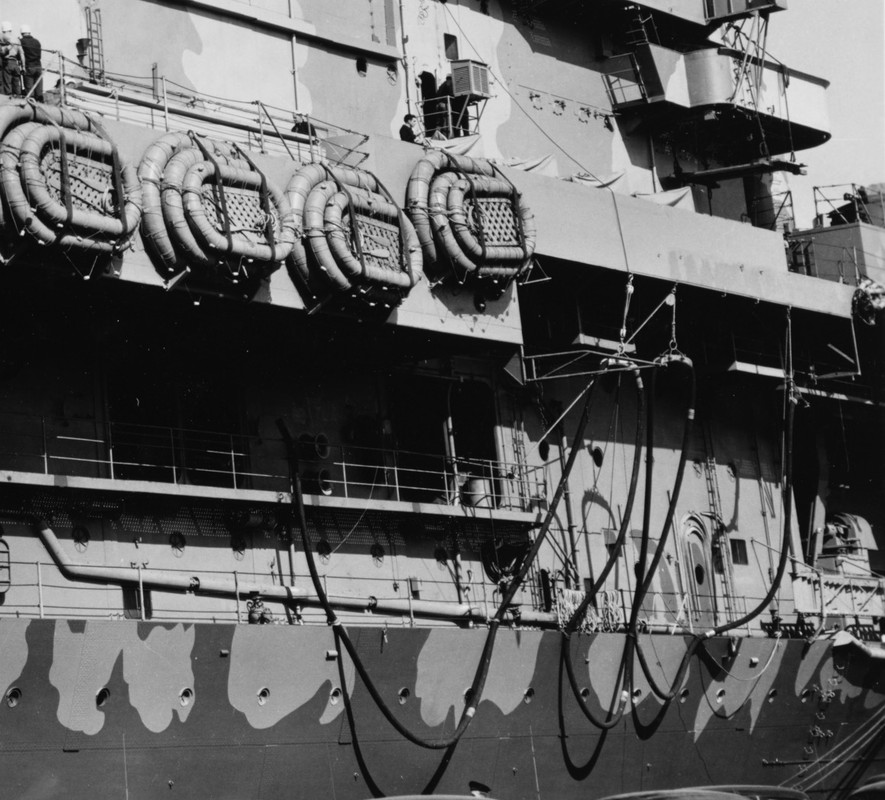
Hornet, bunkering hoses on starboard side.

USS Neosho (AO 23) will sink later..
The United States Navy fleet oiler USS Neosho (AO-23) is left burning and slowly sinking after an attack by Imperial Japanese Navy dive bombers on 7 May 1942 during the Battle of the Coral Sea.
https://www.delsjourney.com/uss_neosho/neosho_home.htm

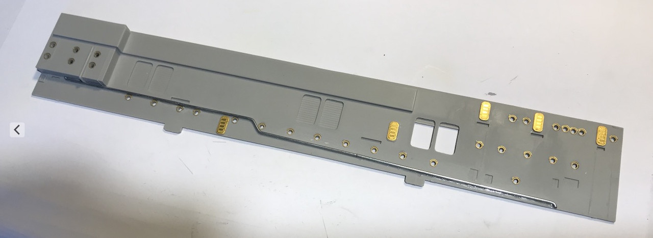
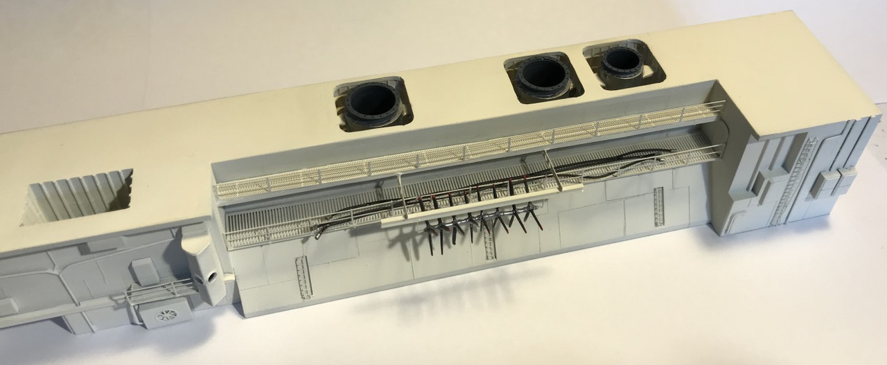
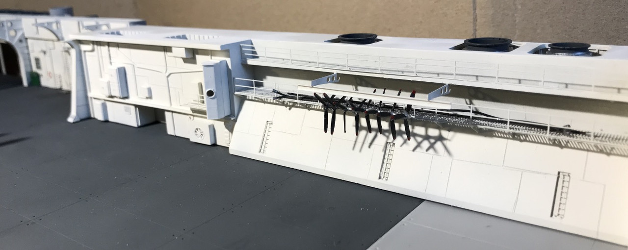
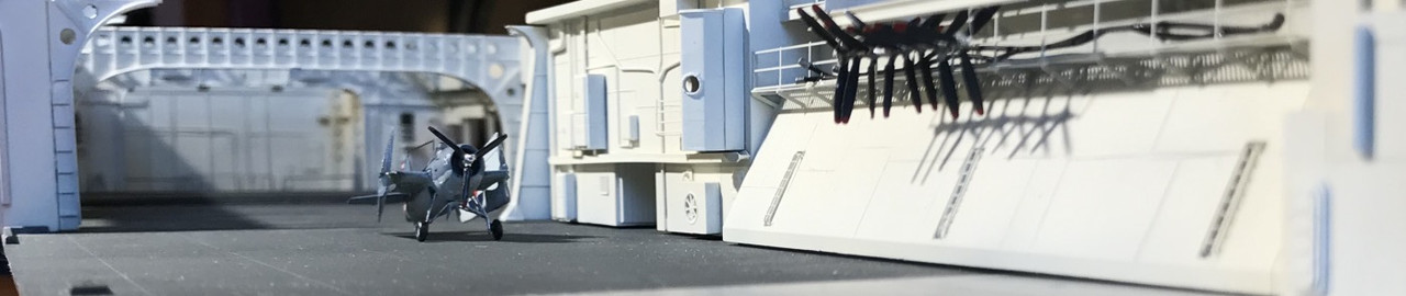
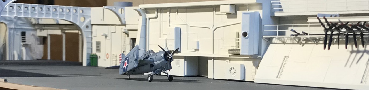
Some pictures of the painting of the central block. I pulled up the propeller rack when I saw a picture taken from another angle.
I had made a mistake.
Exterior bulkhead of the central block, we're just at the beginning of the detailing.

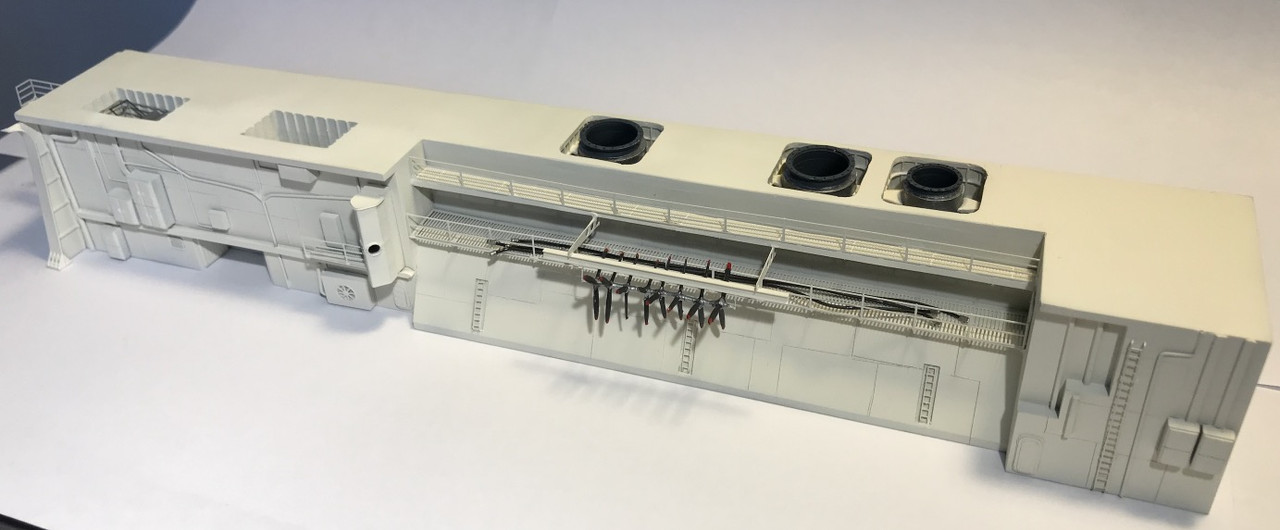
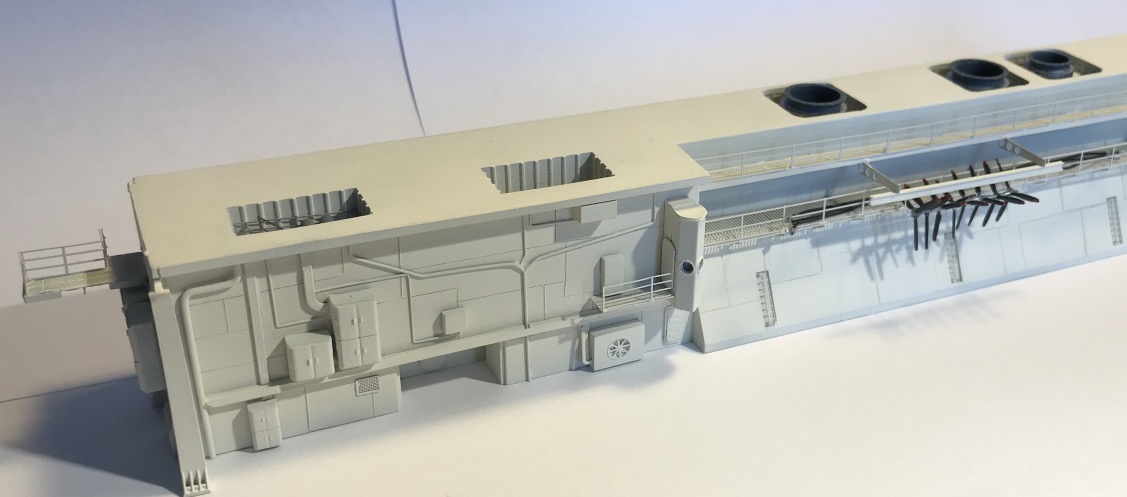
The central block is finished, maybe there are still some micro-decals to put.


I've been busy, this outer bulkhead has been a lot of work for me. It was fun to mount.
Putting up some decals, not sure if there was any, on the CV-12 yes, it doesn't matter.

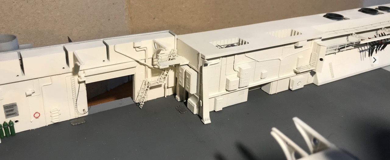
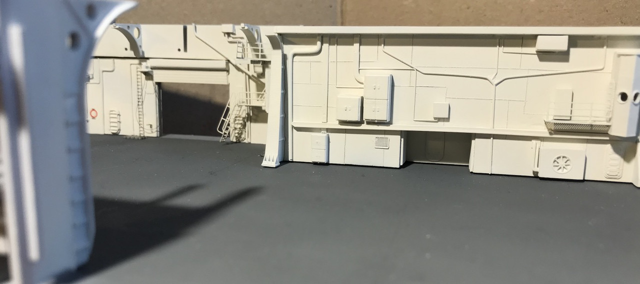
Exterior wall of the hangar under the island.
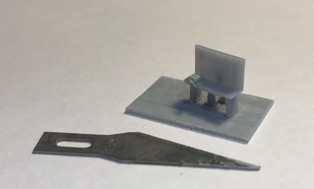
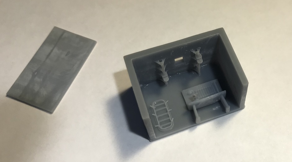
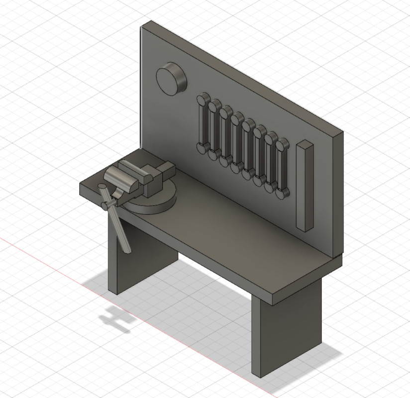
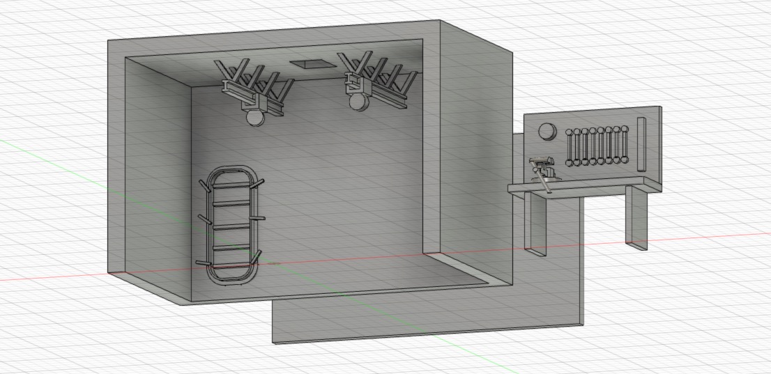
Manufacture of the small workshop that seems to be behind the curtains. There was lifeboats in this place at the beginning, removed later.
I let myself go on the details, it always gives me more experience for Fusion 360.
I installed lighting, it was worth it.
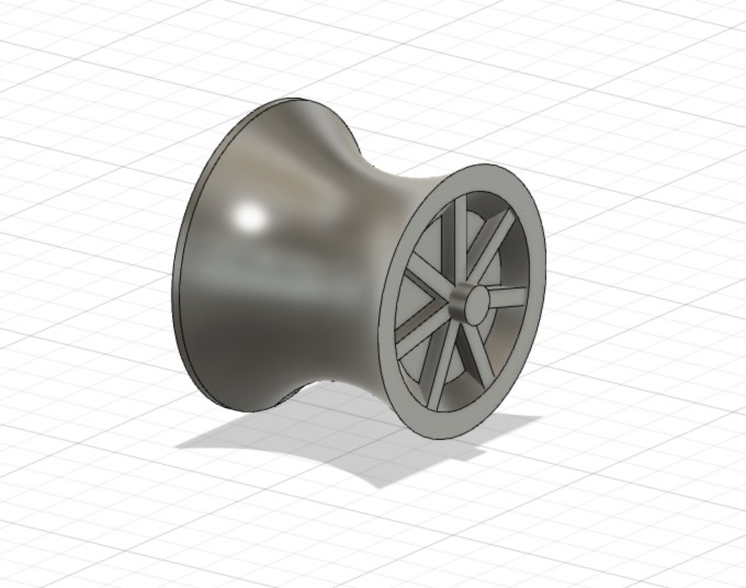
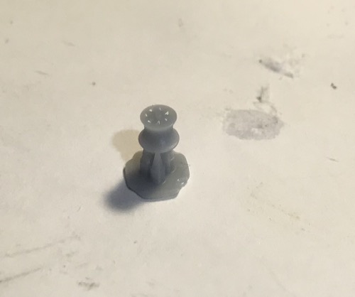
I made two warping drum for the winch that is on the bulkhead. These winches are used to handle the overboard refueling hose.
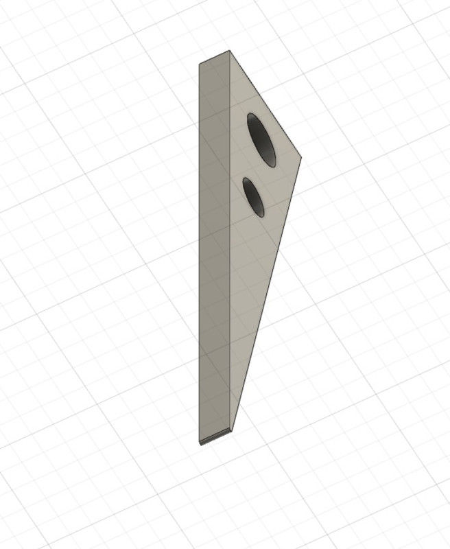
I had to add IPNs to fix the hose, as it is normally fixed to the flight deck, but as it will be removable, I had to find an alternative solution.


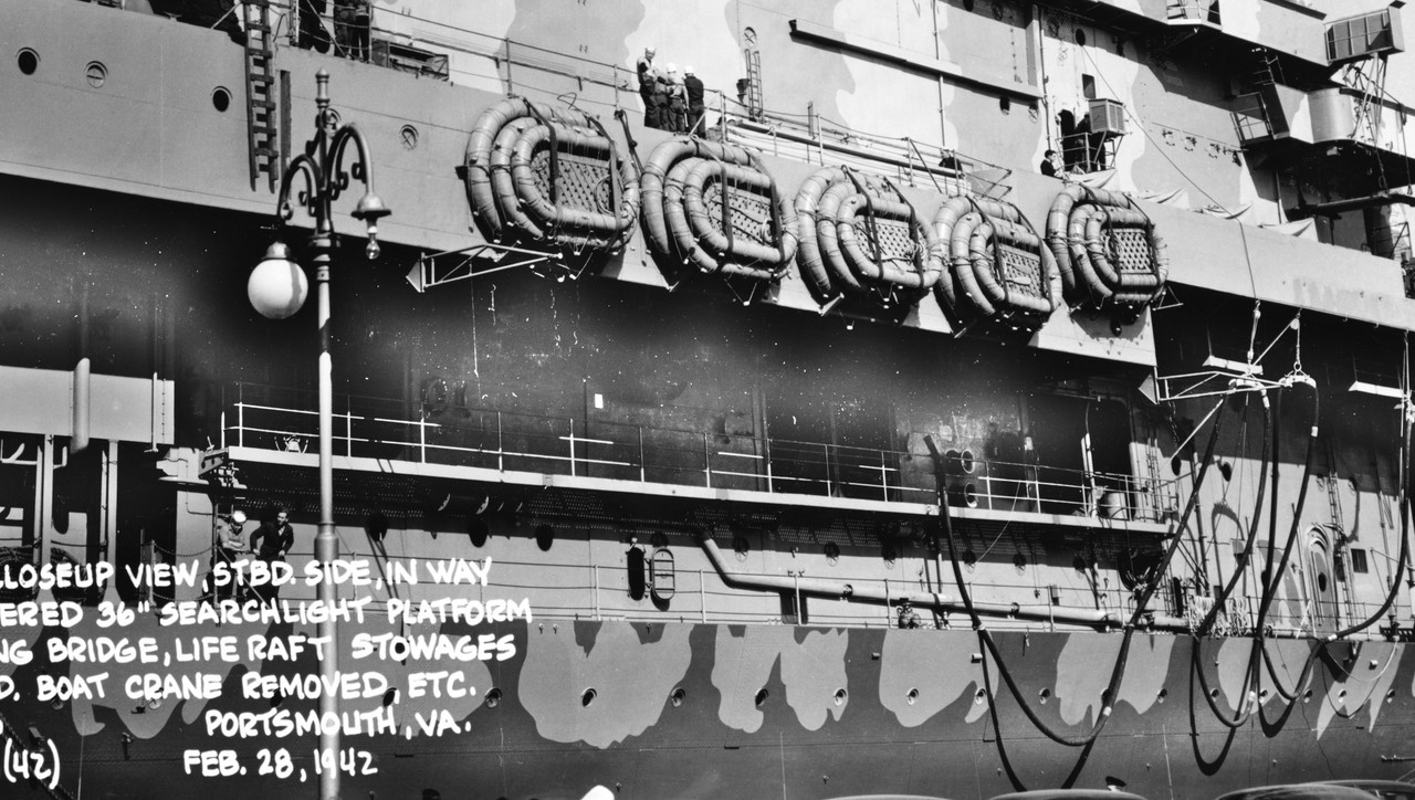
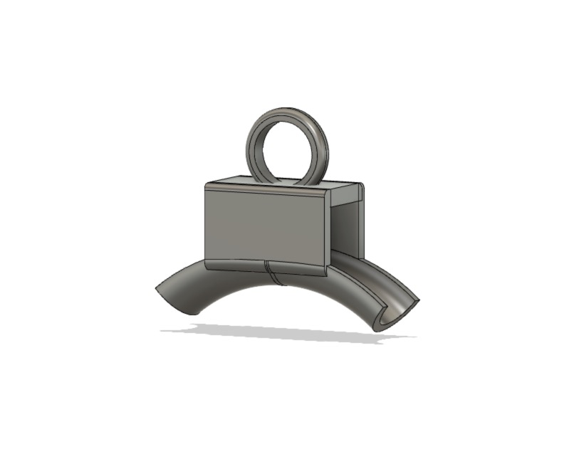
Manufacture of sea refuelling hose supports. Nothing is provided except the hose, nor explained...

I took care of the supply hose, I had free time as there is nothing on the Merit notice nor on the MK1 Design doc.
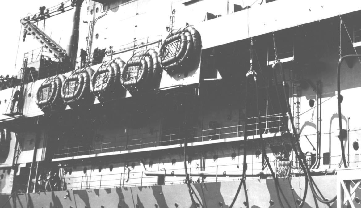
Luckily the two HD pictures taken in Portsmouth, USA, in February 1942 are really exceptional in quality, a little too much shadow because of the sun maybe, but by processing the image we can see some very interesting things.
The hoists are equipped with ropes and not with steel cables, it is certainly intended, it must be able to fuse quickly in case of untimely separation of the ships or something that goes wrong.
The aircraft carrier can also refuel other ships if needed. But when a tanker comes for bunkering, it's its equipment that's used.
"Raid Doolittle, fleet resupply operations, 1942. World War II.
Fleet of U.S. ships en route in the Pacific Ocean to launch the Doolittle bombing raid on Tokyo, Japan, at the beginning of World War II.
This plan focuses on the Fleet Oiler, USS Sabine, AO-25 and the USS Enterprise, CV-6.
From 01:38 to 01:44, the destroyer USS Benham, DD-397, is seen to starboard of the USS Sabine.
From 02:15 to 02:20, the fleet tanker USS Cimarron, AO-22, refuelling the heavy cruiser USS Northampton, CA-26 with a destroyer and the aircraft carrier USS Hornet, CV-8 in the background.
From time to time, between 0222 and 0245 hours, the tanker USS Cimarron, AO-22, approaches the USS Enterprise.
Location: Pacific Ocean. Date: 1942."
https://youtu.be/BzBXgcjDWq0
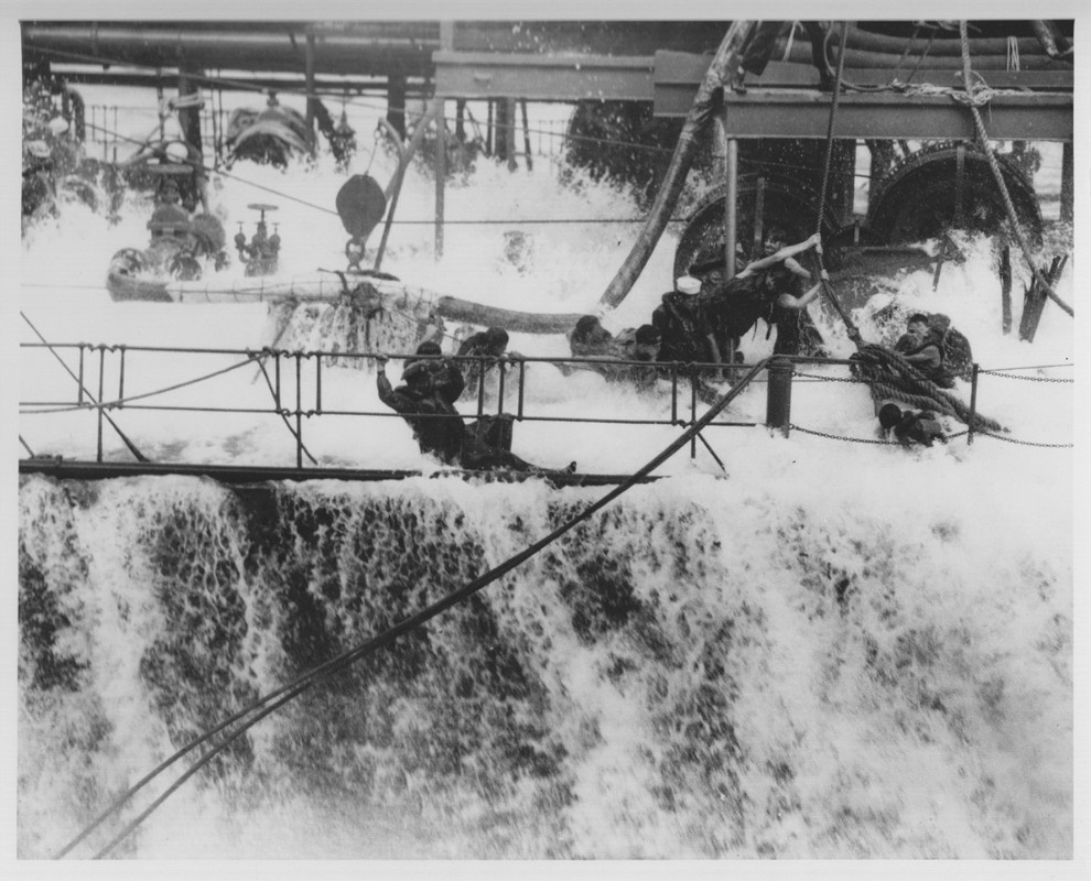
You can see on this picture that the main crane behind the island is used.

Being at the machine during my military service on a destroyer (D628 Vauquelin http://www.netmarine.net/bat/ee/vauqueli/index.htm ) in the early 80's, I took part in this kind of exercise on the deck, it's impressive. The chaplain was often lugged from ship to ship in this manner as well, I think he had to pray and rely on God during the short crossing.
The equipment is much performant to day:
https://youtu.be/Fz4F7EPCHhU
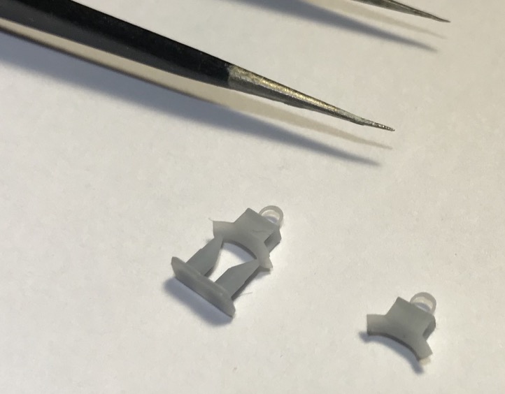
Missing pieces once printed.

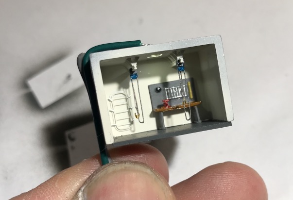
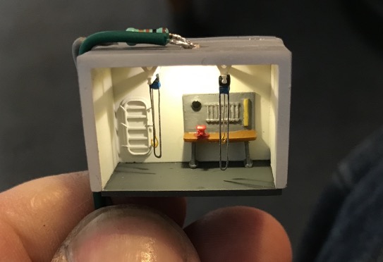
I added a 200 liters drum in the workshop..

The EZ line ends will be tighter once the deck is placed on the hull, with the hose moored to the rail. This is not possible at the moment.
I've tucked a copper wire into the black hose so that I can shape it perfectly to my liking and give it the right shape, otherwise it's impossible.

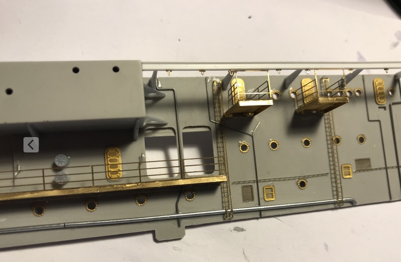
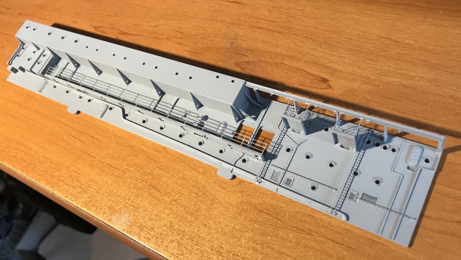
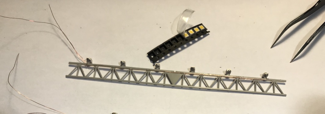
I am on the lighting of the front part of the hangar, soldering, wiring, it's tedious and not very interesting to present here for the moment, work on the line, more than 100 leds to equip:

https://www.wearethemighty.com/uss-neos ... belltitem2
USS Neosho (AO 23) refuels the carrier USS Yorktown (CV 5) before the Battle of the Coral Sea. (U.S. Navy)

Hornet, bunkering hoses on starboard side.

USS Neosho (AO 23) will sink later..
The United States Navy fleet oiler USS Neosho (AO-23) is left burning and slowly sinking after an attack by Imperial Japanese Navy dive bombers on 7 May 1942 during the Battle of the Coral Sea.
https://www.delsjourney.com/uss_neosho/neosho_home.htm

Some pictures of the painting of the central block. I pulled up the propeller rack when I saw a picture taken from another angle.
I had made a mistake.
Exterior bulkhead of the central block, we're just at the beginning of the detailing.

The central block is finished, maybe there are still some micro-decals to put.


I've been busy, this outer bulkhead has been a lot of work for me. It was fun to mount.
Putting up some decals, not sure if there was any, on the CV-12 yes, it doesn't matter.

Exterior wall of the hangar under the island.
Manufacture of the small workshop that seems to be behind the curtains. There was lifeboats in this place at the beginning, removed later.
I let myself go on the details, it always gives me more experience for Fusion 360.
I installed lighting, it was worth it.
I made two warping drum for the winch that is on the bulkhead. These winches are used to handle the overboard refueling hose.
I had to add IPNs to fix the hose, as it is normally fixed to the flight deck, but as it will be removable, I had to find an alternative solution.


Manufacture of sea refuelling hose supports. Nothing is provided except the hose, nor explained...

I took care of the supply hose, I had free time as there is nothing on the Merit notice nor on the MK1 Design doc.
Luckily the two HD pictures taken in Portsmouth, USA, in February 1942 are really exceptional in quality, a little too much shadow because of the sun maybe, but by processing the image we can see some very interesting things.
The hoists are equipped with ropes and not with steel cables, it is certainly intended, it must be able to fuse quickly in case of untimely separation of the ships or something that goes wrong.
The aircraft carrier can also refuel other ships if needed. But when a tanker comes for bunkering, it's its equipment that's used.
"Raid Doolittle, fleet resupply operations, 1942. World War II.
Fleet of U.S. ships en route in the Pacific Ocean to launch the Doolittle bombing raid on Tokyo, Japan, at the beginning of World War II.
This plan focuses on the Fleet Oiler, USS Sabine, AO-25 and the USS Enterprise, CV-6.
From 01:38 to 01:44, the destroyer USS Benham, DD-397, is seen to starboard of the USS Sabine.
From 02:15 to 02:20, the fleet tanker USS Cimarron, AO-22, refuelling the heavy cruiser USS Northampton, CA-26 with a destroyer and the aircraft carrier USS Hornet, CV-8 in the background.
From time to time, between 0222 and 0245 hours, the tanker USS Cimarron, AO-22, approaches the USS Enterprise.
Location: Pacific Ocean. Date: 1942."
https://youtu.be/BzBXgcjDWq0
You can see on this picture that the main crane behind the island is used.

Being at the machine during my military service on a destroyer (D628 Vauquelin http://www.netmarine.net/bat/ee/vauqueli/index.htm ) in the early 80's, I took part in this kind of exercise on the deck, it's impressive. The chaplain was often lugged from ship to ship in this manner as well, I think he had to pray and rely on God during the short crossing.
The equipment is much performant to day:
https://youtu.be/Fz4F7EPCHhU
Missing pieces once printed.

I added a 200 liters drum in the workshop..

The EZ line ends will be tighter once the deck is placed on the hull, with the hose moored to the rail. This is not possible at the moment.
I've tucked a copper wire into the black hose so that I can shape it perfectly to my liking and give it the right shape, otherwise it's impossible.

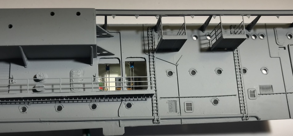
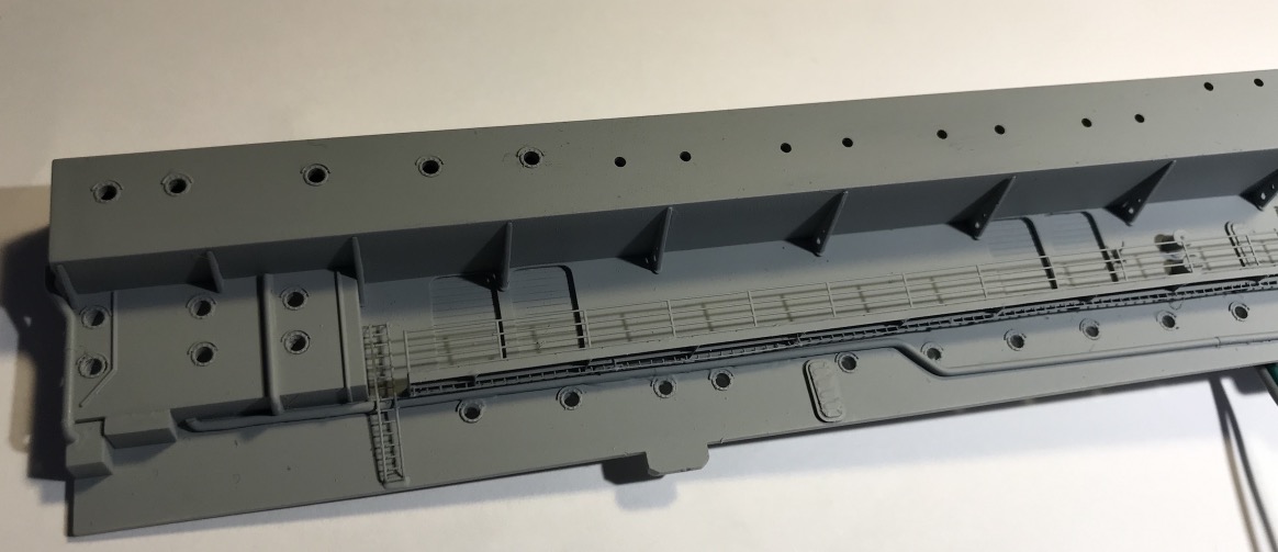
I am on the lighting of the front part of the hangar, soldering, wiring, it's tedious and not very interesting to present here for the moment, work on the line, more than 100 leds to equip:

Pascal
�Battleship Bretagne 3D: https://vu.fr/FvCY
�SS Delphine 3D: https://vu.fr/NeuO
�SS Nomadic 3D: https://vu.fr/tAyL
�USS Nokomis 3D: https://vu.fr/kntC
�USS Pamanset 3D: https://vu.fr/jXGQ
�Battleship Bretagne 3D: https://vu.fr/FvCY
�SS Delphine 3D: https://vu.fr/NeuO
�SS Nomadic 3D: https://vu.fr/tAyL
�USS Nokomis 3D: https://vu.fr/kntC
�USS Pamanset 3D: https://vu.fr/jXGQ
- gjholmes77
- Posts: 100
- Joined: Sun Jan 25, 2015 12:11 pm
- Location: Niceville, FL
Re: USS Hornet CV-8 Merit In 1/200 April 1942
Just when I'd thought that I'd seen it all. A 3d printed bench vice... on a workbench... in a shop... on a model ship.
Amazing stuff!
Amazing stuff!
- dhenning
- Posts: 352
- Joined: Sat Oct 05, 2013 1:32 pm
Re: USS Hornet CV-8 Merit In 1/200 April 1942
Wow! Amazing work and skill with the programs necessary for these delicate, detailed 3D prints!
- Iceman 29
- Posts: 1945
- Joined: Tue Sep 29, 2020 4:35 pm
- Location: Bretagne, France
Re: USS Hornet CV-8 Merit In 1/200 April 1942
Thanks to both of you! 
Pascal
�Battleship Bretagne 3D: https://vu.fr/FvCY
�SS Delphine 3D: https://vu.fr/NeuO
�SS Nomadic 3D: https://vu.fr/tAyL
�USS Nokomis 3D: https://vu.fr/kntC
�USS Pamanset 3D: https://vu.fr/jXGQ
�Battleship Bretagne 3D: https://vu.fr/FvCY
�SS Delphine 3D: https://vu.fr/NeuO
�SS Nomadic 3D: https://vu.fr/tAyL
�USS Nokomis 3D: https://vu.fr/kntC
�USS Pamanset 3D: https://vu.fr/jXGQ
- Jaguar
- Posts: 428
- Joined: Mon Jul 01, 2013 6:55 am
- Location: Usa
- Contact:
Re: USS Hornet CV-8 Merit In 1/200 April 1942
Amazing work Iceman. I can�t wait to see new pictures.
Jorge
Jorge
- Iceman 29
- Posts: 1945
- Joined: Tue Sep 29, 2020 4:35 pm
- Location: Bretagne, France
Re: USS Hornet CV-8 Merit In 1/200 April 1942
Thanks Jorge!
This project is on hold for the moment, I'm concentrating on my T2 tanker and I'm waiting for two new more performant 3D printers:
viewtopic.php?f=13&t=305869
This project is on hold for the moment, I'm concentrating on my T2 tanker and I'm waiting for two new more performant 3D printers:
viewtopic.php?f=13&t=305869
Pascal
�Battleship Bretagne 3D: https://vu.fr/FvCY
�SS Delphine 3D: https://vu.fr/NeuO
�SS Nomadic 3D: https://vu.fr/tAyL
�USS Nokomis 3D: https://vu.fr/kntC
�USS Pamanset 3D: https://vu.fr/jXGQ
�Battleship Bretagne 3D: https://vu.fr/FvCY
�SS Delphine 3D: https://vu.fr/NeuO
�SS Nomadic 3D: https://vu.fr/tAyL
�USS Nokomis 3D: https://vu.fr/kntC
�USS Pamanset 3D: https://vu.fr/jXGQ
-
Ian Roberts
- Posts: 314
- Joined: Sun Jan 08, 2012 4:59 pm
- Location: Austin
- Contact:
Re: USS Hornet CV-8 Merit In 1/200 April 1942
Truly incredible work!
-
Dadeo911
- Posts: 77
- Joined: Sun Nov 04, 2012 12:42 pm
- Location: Landlocked in The Great White North
Re: USS Hornet CV-8 Merit In 1/200 April 1942
This is some truly inspirational work. Wow doesn't even come close to covering it.
How are you wiring the LEDs for the girders in the Hanger?
Keep up the good work. I am eagerly awaiting your next update.
Cheers,
Chris
How are you wiring the LEDs for the girders in the Hanger?
Keep up the good work. I am eagerly awaiting your next update.
Cheers,
Chris
- Iceman 29
- Posts: 1945
- Joined: Tue Sep 29, 2020 4:35 pm
- Location: Bretagne, France
Re: USS Hornet CV-8 Merit In 1/200 April 1942
Thank you Chris,
I'm going to supply them with 12 volts, they are connected in series by 5 or 6 leds and a common resistor.The value of the resistor is adapted to provide a yellow light and a reasonable number of milli amperes.
I have other projects in progress, so the Hornet is on stand by.
I'm going to supply them with 12 volts, they are connected in series by 5 or 6 leds and a common resistor.The value of the resistor is adapted to provide a yellow light and a reasonable number of milli amperes.
I have other projects in progress, so the Hornet is on stand by.
Pascal
�Battleship Bretagne 3D: https://vu.fr/FvCY
�SS Delphine 3D: https://vu.fr/NeuO
�SS Nomadic 3D: https://vu.fr/tAyL
�USS Nokomis 3D: https://vu.fr/kntC
�USS Pamanset 3D: https://vu.fr/jXGQ
�Battleship Bretagne 3D: https://vu.fr/FvCY
�SS Delphine 3D: https://vu.fr/NeuO
�SS Nomadic 3D: https://vu.fr/tAyL
�USS Nokomis 3D: https://vu.fr/kntC
�USS Pamanset 3D: https://vu.fr/jXGQ
-
anyahajobuzi
- Posts: 374
- Joined: Mon Oct 19, 2009 2:56 am
- Location: Whitehorse, Yukon, Canada, North pole
Re: USS Hornet CV-8 Merit In 1/200 April 1942
Well, you are obviously insane. And I mean that in the best possible form of a compliment. And you are channeling your craziness into something truly amazing! Beautiful work!!! Too bad very little will be seen after the deck is installed....
Keep it up!
Laci
Keep it up!
Laci
- Iceman 29
- Posts: 1945
- Joined: Tue Sep 29, 2020 4:35 pm
- Location: Bretagne, France
Re: USS Hornet CV-8 Merit In 1/200 April 1942
Tks Laci!
The flight deck will be easily removable. It's planned.
Pascal
�Battleship Bretagne 3D: https://vu.fr/FvCY
�SS Delphine 3D: https://vu.fr/NeuO
�SS Nomadic 3D: https://vu.fr/tAyL
�USS Nokomis 3D: https://vu.fr/kntC
�USS Pamanset 3D: https://vu.fr/jXGQ
�Battleship Bretagne 3D: https://vu.fr/FvCY
�SS Delphine 3D: https://vu.fr/NeuO
�SS Nomadic 3D: https://vu.fr/tAyL
�USS Nokomis 3D: https://vu.fr/kntC
�USS Pamanset 3D: https://vu.fr/jXGQ
-
propmeup1
Re: USS Hornet CV-8 Merit In 1/200 April 1942
Besides myself I think your the only one I've yet to see make the aux elevators. Thank you for taking the time to do that. 1:350 here but it makes a difference and don't let no one tell you it's a waist of time.
Keith
Keith
- silvershadow
- Posts: 283
- Joined: Mon Nov 04, 2013 2:17 am
- Location: _/\/�����\/\_ Cape Town
Re: USS Hornet CV-8 Merit In 1/200 April 1942
Love your work, well done, you're a very talented modeller!! two thumbs up!!
Last edited by silvershadow on Mon Dec 07, 2020 7:31 am, edited 1 time in total.
Jacques
_________________
Currently working on:
1/350 CVN 65 - Project Enterprise
viewtopic.php?f=59&t=210966
_________________
Currently working on:
1/350 CVN 65 - Project Enterprise
viewtopic.php?f=59&t=210966