Looking for Bismark Solidworks or Delftship Hull
Moderator: ArizonaBB39
-
rtwpsom2

- Posts: 1438
- Joined: Tue Aug 19, 2008 10:15 pm
- Location: State of Denial
Re: Looking for Bismark Solidworks or Delftship Hull
Keep in mind that it is always best practice to have the same number and types of entities in loft sections. For instance if you first section goes arc-line-arc, then you should try to make sure all your sections go arc-line-arc, even if that means you need to make that line segment only .001" in one of the sections.
-
proflooney
- Posts: 213
- Joined: Fri Nov 12, 2010 3:19 pm
- Location: Moline Illinois
- Contact:
Re: Looking for Bismark Solidworks or Delftship Hull
yea most of my stuff is almost exclusively splines. I know they also say you should have the same number of points in each spline too but thats hard to do on some shapes and to keep the shape you need
Joe
Joe
-
rtwpsom2
- Posts: 1438
- Joined: Tue Aug 19, 2008 10:15 pm
- Location: State of Denial
Re: Looking for Bismark Solidworks or Delftship Hull
No, in Solidworks that isn't necessary since you can control connection points in the loft manager. However if you are connecting the loft sections with a lot of guide curves, having the same number of spline points makes it easier to draw the guide curves. But SolidWorks doesn't need that. AutoCAD you absolutely need that.
-
proflooney
- Posts: 213
- Joined: Fri Nov 12, 2010 3:19 pm
- Location: Moline Illinois
- Contact:
Re: Looking for Bismark Solidworks or Delftship Hull
Ok thanks. and the moving of those little green guide points doesnt always work lol I have had times I couldnt get them to line up so had to do a loft in segments (which I hate)
Joe
Joe
-
rtwpsom2
- Posts: 1438
- Joined: Tue Aug 19, 2008 10:15 pm
- Location: State of Denial
Re: Looking for Bismark Solidworks or Delftship Hull
If you have problems with them, then guide curves are the answer. Lots of them lower down, fewer higher up. You can add horizontal planes and add lines between the vertical hull lines. The only problem with doing that near the stern where it is raised up off the baseline. For those I make 3D splines but you have to work extra hard to make sure they adhere to the line of the hull you want to follow. I make all the forward spline points adhere to the plane, but use dims to constrain the ones further aft where they need to be higher up. Hope you can figure out what I am saying there.
-
proflooney
- Posts: 213
- Joined: Fri Nov 12, 2010 3:19 pm
- Location: Moline Illinois
- Contact:
Re: Looking for Bismark Solidworks or Delftship Hull
Yea I know what yer saying. I tried using the waterlines as guides but they are so far off they are useless from the ones I have played with.
also I do have a question on guides like the waterlines. If I am doing a loft it seems if my guide doesnt intersect with EVERY station I get an error. is there a way to use short guides when lofting that only intersect a few stations but not all of them?
Joe
also I do have a question on guides like the waterlines. If I am doing a loft it seems if my guide doesnt intersect with EVERY station I get an error. is there a way to use short guides when lofting that only intersect a few stations but not all of them?
Joe
-
rtwpsom2
- Posts: 1438
- Joined: Tue Aug 19, 2008 10:15 pm
- Location: State of Denial
Re: Looking for Bismark Solidworks or Delftship Hull
No, unfortunately they need to intersect with every loft section. This is one area I wish they would change/fix. We should be able to use a local guide curve in some places where we need to control loft better, but I haven't seen any evidence they plan to change it. The only solution for a hull is to plan out every single guide curve so you know it will follow the entire contour. In order to make the entire side of the hull a single surface I actually start and end my loft on the front plane, while all my waterlines are parallel to the right plane. In other words, the profile of the bow is where I start, then I use guide curves to constrain the loft through the water lines, and end at the stern profile line. It takes a lot of work, but I get a really high quality model when I am done. And if you want to have a perfectly smooth hull without having to play with the lines, you need to find the table of offsets for the hull. My latest project is huge but I have the table of offsets for the hull and I didn't have to smooth the hull out any. They only things I had to play with were those 3D splines near the back I talked about earlier.
-
proflooney
- Posts: 213
- Joined: Fri Nov 12, 2010 3:19 pm
- Location: Moline Illinois
- Contact:
Re: Looking for Bismark Solidworks or Delftship Hull
ok I have a couple tables of offsets but never had much luck setting them up in SW. but the good thing abt having them is that I been able to learn how to use them to come up with the curves. ie how to convert the numbers to coordinates
Joe
Joe
-
rtwpsom2
- Posts: 1438
- Joined: Tue Aug 19, 2008 10:15 pm
- Location: State of Denial
Re: Looking for Bismark Solidworks or Delftship Hull
They really do provide a better hull surface over the line drawings which may be skewed or warped. I make a grid on the right plane using the verticals and horizontals from the tables. Then on each plane I use lines and splines to make the hull lines like normal. Because most of the bottom of the hull is flat I always make the bottom most entity a line, even if it is only an 1/2" long back near the stern. That makes it a lot easier. Then I add splines above that and dimension them from tables. I have a predetermined height that all my hull lines go to. It is usually about a meter above the tip of the bow. When you surface you always want to make your surface go well past the edge point, because that will make it a thousand times easier to trim all the surfaces later. Also, keep in mind that just because you used the table, the splines will not always adhere to the curve the way you want. It is important that you use every single dimension from the table, and even then sometimes up by the bow you will need to play with their handles to get them to fall into line. Once you are done with a spline, the last thing you need to do is click on it and go over in the properties manager click on reset all handles. This might change a handle you moved, but it will relax all the other ones. Fix the moved handles and you should be good.
P.S. I will be out of range of the internet for a few days so keep posting questions and I will answer them as soon as I get back. Good luck.
P.S. I will be out of range of the internet for a few days so keep posting questions and I will answer them as soon as I get back. Good luck.
-
proflooney
- Posts: 213
- Joined: Fri Nov 12, 2010 3:19 pm
- Location: Moline Illinois
- Contact:
Re: Looking for Bismark Solidworks or Delftship Hull
thanks rob. the solidworks users group shpowed me a cool site called join.me which allows me to share my computer screen in real time if i get to a point where im really having probs. I went yesterday and grabbed that book on surfaces you mentions and started reading it last night. which was a fun night. neighbor building is 10 ft from my house and caught fire so I called 911. seems was a meth lab that caught fire so we had city cops, county cops, state police, csi, swat, fire dept, and the military arsenal heres decon unit here from 4 pm til 1 am and abt 9 pm they kicked me out of the house for 3 hrs while they removed the cook as they were worried abt explosion since it was still working. was a really fun night lol. I think I got to chapter 3 I am actually reading the book not just bouncing to the tutorials so I can try to learn how to do surface modeling since seems like once i do ship hulls should be as easy as aircraft fusses are with solid lofting.
thanks for the tip on the book its lot easier to understand suirfacing than whats in the bible
joe
thanks for the tip on the book its lot easier to understand suirfacing than whats in the bible
joe
-
DrPR

- Posts: 1689
- Joined: Sun Mar 07, 2010 12:01 am
- Location: Corvallis, Oregon, USA
- Contact:
Re: Looking for Bismark Solidworks or Delftship Hull
This is an interesting discussion. I, too, have found the Table of Offsets to be much more reliable than the hull cross section lines in drawings.
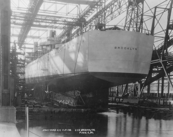
However, even the Table of Offsets may not be sufficient to model parts of the hull that have extreme variations over short distances. For example, on the Cleveland class hull the stern "transom" is squared off at the bottom like the Brooklyn class, but rounded at the main deck level. A sharp knuckle runs most of the length of the hull, but near the stern the hull surface is a smooth curve from the vertical sides to the bottom of the hull near the stern. But at the stern this smooth curve transitions suddenly into the very sharp knuckle at the bottom of the transom. There are compound curves everywhere!
None of this detail at the stern is in the Table of Offsets - only wide spaced section lines and a few butt lines at the stern are included. To make matters worse, in the original blueprints three different drawings exist showing the shape of the stern, showing three different shapes!
Eventually I made an important discovery while looking through the blueprints. One of the entries in the microfilm Index was "Mold Loft Offsets" - 81 sheets. In these were dozens of tables called "Shell Sight Edges." These were like the Table of Offsets, but they listed the edges of the hull plating strakes, giving the shape of individual hull plates! These gave the precise curvature of the plating as it wrapped around from the side to the stern. Coincidentally, these tables agreed very closely to one of the three drawings.
My guess is that the mold loft used these tables to form the curvature of the hull plates before they were attached to the ship. I also suspect these tables were used to "survey" the positions of the plates as they were lowered into place on the support framing as the hull was being constructed. Precise positioning was important because the plating was put in place first and then the interior framing and longitudinals were constructed inside it.
However, there was still a small area at the outboard bottom of the transom that wasn't described in any of the tables or drawings. At this point the shipyard just did whatever was necessary to join the plating. I guess the only way I will ever find out what that actually looked like is to wait until the USS Little Rock museum ship is in drydock and go there to measure it myself!
A collision at sea will ruin your entire day. Aristotle
-
proflooney
- Posts: 213
- Joined: Fri Nov 12, 2010 3:19 pm
- Location: Moline Illinois
- Contact:
Re: Looking for Bismark Solidworks or Delftship Hull
I been working on my Broolyn class this evening and it has some baffeling lines. its the usual slow curve at the bottom going to vertical sides but then from the part where it angles up to the transom there is a sharp edge up to the transom area but then the transom area has a nice radius in it. so it goes slow curve sharm edge small radius really weird
joe
PS oh thats yer handle P lol i was curious what yer handle was
joe
PS oh thats yer handle P lol i was curious what yer handle was
-
proflooney
- Posts: 213
- Joined: Fri Nov 12, 2010 3:19 pm
- Location: Moline Illinois
- Contact:
Re: Looking for Bismark Solidworks or Delftship Hull
Well it started out looking good but that stern I just dont like it. I think one of my profiles needs adjusted but it still doesnt look right
Joe
Joe
- Attachments
-
-
-
proflooney
- Posts: 213
- Joined: Fri Nov 12, 2010 3:19 pm
- Location: Moline Illinois
- Contact:
Re: Looking for Bismark Solidworks or Delftship Hull
Ok I got the crease where I am happy but the thing bottering me is the bottom goes from radius to flat to flat with radius and it just doesnt look right. then again I am new to ships so I wouldnt know if it was right or wrong by lookng at it like i would be able to do with planes
Joe
Joe
- Attachments
-
-
DrPR
- Posts: 1689
- Joined: Sun Mar 07, 2010 12:01 am
- Location: Corvallis, Oregon, USA
- Contact:
Re: Looking for Bismark Solidworks or Delftship Hull
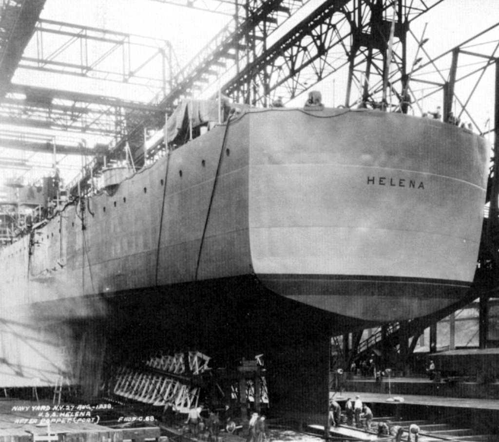
The "crease" is called a "knuckle" in ship terms. There are several very good photos of Brooklyn sterns on Navsource. Here are two:
http://www.navsource.org/archives/04/040/0404022.jpg
http://www.navsource.org/archives/04/050/0405025.jpg
It looks like the knuckle in the hull plating actually extended almost to the bow of the ship. The armor belt was attached to the outside of the hull plating and hid much of the knuckle.
Just forward of the stern the stern the knuckle disappears and the hull plating curves smoothly from the vertical sides to the bottom. The stern of the ship was a slightly curved transom with knuckles all around (sides and bottom).
A collision at sea will ruin your entire day. Aristotle
-
proflooney
- Posts: 213
- Joined: Fri Nov 12, 2010 3:19 pm
- Location: Moline Illinois
- Contact:
Re: Looking for Bismark Solidworks or Delftship Hull
Well I got the flow going better but I keep getting a bulge at one area. all the sides are straight and there is a former right in the center of the bulge. it flows nicely with the rest of the hull but for some reason deforms right there. I tried placing a guide curve there but it still bulged.
- Attachments
-
-
-
rtwpsom2
- Posts: 1438
- Joined: Tue Aug 19, 2008 10:15 pm
- Location: State of Denial
Re: Looking for Bismark Solidworks or Delftship Hull
It looks like you have gotten over the the major issues. Now you see why I am a big proponent of using a single loft for the entire surface. It just comes out looking 100% better. The bulges are just part of it. You have to work them out by trial and error. Something I would do at this point would be to add another plane and hull line right in the middle of the bulge. Use pierce to constrain your new hull lines to the guide curves and then smooth the geometry yourself. Which is pretty much my answer for everything as far as hull go, if it doesn't go where you want it to, add more geometry to make it.
The next thing you will want to do after you get the bow and stern added is the main deck surface. Some things to keep in mind when doing the main deck surface. It is cambered, e.g. rounded. This sheds water and adds torsional integrity to the hull. The radius is usually consistent on US ships (Bismarck and other European ships might have had a variable radius). The easiest way to do the deck surface is to use a surface sweep from the stern forward to the bow. The profile will be a very large radius arc symmetrical with the centerline. The path will start with a straight horizontal line then will go into a tangential spline somewhere near the first turret/breakwater. I would use an arc here too but the radius is always too large, SW has a radius limit of 1000 metres for all circle based geometry but the spline works too. Something you will see because of this is that the outer edge of the deck will be lower as it gets wider when everything is trimmed up.
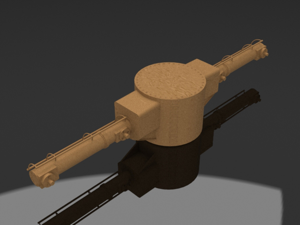
By the way, I think using wood texture on stuff like this is just plain silly.
Forgot to mention, when working with the hull surfaces, try zebra stripes, they really let you know when something is hinky.
The next thing you will want to do after you get the bow and stern added is the main deck surface. Some things to keep in mind when doing the main deck surface. It is cambered, e.g. rounded. This sheds water and adds torsional integrity to the hull. The radius is usually consistent on US ships (Bismarck and other European ships might have had a variable radius). The easiest way to do the deck surface is to use a surface sweep from the stern forward to the bow. The profile will be a very large radius arc symmetrical with the centerline. The path will start with a straight horizontal line then will go into a tangential spline somewhere near the first turret/breakwater. I would use an arc here too but the radius is always too large, SW has a radius limit of 1000 metres for all circle based geometry but the spline works too. Something you will see because of this is that the outer edge of the deck will be lower as it gets wider when everything is trimmed up.
By the way, I think using wood texture on stuff like this is just plain silly.
Forgot to mention, when working with the hull surfaces, try zebra stripes, they really let you know when something is hinky.
-
proflooney
- Posts: 213
- Joined: Fri Nov 12, 2010 3:19 pm
- Location: Moline Illinois
- Contact:
Re: Looking for Bismark Solidworks or Delftship Hull
thanks rob I have a constrained station right in the middle of the bulge but it still pops out. I have a found out in the past it usually means
A: I have an out of whack shape at that point (not the case here)
B: theres a transition shape that isnt correct ( the way I am leaning thats why I just ordered the drawings from floating drydock and through some email convos found out his drawings use original table of offsets and fixed what errors he found. so I think it will fix the problem when the proper stations arrive.
I been reading some more on the book and so while waiting for more accurate drawings started metting some with the superstructure and doing some of the surfacing tutorials.
maybe sometime later on after I do more studying and get my stations in and stuff if I have a major problem maybe you can join me on http://join.me where you can see my screen and prob see the errors better
Joe
-
rtwpsom2
- Posts: 1438
- Joined: Tue Aug 19, 2008 10:15 pm
- Location: State of Denial
Re: Looking for Bismark Solidworks or Delftship Hull
I set up an account there, but apparently it's only good for 15 days. It might be better to do a remote access, but we can worry about that later.
-
proflooney
- Posts: 213
- Joined: Fri Nov 12, 2010 3:19 pm
- Location: Moline Illinois
- Contact:
Re: Looking for Bismark Solidworks or Delftship Hull
theres no account to set up its free you just goto the page and click on the join or share. dunno what ya mean abt account as theres no account to set up
Joe
Joe