1:160 S.M.S. WESPE Armoured Gunboat (1876)
Moderators: MartinJQuinn, JIM BAUMANN, HMAS, Tiny69, Dave Wooley
-
EJFoeth
- Posts: 2919
- Joined: Wed Jan 21, 2009 1:51 pm
Re: 1:160 S.M.S. WESPE Armoured Gunboat (1876)
Oh nice, 0.2mm lathe work  Usually below the limit where my parts are already airborne!
-
DrPR

- Posts: 1689
- Joined: Sun Mar 07, 2010 12:01 am
- Location: Corvallis, Oregon, USA
- Contact:
Re: 1:160 S.M.S. WESPE Armoured Gunboat (1876)
Nice work. I know you enjoy working on the lathe and milling machine, but making a large number of pieces like this will be a tedious process!
I have shaped custom lathe cutting tools with compound curves to turn the same shape multiple times. That would reduce the time filing.
Perhaps first turning the 0.2 mm pin part at the end of the rod and then the handle closer to the chuck/collet would have fewer problems with premature separation from the rod?
Another thought is to create a rolling tool, something like a knurling tool, that could be used with soft brass rod to form the pins.
Phil
A collision at sea will ruin your entire day. Aristotle
-
wefalck

- Posts: 2112
- Joined: Wed Sep 28, 2011 12:04 pm
- Location: Paris
- Contact:
Re: 1:160 S.M.S. WESPE Armoured Gunboat (1876)
It sounds indeed logic to begin with the step-wise turning at the thinnest end, the shaft. This, however, would leave you with rounding the head of handle in a different set-up. While this is quite feasible for diameters above say 0.4 mm (and I have done it), it is very likely that the handle would just shear off when you try to do this with shaft of 0.2 mm diameter - and I do actually have one of the rare 0.2 mm collets.
So shaping the handle first was a much surer procedure and slipping with the files was inconsequential, while in the other case one may have just snapped off the part.
Also, plunging into the material at 0.2 mm cutting width seems to have excerted less forces onto the part than taking side cuts towards the collet.
I considered grinding a form-tool for the handle, but found that it would be more work than shaping the handle of the half dozen pins with files. Also, form-tools have a long cutting-edge and, therefore, excert a lot of force on the part. Although I have a (home-made) QCTP on my lathe, I prefer to cut such tiny pieces with one tool set-up due to the tolerances, when changing tools. The QCTP is quite precise, but not better than 0.05 mm.
Eberhard
Former chairman Arbeitskreis historischer Schiffbau e.V. (German Association for Shipbuilding History)
--------------------------------------------------------------------------------------------------------------------------------------------------------------------------------------------


Former chairman Arbeitskreis historischer Schiffbau e.V. (German Association for Shipbuilding History)
--------------------------------------------------------------------------------------------------------------------------------------------------------------------------------------------
-
wefalck
- Posts: 2112
- Joined: Wed Sep 28, 2011 12:04 pm
- Location: Paris
- Contact:
Re: 1:160 S.M.S. WESPE Armoured Gunboat (1876)
Interlude: Serving machine
On this model there is very limited rigging, four simple shrouds to the mast and the funnel stays. For the latter I have not come to the final conclusion, whether they may have been chain or wire. In any case there would be no serving on them, except perhaps the eyes, in case they were wire.
The mast shrouds almost certainly were wire in 1876 on a ship like this. Judging by the available photograph, they were put over the mast with eyes, which is why the mast was prepared as discussed in the previous post. Where wire shrouds go over the mast, they would be served to prevent chafing and cutting-in. As the mast does not carry any sail, the shrouds do not need to be very heavy, 16 mm diameter, i.e., 0.1 mm on the model would be sufficient, as they are also only around 16 m long. The plan is to fashion them from six strands of 0.007 mm silver wire (as apparently used to repair mobile phones and therefore readily available on ebay et al.). They would be made in pairs, looping over the mast from opposite sides and with a seizing to form the eye. The serving required would be about 10 mm long.
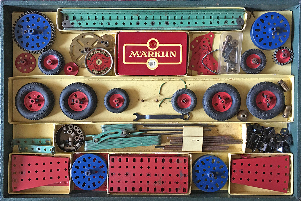
Medium-sized M�rklin construction set of ca. 1960
Given this small amount of serving needed, plus perhaps a couple of block strops, I thought I would get away for the time being with a makeshift serving machine. I kept my childhood M�rklin construction set (the German equivalent of Meccano) for such �emergencies� and proceeded to knock up a serving machine with it.
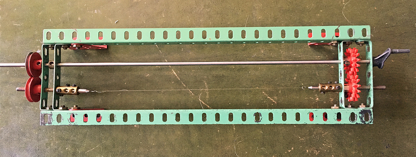
Makeshift serving machine made from M�rklin parts
Unfortunately, it turned out that I only two gears of the same size, while for a serving machine one needs two pairs with the same module and tooth count, so that they have the same distance of the shafts. I had to use two V-grooved wheels with a crossed rubber belt instead.
I first twisted the six strands of wire together to form the wire �rope� by uncoupling the drive on the left and then started to wind a 0.007 mm wire around it. While the machine worked in principle, due to the improvised drive-train on the right and the absence of proper shaft bearings, it turned only in jerks and did not run smoothly.
While it was a prove of concept, that one can actually serve a 0.1 mm wire rope with say 0.007 m wire (the thinnest I can get), it requires a precision machine to handle the very delicate material.
I had planned to postpone the construction of a proper serving machine until S.M.S. WESPE is finally completed, but will have to look into it now. The ideas are there, but I have to order the necessary materials first.
To be continued ....
On this model there is very limited rigging, four simple shrouds to the mast and the funnel stays. For the latter I have not come to the final conclusion, whether they may have been chain or wire. In any case there would be no serving on them, except perhaps the eyes, in case they were wire.
The mast shrouds almost certainly were wire in 1876 on a ship like this. Judging by the available photograph, they were put over the mast with eyes, which is why the mast was prepared as discussed in the previous post. Where wire shrouds go over the mast, they would be served to prevent chafing and cutting-in. As the mast does not carry any sail, the shrouds do not need to be very heavy, 16 mm diameter, i.e., 0.1 mm on the model would be sufficient, as they are also only around 16 m long. The plan is to fashion them from six strands of 0.007 mm silver wire (as apparently used to repair mobile phones and therefore readily available on ebay et al.). They would be made in pairs, looping over the mast from opposite sides and with a seizing to form the eye. The serving required would be about 10 mm long.
Medium-sized M�rklin construction set of ca. 1960
Given this small amount of serving needed, plus perhaps a couple of block strops, I thought I would get away for the time being with a makeshift serving machine. I kept my childhood M�rklin construction set (the German equivalent of Meccano) for such �emergencies� and proceeded to knock up a serving machine with it.
Makeshift serving machine made from M�rklin parts
Unfortunately, it turned out that I only two gears of the same size, while for a serving machine one needs two pairs with the same module and tooth count, so that they have the same distance of the shafts. I had to use two V-grooved wheels with a crossed rubber belt instead.
I first twisted the six strands of wire together to form the wire �rope� by uncoupling the drive on the left and then started to wind a 0.007 mm wire around it. While the machine worked in principle, due to the improvised drive-train on the right and the absence of proper shaft bearings, it turned only in jerks and did not run smoothly.
While it was a prove of concept, that one can actually serve a 0.1 mm wire rope with say 0.007 m wire (the thinnest I can get), it requires a precision machine to handle the very delicate material.
I had planned to postpone the construction of a proper serving machine until S.M.S. WESPE is finally completed, but will have to look into it now. The ideas are there, but I have to order the necessary materials first.
To be continued ....
Eberhard
Former chairman Arbeitskreis historischer Schiffbau e.V. (German Association for Shipbuilding History)
--------------------------------------------------------------------------------------------------------------------------------------------------------------------------------------------
Former chairman Arbeitskreis historischer Schiffbau e.V. (German Association for Shipbuilding History)
--------------------------------------------------------------------------------------------------------------------------------------------------------------------------------------------
-
DrPR
- Posts: 1689
- Joined: Sun Mar 07, 2010 12:01 am
- Location: Corvallis, Oregon, USA
- Contact:
Re: 1:160 S.M.S. WESPE Armoured Gunboat (1876)
I found small diameter bead stringing wire at a local craft store. It is mostly 7 strand, stainless steel with a nylon coating, and the smallest diameter I have is 0.30 mm (0.012 inch).
I don't know the smallest diameter that is made, but you might search through jewelry supplies.
Phil
I don't know the smallest diameter that is made, but you might search through jewelry supplies.
Phil
A collision at sea will ruin your entire day. Aristotle
-
wefalck
- Posts: 2112
- Joined: Wed Sep 28, 2011 12:04 pm
- Location: Paris
- Contact:
Re: 1:160 S.M.S. WESPE Armoured Gunboat (1876)
As I said, the thinnest wire in my stock is 0.007 mm (= 0.000028") silver wire - this is about half the diamter of the very thinnest human hair and barely visible with the naked eye. Apparently these wires are used to repair broken links on PCBs in mobile phones and the likes. I also have 0.02 mm copper wire ...
Thanks to ebay et al. such speciality wires are now easily accessible. Previously they were only available from speciality suppliers and you had to be lucky to have a shop nearby, if they were sold in shops or to non-professional customers at all.
Thanks to ebay et al. such speciality wires are now easily accessible. Previously they were only available from speciality suppliers and you had to be lucky to have a shop nearby, if they were sold in shops or to non-professional customers at all.
Eberhard
Former chairman Arbeitskreis historischer Schiffbau e.V. (German Association for Shipbuilding History)
--------------------------------------------------------------------------------------------------------------------------------------------------------------------------------------------
Former chairman Arbeitskreis historischer Schiffbau e.V. (German Association for Shipbuilding History)
--------------------------------------------------------------------------------------------------------------------------------------------------------------------------------------------
-
Iceman 29

- Posts: 1945
- Joined: Tue Sep 29, 2020 4:35 pm
- Location: Bretagne, France
Re: 1:160 S.M.S. WESPE Armoured Gunboat (1876)
Good question!marijn van gils wrote:Now THAT is fine work!
Did you turn the mast on the lathe too, or in a drill (maybe finishing the base and the shoulder in the lathe?)?
Excellent jobs.
Pascal
�Battleship Bretagne 3D: https://vu.fr/FvCY
�SS Delphine 3D: https://vu.fr/NeuO
�SS Nomadic 3D: https://vu.fr/tAyL
�USS Nokomis 3D: https://vu.fr/kntC
�USS Pamanset 3D: https://vu.fr/jXGQ
�Battleship Bretagne 3D: https://vu.fr/FvCY
�SS Delphine 3D: https://vu.fr/NeuO
�SS Nomadic 3D: https://vu.fr/tAyL
�USS Nokomis 3D: https://vu.fr/kntC
�USS Pamanset 3D: https://vu.fr/jXGQ
-
wefalck
- Posts: 2112
- Joined: Wed Sep 28, 2011 12:04 pm
- Location: Paris
- Contact:
Re: 1:160 S.M.S. WESPE Armoured Gunboat (1876)
Sorry Maijn, I missed your question ...
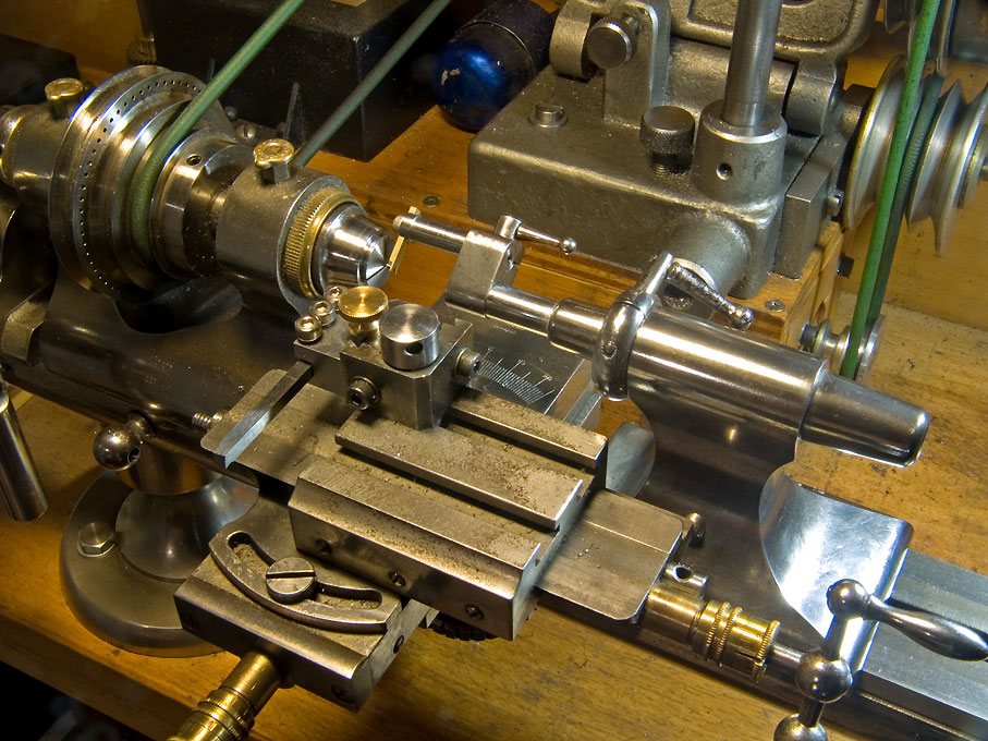
Over the years I made all sorts of fancy attachments for the watchmaking lathe that allow me to work on long, thin parts, including the two types of fixed steadies below:

See also: https://www.maritima-et-mechanika.org/t ... ure_steady
The problem with watchmaking lathes is that the longitudinal and cross-slide are interchanged compared to an engineer's lathe, i.e. the longitudinal slides sits on top of the cross-slide. This means that is not so easy to have a travelling steady, which is really what one should have here.
The mast was turned in steps and the longitudinal slide off-set by a fraction of a degree to produce the taper (by trial and error). The end of the material was supported by a tailstock centre. After turning the 'top-mast' above the shoulder, the stock was moved out of the collet and supported by the first steady above for turning the taper on the 'lower mast'.
I also use the flexing of pieces under the turning load to produce the curved shape spars normally have. It is a question of trial and error and one may need to support the part on a strategic point to reduce the flexing. It's a bit of an art, rather than proper 'engineering' at this point.
Over the years I made all sorts of fancy attachments for the watchmaking lathe that allow me to work on long, thin parts, including the two types of fixed steadies below:
See also: https://www.maritima-et-mechanika.org/t ... ure_steady
The problem with watchmaking lathes is that the longitudinal and cross-slide are interchanged compared to an engineer's lathe, i.e. the longitudinal slides sits on top of the cross-slide. This means that is not so easy to have a travelling steady, which is really what one should have here.
The mast was turned in steps and the longitudinal slide off-set by a fraction of a degree to produce the taper (by trial and error). The end of the material was supported by a tailstock centre. After turning the 'top-mast' above the shoulder, the stock was moved out of the collet and supported by the first steady above for turning the taper on the 'lower mast'.
I also use the flexing of pieces under the turning load to produce the curved shape spars normally have. It is a question of trial and error and one may need to support the part on a strategic point to reduce the flexing. It's a bit of an art, rather than proper 'engineering' at this point.
Eberhard
Former chairman Arbeitskreis historischer Schiffbau e.V. (German Association for Shipbuilding History)
--------------------------------------------------------------------------------------------------------------------------------------------------------------------------------------------
Former chairman Arbeitskreis historischer Schiffbau e.V. (German Association for Shipbuilding History)
--------------------------------------------------------------------------------------------------------------------------------------------------------------------------------------------
-
JIM BAUMANN

- Posts: 5687
- Joined: Mon Jan 10, 2005 5:30 pm
- Location: Nr Southampton England
Re: 1:160 S.M.S. WESPE Armoured Gunboat (1876)
You and your most fancy lathe works....
most impressive, but sadly my comprehension thereof blanks somewhat at times-
-much the way it does when a IT geek tries to explain the inner workings of my PC....
in good German
Ich versteh nur Bahnhof
( for non-german speakers....
" I understand only Railways station"
more amusing in German alas....
....I buy them at three times the speed I build 'em.... will I live long enough to empty my stash...?
http://www.modelshipgallery.com/gallery ... index.html
IPMS UK SIG (special interest group) www.finewaterline.com
http://www.modelshipgallery.com/gallery ... index.html
IPMS UK SIG (special interest group) www.finewaterline.com
-
wefalck
- Posts: 2112
- Joined: Wed Sep 28, 2011 12:04 pm
- Location: Paris
- Contact:
Re: 1:160 S.M.S. WESPE Armoured Gunboat (1876)
What can I do against you only understanding 'Bahnhof', Jim ... ?
*****************************************************************
Funnel and Boiler-Room Ventilators
Not really much to write about, as the parts had been built quite a while ago. Just a bit of assembly work and painting. Unfortunately, I forgot to take a picture of the assembled parts before painting. Just before painting, also the turning handles for the ventilators were glued on using shellac. These are made from 0.1 mm wire flattened at the ends using a specially made die in my little jewelling press. They are extremely delicate.
The colour of the funnel and the boiler-ventilators may be debatable. Research on possible colours arrived at nothing. The 1874 ordinance states that funnels should be �yellow� or �mast-colour�, but I could not establish what this yellow actually looked like. A colleague recently discovered an 1890 ordinance that specified that the �mast-colour� should be mixed from 460 g dry white-lead and 260 g dry light ochre pigment with 300 g varnish, to be diluted for application with a further 310 g of varnish. The ratio between white-lead and light ochre suggests a rather light yellow hue, but we do not have a real clue to its actual hue. Circumstantial evidence, such as paintings, seems to suggest that in those early years of the Imperial Navy the yellow was indeed lighter than in later years. Preserved models from the later 1880s show a darker and murkier yellow than one might expect from the above recipe, while the strong yellow of the late tropical livery of the Imperial Navy had a decidedly orange tint. The buff/yellow of the RN seems to have undergone a similar development, while the French navy used a rather murky beige.
The first photograph of S.M.S. WESPE of 1876 must have been taken either on a wet collodium or on a dry gelatine plate. Both of which have little red sensitiveness and, therefore, represent colours at the �warm� end of the visible spectrum darker than one would expect from a panochromatic film. The funnel thus appears considerably darker than the white of superstructure. After some colour testing, I finally decided on Vallejo Model Air 71.107 �US interior yellow�.
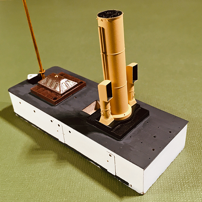
Bow view of the assembly of funnel and boiler-room ventilators
The boiler-room ventilators show the same level of grey as the funnel and are decidedly darker than the other ventilators. This indicates that they were also painted yellow, while the 1874 ordinance prescribed white for ventilators. Given their closeness to the funnel it does make aesthetic sense to have them painted yellow.
Another issue is the interior colour of the ventilators. We seem to take it for granted that ventilators are red inside mostly, but it is not clear when and how this fashion came about. Perhaps they were painted red to resemble the copper that was frequently used in their manufacture in earlier years? On the early photograph the interiors appear very dark, but due to the limited red-sensitivity this is not conclusive evidence that they may have been painted black. Nevertheless, in the end I decided on black for the interior of all ventilators.
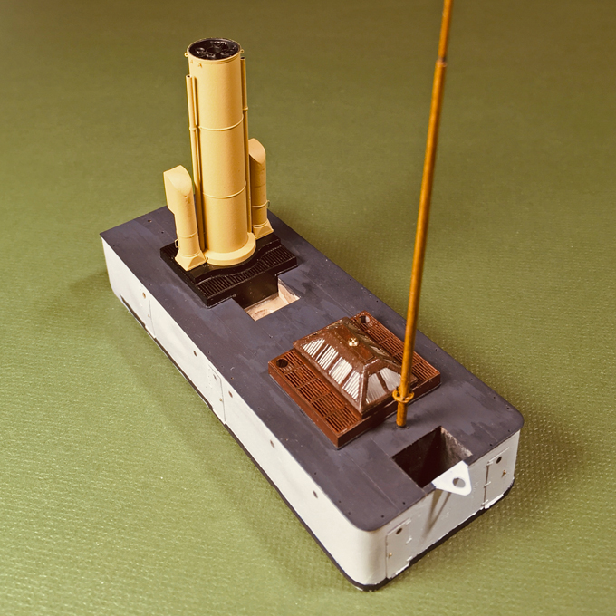
Stern view of the assembly of funnel and boiler-room ventilators
To be continued ....
*****************************************************************
Funnel and Boiler-Room Ventilators
Not really much to write about, as the parts had been built quite a while ago. Just a bit of assembly work and painting. Unfortunately, I forgot to take a picture of the assembled parts before painting. Just before painting, also the turning handles for the ventilators were glued on using shellac. These are made from 0.1 mm wire flattened at the ends using a specially made die in my little jewelling press. They are extremely delicate.
The colour of the funnel and the boiler-ventilators may be debatable. Research on possible colours arrived at nothing. The 1874 ordinance states that funnels should be �yellow� or �mast-colour�, but I could not establish what this yellow actually looked like. A colleague recently discovered an 1890 ordinance that specified that the �mast-colour� should be mixed from 460 g dry white-lead and 260 g dry light ochre pigment with 300 g varnish, to be diluted for application with a further 310 g of varnish. The ratio between white-lead and light ochre suggests a rather light yellow hue, but we do not have a real clue to its actual hue. Circumstantial evidence, such as paintings, seems to suggest that in those early years of the Imperial Navy the yellow was indeed lighter than in later years. Preserved models from the later 1880s show a darker and murkier yellow than one might expect from the above recipe, while the strong yellow of the late tropical livery of the Imperial Navy had a decidedly orange tint. The buff/yellow of the RN seems to have undergone a similar development, while the French navy used a rather murky beige.
The first photograph of S.M.S. WESPE of 1876 must have been taken either on a wet collodium or on a dry gelatine plate. Both of which have little red sensitiveness and, therefore, represent colours at the �warm� end of the visible spectrum darker than one would expect from a panochromatic film. The funnel thus appears considerably darker than the white of superstructure. After some colour testing, I finally decided on Vallejo Model Air 71.107 �US interior yellow�.
Bow view of the assembly of funnel and boiler-room ventilators
The boiler-room ventilators show the same level of grey as the funnel and are decidedly darker than the other ventilators. This indicates that they were also painted yellow, while the 1874 ordinance prescribed white for ventilators. Given their closeness to the funnel it does make aesthetic sense to have them painted yellow.
Another issue is the interior colour of the ventilators. We seem to take it for granted that ventilators are red inside mostly, but it is not clear when and how this fashion came about. Perhaps they were painted red to resemble the copper that was frequently used in their manufacture in earlier years? On the early photograph the interiors appear very dark, but due to the limited red-sensitivity this is not conclusive evidence that they may have been painted black. Nevertheless, in the end I decided on black for the interior of all ventilators.
Stern view of the assembly of funnel and boiler-room ventilators
To be continued ....
Eberhard
Former chairman Arbeitskreis historischer Schiffbau e.V. (German Association for Shipbuilding History)
--------------------------------------------------------------------------------------------------------------------------------------------------------------------------------------------
Former chairman Arbeitskreis historischer Schiffbau e.V. (German Association for Shipbuilding History)
--------------------------------------------------------------------------------------------------------------------------------------------------------------------------------------------
-
marijn van gils
- Posts: 2697
- Joined: Tue Feb 06, 2007 10:24 am
- Location: Belgium
Re: 1:160 S.M.S. WESPE Armoured Gunboat (1876)
Beautiful work!
Thanks for all the information. Those steady rests look great!
I bought the Proxxon steady rest for my lathe, which is useful for other things but indeed not suitable for turning anything as long and thin as spars because they flex too much. And to my frustration, Proxxon doesn't make a travelling rest that fits my lathe. Luckily there is still the 'turning-in-a-handheld-motortool' method for spars, which is of course less precise but sufficient for our needs.
It really is not as complicated as it looks. I have had no technical schooling whatsoever (literary zero!), but only an hour of a modelling friend explaining the basics and showing them hands-on was enough to get me started, and after a week I was turning 1/300 gun barrels.
Eberhard's machine and accessories look daunting to the beginner, but while they are fantastic they are not necessary for most stuff. One simple machine will do a lot.
So, if you have a friend who can show you the basics and let you 'play' on his machine a little, take the opportunity I would say!
I understand the IT-analogy, but there is one big difference: turning is much less abstract; it is still a very physical activity, and really a lot of fun (I don't find pleasure in computer stuff either...)
There are some great youtube video's on the subject. Even if you're not going to be doing it yourself, these can be pretty relaxing to watch.
I liked the ones of this channel a lot:
https://www.youtube.com/c/Blondihacks/playlists
Check out the 'lathe skills' playlist.
That doesn't need to be problem!wefalck wrote:It's a bit of an art, rather than proper 'engineering' at this point.
Thanks for all the information. Those steady rests look great!
I bought the Proxxon steady rest for my lathe, which is useful for other things but indeed not suitable for turning anything as long and thin as spars because they flex too much. And to my frustration, Proxxon doesn't make a travelling rest that fits my lathe. Luckily there is still the 'turning-in-a-handheld-motortool' method for spars, which is of course less precise but sufficient for our needs.
Very understandable Jim (I was the same not too long ago), but I would like to offer a word of encouragement:JIM BAUMANN wrote:most impressive, but sadly my comprehension thereof blanks somewhat at times-
-much the way it does when a IT geek tries to explain the inner workings of my PC....
It really is not as complicated as it looks. I have had no technical schooling whatsoever (literary zero!), but only an hour of a modelling friend explaining the basics and showing them hands-on was enough to get me started, and after a week I was turning 1/300 gun barrels.
Eberhard's machine and accessories look daunting to the beginner, but while they are fantastic they are not necessary for most stuff. One simple machine will do a lot.
So, if you have a friend who can show you the basics and let you 'play' on his machine a little, take the opportunity I would say!
I understand the IT-analogy, but there is one big difference: turning is much less abstract; it is still a very physical activity, and really a lot of fun (I don't find pleasure in computer stuff either...)
There are some great youtube video's on the subject. Even if you're not going to be doing it yourself, these can be pretty relaxing to watch.
I liked the ones of this channel a lot:
https://www.youtube.com/c/Blondihacks/playlists
Check out the 'lathe skills' playlist.
-
wefalck
- Posts: 2112
- Joined: Wed Sep 28, 2011 12:04 pm
- Location: Paris
- Contact:
Re: 1:160 S.M.S. WESPE Armoured Gunboat (1876)
Indeed, that lady does a lot of good things and her practical advice is sound. I am following her channel on YouTube.
I was lucky, that my university at the time (ETH Z�rich) had a large workshop equipped with surplus (while outdated for them) machine tools donated by various big industrial companies in the region (who took on most of the new enginnering graduates). The workshop was run by and old grumpy mechanic, but somehow I got on with him very well (in spite of being from the big Kanton in the North) and he tought me some basic machining skills. All the rest is self-taught after I got my first lathe and a lot of reading - old pre WW2 machinist's textbooks are the most useful for this.
These old machine tools became a hobby of its own, their collection and refurbishment.
Eberhard
Former chairman Arbeitskreis historischer Schiffbau e.V. (German Association for Shipbuilding History)
--------------------------------------------------------------------------------------------------------------------------------------------------------------------------------------------
Former chairman Arbeitskreis historischer Schiffbau e.V. (German Association for Shipbuilding History)
--------------------------------------------------------------------------------------------------------------------------------------------------------------------------------------------
-
wefalck
- Posts: 2112
- Joined: Wed Sep 28, 2011 12:04 pm
- Location: Paris
- Contact:
Re: 1:160 S.M.S. WESPE Armoured Gunboat (1876)
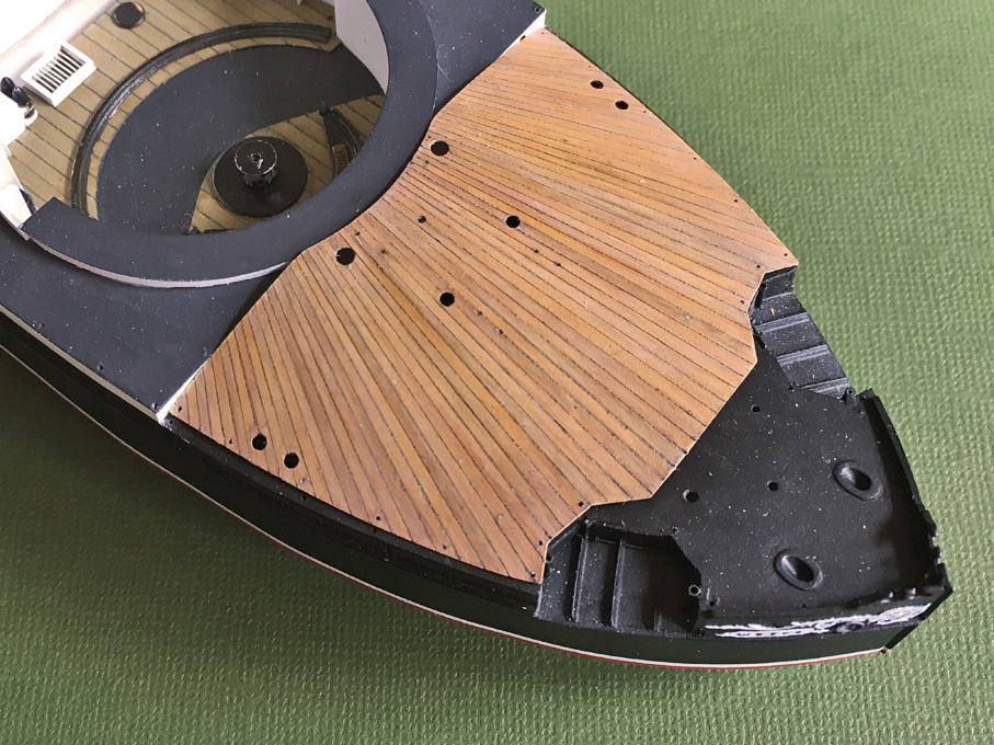
Quarter-deck v4
While the wooden quarter-deck previously produced (v2) was not entirely bad, it lacked the crispiness I had wished for and also the colour was somewhat murky, more like oak, and not like the teak it was probably made from. In addition, I found a mistake in its shape that could not be corrected.
This quarter-deck is somewhat unusual in lay-out, as the planks are radiating with the gun-pivot as centre. This lay-out probably was chosen to minimise the effect of the certainly considerable blast from the 30.5 cm-gun. Apart from the fact that most wood-species would be too coarse at 1:160 scale, it would also be a challenge to produce such deck with tapering planks only 0.4 mm thick. A painted version renders more likely a realistic representation, is technically easier to achieve and more in line with the style of the model.
The shape of the wooden deck was cut from a 0.4 mm thick sheet of bakelite-paper and carefully fitted to the hull of the model, which was quite a bit of work given the multiple curvatures. The caulked seams were indicated by narrow engraved lines as described earlier in this building log. The holes for all the fittings were also drilled at this stage.
In between, I had tried using black styrene, rather than bakelite-paper as a basis for the decking (v3). The rationale was that I would clear out the engraved lines after painting down to the black plastic. This strategy did not work for two reasons, namely the styrene (Evergreen� sheet) is much softer than the bakelite and the acrylic paints form a kind of quite soft skin, which tends to rip in flakes when trying to re-engrave the lines, so that I dropped this idea.
The wood character of the quarter-decking was to be achieved by giving each plank a slightly different colour, imitating the natural variability of wood. The piece was given a base-coat of Vallejo Model Air 71075 �sand (ivory)� using the airbrush. In a next step single planks were randomly given a light wash with Prince August 834 �natural wood transparent� or Vallejo Model Air 71023 �hemp� (which turned out to be a bit too dark actually). In a next step randomly selected planks, particularly those �hemp� ones were given a very light wash with Vallejo Model Air 71288 �Portland stone�. Another very light wash with Vallejo Model Air 71041 �armour brown�, toned down with yet another very light wash using Vallejo Model Air 71132 �aged white�, pulled everything together.
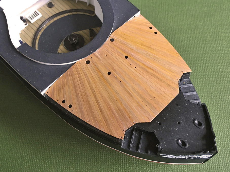
Painted quarter-decking before sealing it with varnish
To facilitate the picking out of the caulking seams, the decking was given a sealing coat of acrylic glossy varnish. The definition of the caulking seams was enhanced by running the back of an old scalpel along them, making impressions, rather than cutting through the paint. The caulking was imitated using a 0.05 mm marker with pigmented permanent (hopefully) ink. After each line was drawn, the ink was allowed to dry for a few seconds and the excess wiped off with a barely humid finger. This leaves the ink only in the incisions, resulting in a very thin black line. In spite of the glossy varnish, a haze of the ink is left on the planks, darkening them somewhat, but this effect was calculated in, when setting out the original paint scheme.
The surface was lightly rubbed down with an abrasive foam block (as used in mani-/pedicure) to thin down the glossy varnish without damaging the underlying paint. This rather complex procedure was concluded by applying another very dilute wash of Vallejo Model Air 71132 �aged white� and finally a sprayed on coating of Vallejo matt varnish.
Finished quarter-decking ready for final installation
To be continued ....
While the wooden quarter-deck previously produced (v2) was not entirely bad, it lacked the crispiness I had wished for and also the colour was somewhat murky, more like oak, and not like the teak it was probably made from. In addition, I found a mistake in its shape that could not be corrected.
This quarter-deck is somewhat unusual in lay-out, as the planks are radiating with the gun-pivot as centre. This lay-out probably was chosen to minimise the effect of the certainly considerable blast from the 30.5 cm-gun. Apart from the fact that most wood-species would be too coarse at 1:160 scale, it would also be a challenge to produce such deck with tapering planks only 0.4 mm thick. A painted version renders more likely a realistic representation, is technically easier to achieve and more in line with the style of the model.
The shape of the wooden deck was cut from a 0.4 mm thick sheet of bakelite-paper and carefully fitted to the hull of the model, which was quite a bit of work given the multiple curvatures. The caulked seams were indicated by narrow engraved lines as described earlier in this building log. The holes for all the fittings were also drilled at this stage.
In between, I had tried using black styrene, rather than bakelite-paper as a basis for the decking (v3). The rationale was that I would clear out the engraved lines after painting down to the black plastic. This strategy did not work for two reasons, namely the styrene (Evergreen� sheet) is much softer than the bakelite and the acrylic paints form a kind of quite soft skin, which tends to rip in flakes when trying to re-engrave the lines, so that I dropped this idea.
The wood character of the quarter-decking was to be achieved by giving each plank a slightly different colour, imitating the natural variability of wood. The piece was given a base-coat of Vallejo Model Air 71075 �sand (ivory)� using the airbrush. In a next step single planks were randomly given a light wash with Prince August 834 �natural wood transparent� or Vallejo Model Air 71023 �hemp� (which turned out to be a bit too dark actually). In a next step randomly selected planks, particularly those �hemp� ones were given a very light wash with Vallejo Model Air 71288 �Portland stone�. Another very light wash with Vallejo Model Air 71041 �armour brown�, toned down with yet another very light wash using Vallejo Model Air 71132 �aged white�, pulled everything together.
Painted quarter-decking before sealing it with varnish
To facilitate the picking out of the caulking seams, the decking was given a sealing coat of acrylic glossy varnish. The definition of the caulking seams was enhanced by running the back of an old scalpel along them, making impressions, rather than cutting through the paint. The caulking was imitated using a 0.05 mm marker with pigmented permanent (hopefully) ink. After each line was drawn, the ink was allowed to dry for a few seconds and the excess wiped off with a barely humid finger. This leaves the ink only in the incisions, resulting in a very thin black line. In spite of the glossy varnish, a haze of the ink is left on the planks, darkening them somewhat, but this effect was calculated in, when setting out the original paint scheme.
The surface was lightly rubbed down with an abrasive foam block (as used in mani-/pedicure) to thin down the glossy varnish without damaging the underlying paint. This rather complex procedure was concluded by applying another very dilute wash of Vallejo Model Air 71132 �aged white� and finally a sprayed on coating of Vallejo matt varnish.
Finished quarter-decking ready for final installation
To be continued ....
Eberhard
Former chairman Arbeitskreis historischer Schiffbau e.V. (German Association for Shipbuilding History)
--------------------------------------------------------------------------------------------------------------------------------------------------------------------------------------------
Former chairman Arbeitskreis historischer Schiffbau e.V. (German Association for Shipbuilding History)
--------------------------------------------------------------------------------------------------------------------------------------------------------------------------------------------
-
Iceman 29
- Posts: 1945
- Joined: Tue Sep 29, 2020 4:35 pm
- Location: Bretagne, France
Re: 1:160 S.M.S. WESPE Armoured Gunboat (1876)
Your efforts have paid off, it is very successful and especially very realistic. 
Pascal
�Battleship Bretagne 3D: https://vu.fr/FvCY
�SS Delphine 3D: https://vu.fr/NeuO
�SS Nomadic 3D: https://vu.fr/tAyL
�USS Nokomis 3D: https://vu.fr/kntC
�USS Pamanset 3D: https://vu.fr/jXGQ
�Battleship Bretagne 3D: https://vu.fr/FvCY
�SS Delphine 3D: https://vu.fr/NeuO
�SS Nomadic 3D: https://vu.fr/tAyL
�USS Nokomis 3D: https://vu.fr/kntC
�USS Pamanset 3D: https://vu.fr/jXGQ
-
Fliger747
- Posts: 5068
- Joined: Wed Jan 02, 2013 1:15 am
Re: 1:160 S.M.S. WESPE Armoured Gunboat (1876)
Indeed! In is never a mistake in the progress of a model to upgrade the construction, I have always been happy to have done this!
Best regards! Tom
Best regards! Tom
-
wefalck
- Posts: 2112
- Joined: Wed Sep 28, 2011 12:04 pm
- Location: Paris
- Contact:
Re: 1:160 S.M.S. WESPE Armoured Gunboat (1876)
Thanks again, gentlemen, for your continued moral support!
**************************************************************
Quarter-deck � further work
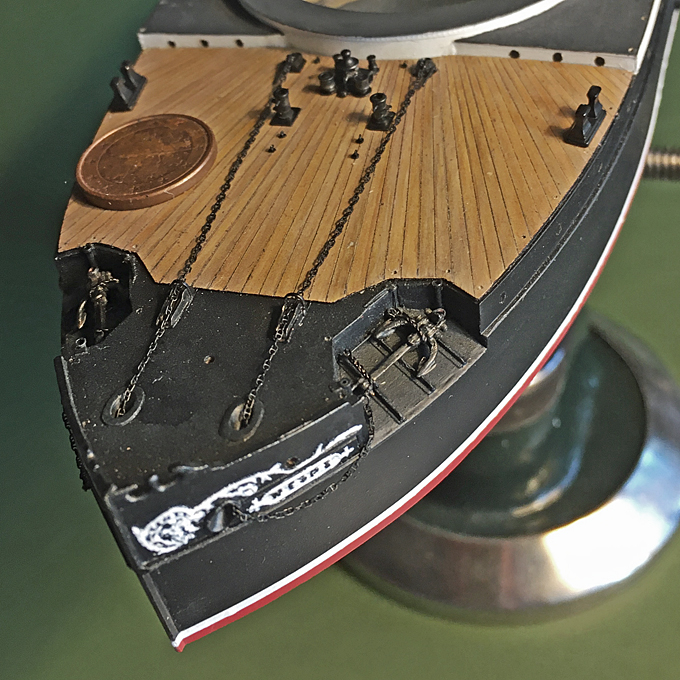
Having now satisfactory wooden decking for the quarter-deck, this was permanently cemented into place, allowing to progress with the installation of the various bits and pieces that had been fabricated years ago. These include the anchor capstan, the four patent chain-stoppers, chain-bollards (which are hollow and double as a base for the crew accommodation ventilators), various eye-bolts to which stoppers are shackled, that secure the chains during mooring, and the forward pair of mooring bollards.
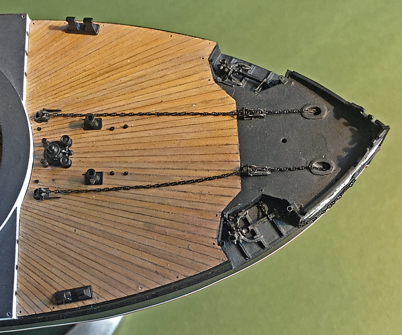
Populated quarter-deck
Probably the only bought-in item will the studded anchor-chain. Recently, some really good 3D-printed chains have become available. My excuse is that that many shipyards did not make the chains themselves either, but bought them from specialised forgeries (apart from the fact that I didn�t want to go insane over making such microscopic studded chains). I choose the smallest size from yxmodels (Product no. YXN700-001). With 8� plus shipping for a length of 120 mm they are the most expensive (not considering my time) item on board. They are printed in a light brown resin and were given several light dusts with acrylic paint to turn them black without clogging up or cementing the links together. The connecting link with the anchor shackle was bent from 0.2 mm tinned copper wire.
The anchors are held in place with chains attached to the release gear that had already been installed. These chains were imitated by twisting together two strands of 0.1 mm blackened copper wire so that each twist is about the length of the assumed link length. The length of twisted wire then was folded over in half and twisted together in the opposite sense. With some imagination this looks quite like a slightly twisted chain. The anchor were secured in place with a couple of dots of shellack and then release chains installed � which not unexpectedly was a really fiddly task.
I arranged the chains as they would be kept ready for dropping the anchor or in light weather, without further securing by rope chain-stoppers, as I do not have any pictorial evidence for how that would have been done on the real ship.
The quarter-deck later will receive some light weathering and the chain-rails need to be installed, but as they are extremely fragile, this will be put off to the moment, when the model is installed on its final base-plate.
Populated quarter-deck
To be continued ....
**************************************************************
Quarter-deck � further work
Having now satisfactory wooden decking for the quarter-deck, this was permanently cemented into place, allowing to progress with the installation of the various bits and pieces that had been fabricated years ago. These include the anchor capstan, the four patent chain-stoppers, chain-bollards (which are hollow and double as a base for the crew accommodation ventilators), various eye-bolts to which stoppers are shackled, that secure the chains during mooring, and the forward pair of mooring bollards.
Populated quarter-deck
Probably the only bought-in item will the studded anchor-chain. Recently, some really good 3D-printed chains have become available. My excuse is that that many shipyards did not make the chains themselves either, but bought them from specialised forgeries (apart from the fact that I didn�t want to go insane over making such microscopic studded chains). I choose the smallest size from yxmodels (Product no. YXN700-001). With 8� plus shipping for a length of 120 mm they are the most expensive (not considering my time) item on board. They are printed in a light brown resin and were given several light dusts with acrylic paint to turn them black without clogging up or cementing the links together. The connecting link with the anchor shackle was bent from 0.2 mm tinned copper wire.
The anchors are held in place with chains attached to the release gear that had already been installed. These chains were imitated by twisting together two strands of 0.1 mm blackened copper wire so that each twist is about the length of the assumed link length. The length of twisted wire then was folded over in half and twisted together in the opposite sense. With some imagination this looks quite like a slightly twisted chain. The anchor were secured in place with a couple of dots of shellack and then release chains installed � which not unexpectedly was a really fiddly task.
I arranged the chains as they would be kept ready for dropping the anchor or in light weather, without further securing by rope chain-stoppers, as I do not have any pictorial evidence for how that would have been done on the real ship.
The quarter-deck later will receive some light weathering and the chain-rails need to be installed, but as they are extremely fragile, this will be put off to the moment, when the model is installed on its final base-plate.
Populated quarter-deck
To be continued ....
Eberhard
Former chairman Arbeitskreis historischer Schiffbau e.V. (German Association for Shipbuilding History)
--------------------------------------------------------------------------------------------------------------------------------------------------------------------------------------------
Former chairman Arbeitskreis historischer Schiffbau e.V. (German Association for Shipbuilding History)
--------------------------------------------------------------------------------------------------------------------------------------------------------------------------------------------
-
DrPR
- Posts: 1689
- Joined: Sun Mar 07, 2010 12:01 am
- Location: Corvallis, Oregon, USA
- Contact:
Re: 1:160 S.M.S. WESPE Armoured Gunboat (1876)
Beautiful work! Very nice craftsmanship.
Phil
Phil
A collision at sea will ruin your entire day. Aristotle
-
JIM BAUMANN
- Posts: 5687
- Joined: Mon Jan 10, 2005 5:30 pm
- Location: Nr Southampton England
Re: 1:160 S.M.S. WESPE Armoured Gunboat (1876)
Your foredeck is really a mist excellent thing to behold.
Your technique is innovative and has borne fruit of high quality
I trust you can see the light at the end of the tunnel..?
Best wishes and continued strength to complete!
JIM B
Your technique is innovative and has borne fruit of high quality
I trust you can see the light at the end of the tunnel..?
Best wishes and continued strength to complete!
JIM B
....I buy them at three times the speed I build 'em.... will I live long enough to empty my stash...?
http://www.modelshipgallery.com/gallery ... index.html
IPMS UK SIG (special interest group) www.finewaterline.com
http://www.modelshipgallery.com/gallery ... index.html
IPMS UK SIG (special interest group) www.finewaterline.com
-
wefalck
- Posts: 2112
- Joined: Wed Sep 28, 2011 12:04 pm
- Location: Paris
- Contact:
Re: 1:160 S.M.S. WESPE Armoured Gunboat (1876)
Thanks again, gentlemen !
***************************
Mounting the model
In another thread the question was raised as to when (permanently) mounting the model. It is a question of scale, of course, and also whether we are looking at a full-hull or a waterline-model. Smaller scale model can be very delicate, while larger scale models tend to be inherently more robust. A waterline-model may not offer you a lot of positions from which you can grab it during construction and final mounting. So, in general, it will have to be done earlier than for a full-hull model. In this particular case, adding more delicate items, particularly also those outside the hull, would make it almost impossible to handle the model without damaging it. Therefore, it was decided to prepare the mounting now.
The base-plate, a piece of 20 mm thick, MDF, forms an integral part of the display case that had been constructed earlier. To this the model will be fixed with a single wood-screw from the bottom. The hole in the model for this had been drilled early on in the construction process. I did not envisage to have to mount and unmount the model frequently, otherwise I would have embedded a threaded nut into the bread-and-butter hull and used a machine screw instead.
With hindsight, I perhaps should have extended the hull a bit more than just 2 mm below the waterline. The 2 mm are not that much to model the sea, but would translate into a wave-height of around 32 cm or a good foot.
The scenario I imagined for the presentation is that the ship moves in a rather calm sea, but at moderate speed (the max. speed of the WESPE-class was only around 10 kn anyway). The weather is fine, with sun and a light breeze � a summer day on the North Sea or the Baltic.
There is only one image I am aware off, that shows one of the boats moving, S.M.S. NATTER moving slowly along the Kiel-Kanal. Therefore, we do not really know what their wave-pattern would have looked like. The bow is quite full, it has a ram protruding below the waterline, and hard bilges with a flat bottom. In a way, this is the form of our river freighters. Therefore, I looked around on the Internet for pictures that show such ships on the move. Of course, there is a difference in wave patterns due to the restricted water depths in river channels. The wake would be more or less a Kelvin pattern with the waves radiating from the ship with an included angle of around 40�. The base is not much bigger than the ship to allow close-up view of the model, so there is actually not so much sea to model.
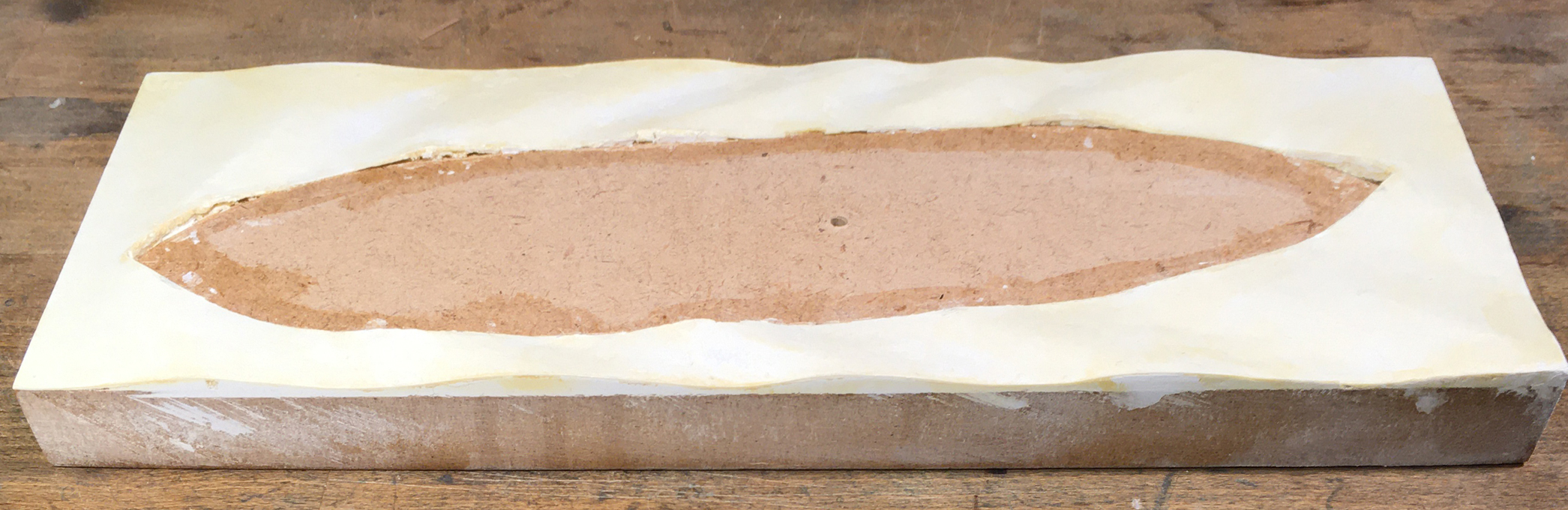
Base-board covered in moulded water-colour paper and primed
I decided to try something new (for me) and instead of sculpting and carving the sea from plaster of Paris, as I had done in the past, I used a sheet of thick water-colour paper. The waves were formed by placing thin scraps of acrylic foam (because I happen to have some) underneath and then gluing it down with white glue, working from the bow to the stern. The space for the model was cut out first, of course. Once the glue set, the paper was trimmed to size. The gaps under the paper were filled with acrylic wood-repair putty and the edges sanded smooth once the putty had set. At this stage also the fit of both, the model and the display case were checked and small corrections made. Finally, the whole base was given a coat of sanding filler to seal the paper and the wood. The edges were sanded smooth again.
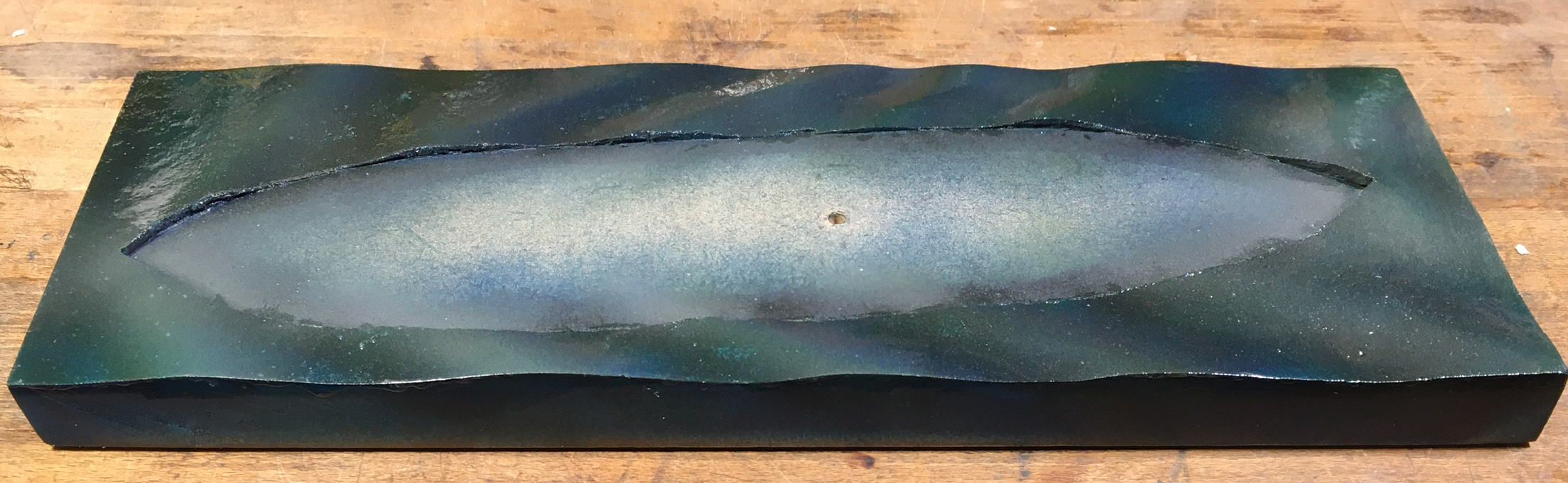
Base colouring sealed with gloss varnish
Painting proceeded in several steps. First a coat of Schmincke AeroColor turquois acrylic was applied by airbrush. However, the paint was applied in a glancing fashion against the direction of the waves. A second coat using Vallejo ModelAir �steel blue�, again glancing, but with the waves was applied. Here in this application, it is not really apparent, but when there are shorter, steeper waves modelled this causes a colour change effect, when you look at the sea-scape from different angles. The front of the waves then was lightened up somewhat by a light spray of Schmincke AeroColor chrome-oxide green and the crest areas further lightened up with a light dust of Vallejo ModelAir �hemp� to give the sea a flatter green appearance. This base colouring was sealed by two generous coats of acrylic gloss varnish applied with a flat hairbrush.
In the next step, the wave crests were modelled using acrylic gel and gel filled with acrylic �micro-balloons�. In the past I actually used crystal sugar as a filler, which works very well, as not all crystals dissolve, but remain as transparent parts. I used this even before I became aware of acrylic gels together with wallpaper-glue and this �icing� is holding up well after 40+ years. Part of the bow-wave was sculpted again in this way.
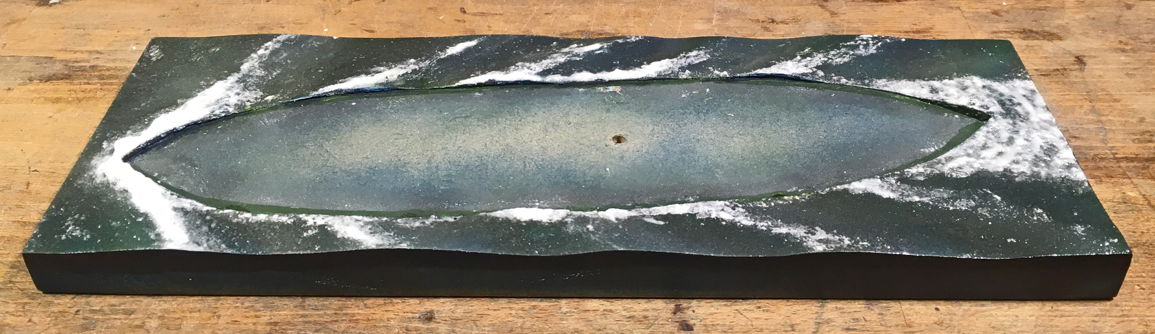
Sea-scape with wave-crests sculpted in filled acrylic gel
With the sculpting of the wave-crests and foam stirred-up complete, the sea-scape was given several more coats of gloss varnish to smooth it out, playing also with more rough areas behind breaking waves, as these should appear more matt. Assuming that the top of the waves would be more exposed to the action of wind than their front, these areas were also stippled with acrylic gel using a bristle brush, simulating the wind rippling that indicates an incoming gust of wind to the attentive sailor.
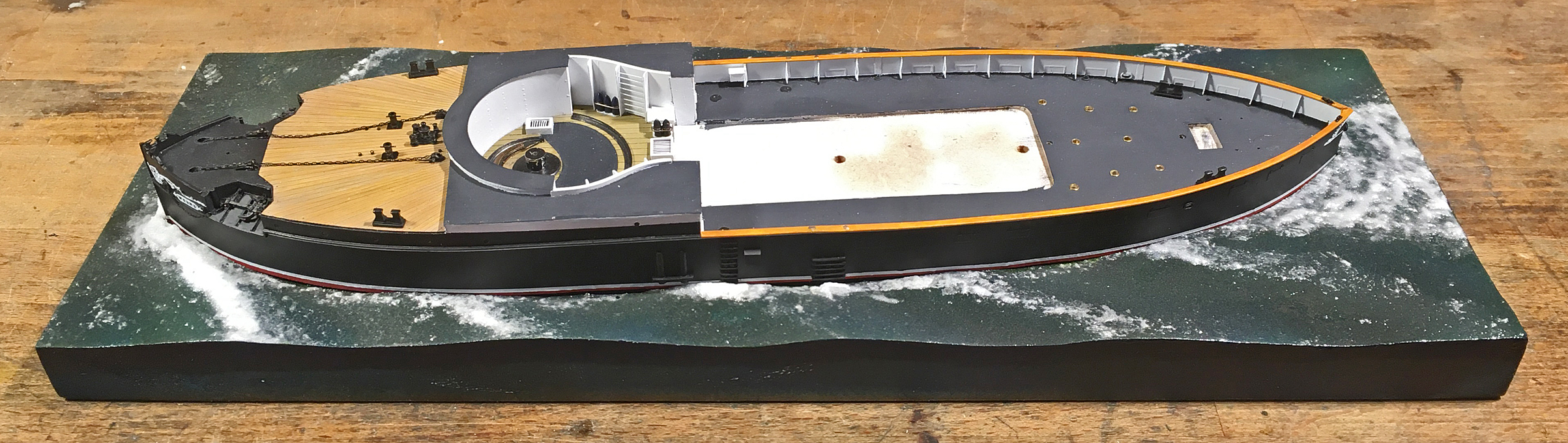
S.M.S. WESPE placed temporarily into the sea-scape
Having prepared the sea-scape in this way, the model will not yet be placed irretrievably into it. Filling the gap between the sea-scape and the model with acrylic gel will be left to the very end, so that the model can be removed, should the need arise.
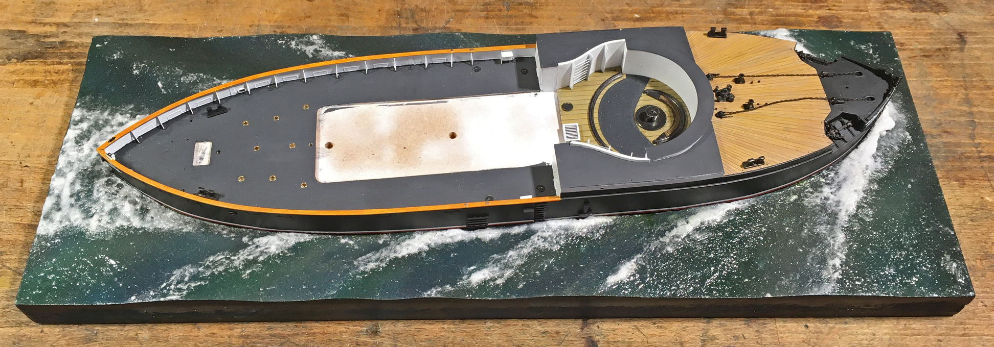
S.M.S. WESPE placed temporarily into the sea-scape
To be continued ....
***************************
Mounting the model
In another thread the question was raised as to when (permanently) mounting the model. It is a question of scale, of course, and also whether we are looking at a full-hull or a waterline-model. Smaller scale model can be very delicate, while larger scale models tend to be inherently more robust. A waterline-model may not offer you a lot of positions from which you can grab it during construction and final mounting. So, in general, it will have to be done earlier than for a full-hull model. In this particular case, adding more delicate items, particularly also those outside the hull, would make it almost impossible to handle the model without damaging it. Therefore, it was decided to prepare the mounting now.
The base-plate, a piece of 20 mm thick, MDF, forms an integral part of the display case that had been constructed earlier. To this the model will be fixed with a single wood-screw from the bottom. The hole in the model for this had been drilled early on in the construction process. I did not envisage to have to mount and unmount the model frequently, otherwise I would have embedded a threaded nut into the bread-and-butter hull and used a machine screw instead.
With hindsight, I perhaps should have extended the hull a bit more than just 2 mm below the waterline. The 2 mm are not that much to model the sea, but would translate into a wave-height of around 32 cm or a good foot.
The scenario I imagined for the presentation is that the ship moves in a rather calm sea, but at moderate speed (the max. speed of the WESPE-class was only around 10 kn anyway). The weather is fine, with sun and a light breeze � a summer day on the North Sea or the Baltic.
There is only one image I am aware off, that shows one of the boats moving, S.M.S. NATTER moving slowly along the Kiel-Kanal. Therefore, we do not really know what their wave-pattern would have looked like. The bow is quite full, it has a ram protruding below the waterline, and hard bilges with a flat bottom. In a way, this is the form of our river freighters. Therefore, I looked around on the Internet for pictures that show such ships on the move. Of course, there is a difference in wave patterns due to the restricted water depths in river channels. The wake would be more or less a Kelvin pattern with the waves radiating from the ship with an included angle of around 40�. The base is not much bigger than the ship to allow close-up view of the model, so there is actually not so much sea to model.
Base-board covered in moulded water-colour paper and primed
I decided to try something new (for me) and instead of sculpting and carving the sea from plaster of Paris, as I had done in the past, I used a sheet of thick water-colour paper. The waves were formed by placing thin scraps of acrylic foam (because I happen to have some) underneath and then gluing it down with white glue, working from the bow to the stern. The space for the model was cut out first, of course. Once the glue set, the paper was trimmed to size. The gaps under the paper were filled with acrylic wood-repair putty and the edges sanded smooth once the putty had set. At this stage also the fit of both, the model and the display case were checked and small corrections made. Finally, the whole base was given a coat of sanding filler to seal the paper and the wood. The edges were sanded smooth again.
Base colouring sealed with gloss varnish
Painting proceeded in several steps. First a coat of Schmincke AeroColor turquois acrylic was applied by airbrush. However, the paint was applied in a glancing fashion against the direction of the waves. A second coat using Vallejo ModelAir �steel blue�, again glancing, but with the waves was applied. Here in this application, it is not really apparent, but when there are shorter, steeper waves modelled this causes a colour change effect, when you look at the sea-scape from different angles. The front of the waves then was lightened up somewhat by a light spray of Schmincke AeroColor chrome-oxide green and the crest areas further lightened up with a light dust of Vallejo ModelAir �hemp� to give the sea a flatter green appearance. This base colouring was sealed by two generous coats of acrylic gloss varnish applied with a flat hairbrush.
In the next step, the wave crests were modelled using acrylic gel and gel filled with acrylic �micro-balloons�. In the past I actually used crystal sugar as a filler, which works very well, as not all crystals dissolve, but remain as transparent parts. I used this even before I became aware of acrylic gels together with wallpaper-glue and this �icing� is holding up well after 40+ years. Part of the bow-wave was sculpted again in this way.
Sea-scape with wave-crests sculpted in filled acrylic gel
With the sculpting of the wave-crests and foam stirred-up complete, the sea-scape was given several more coats of gloss varnish to smooth it out, playing also with more rough areas behind breaking waves, as these should appear more matt. Assuming that the top of the waves would be more exposed to the action of wind than their front, these areas were also stippled with acrylic gel using a bristle brush, simulating the wind rippling that indicates an incoming gust of wind to the attentive sailor.
S.M.S. WESPE placed temporarily into the sea-scape
Having prepared the sea-scape in this way, the model will not yet be placed irretrievably into it. Filling the gap between the sea-scape and the model with acrylic gel will be left to the very end, so that the model can be removed, should the need arise.
S.M.S. WESPE placed temporarily into the sea-scape
To be continued ....
Eberhard
Former chairman Arbeitskreis historischer Schiffbau e.V. (German Association for Shipbuilding History)
--------------------------------------------------------------------------------------------------------------------------------------------------------------------------------------------
Former chairman Arbeitskreis historischer Schiffbau e.V. (German Association for Shipbuilding History)
--------------------------------------------------------------------------------------------------------------------------------------------------------------------------------------------
-
Fliger747
- Posts: 5068
- Joined: Wed Jan 02, 2013 1:15 am
Re: 1:160 S.M.S. WESPE Armoured Gunboat (1876)
Thank your for showing your sea scape method, it looks very good! I have been procrastinating for decades producing this for my 1:192 Alaska, a moderately large model.
Regards: Tom
Regards: Tom