Re: chutes. I am not sure what the source of these chutes is - ie., did the spent casings exit directly from the deck into the chutes (in which case the chutes would indicate the level of the deck) or were they swept into the scuttles (each stern mount appears to have had three shell casing scuttles and a single clip scuttle) to a section below deck where they then funneled out the chutes? This latter method seems to be consistent with the other 40mm mounts.
Re: height of splinter shields. Reviewing photos of the builder's model and of the "Iowa" model (which looks more like Missouri), in addition to late-war images of Missouri, shields are shown which are significantly taller than 15" - though I do not believe they are at 56" either. So, if you take Lee's 24" offset from the published 56-inch shield height, you wind up with a height of 32" above deck - and 56" above mount floor. This would be consistent with photos I have. So maybe the 56-inch dimension is from the tub floor and not from the main deck.
It is stunning that there do not appear to be actual builder's drawings - with dimensions - of these ships!
Calling all Iowa-class (BB-61) fans
Moderators: BB62vet, MartinJQuinn, Timmy C, Gernot, Olaf Held, Dan K, HMAS, ModelMonkey
-
RandyM
- Posts: 337
- Joined: Sat Dec 15, 2007 10:40 pm
- Location: San Diego
-
Cliffy B

- Posts: 3125
- Joined: Sun Feb 01, 2009 3:55 pm
- Location: Hawaii
- Contact:
Re: Calling all USS Iowa class fans
I can grab a tape measure and jump inside the starboard gun tub on BB-64 if you guys want.
Drawing Board:
1/700 Whiff USS Leyte and escorts 1984
1/700 Whiff USN Modernized CAs 1984
1/700 Whiff ASW Showdown - FFs vs SSGN 1984
Slipway:
1/700 Whiff USN ASW Hunter Killer Group Dio 1984
1/700 Whiff USS Leyte and escorts 1984
1/700 Whiff USN Modernized CAs 1984
1/700 Whiff ASW Showdown - FFs vs SSGN 1984
Slipway:
1/700 Whiff USN ASW Hunter Killer Group Dio 1984
-
BB62vet

- Posts: 3162
- Joined: Mon Nov 18, 2013 3:41 pm
- Location: Mocksville, NC
Re: Calling all USS Iowa class fans
Randy M wrote:
Hank
My guess (based on actual firing of a dual 3"'/50 mount in combat) is that the casings were physically kicked/shoved into the chutes for ejection into the sea during firing. Those casings mount up very quickly and would have posed a hazard to the gun crew. Besides, during WWII/Korea no one cared about saving so much 40mm brass during combat ops. Training excercises, maybe so. During Vietnam, our 5"/38 spent brass was collected and returned for recycling.did the spent casings exit directly from the deck into the chutes (in which case the chutes would indicate the level of the deck) or were they swept into the scuttles (each stern mount appears to have had three shell casing scuttles and a single clip scuttle) to a section below deck where they then funneled out the chutes?
Hank
HMS III
Mocksville, NC
BB62 vet 68-69
Builder's yard:
USS STODDARD (DD-566) 66-68 1:144, Various Lg Scale FC Directors
Finished:
USS NEW JERSEY (BB-62) 67-69 1:200
USN Sloop/Ship PEACOCK (1813) 1:48
ROYAL CAROLINE (1748) 1:47
AVS (1768) 1:48
Mocksville, NC
BB62 vet 68-69
Builder's yard:
USS STODDARD (DD-566) 66-68 1:144, Various Lg Scale FC Directors
Finished:
USS NEW JERSEY (BB-62) 67-69 1:200
USN Sloop/Ship PEACOCK (1813) 1:48
ROYAL CAROLINE (1748) 1:47
AVS (1768) 1:48
-
BB62vet
- Posts: 3162
- Joined: Mon Nov 18, 2013 3:41 pm
- Location: Mocksville, NC
Re: Calling all USS Iowa class fans
Cliffy B - for arguement's sake, go ahead and do that if you can - I doubt that the floor of the tub would have been altered thru the years. The heights of the tub walls probably were in the '80s to accomodate the modern changes. That's particularly true in the case of NEW JERSEY's port after 40mm tub - that is very obvious from 1999 photos of her at Phily in mothballs.
Hank
Hank
HMS III
Mocksville, NC
BB62 vet 68-69
Builder's yard:
USS STODDARD (DD-566) 66-68 1:144, Various Lg Scale FC Directors
Finished:
USS NEW JERSEY (BB-62) 67-69 1:200
USN Sloop/Ship PEACOCK (1813) 1:48
ROYAL CAROLINE (1748) 1:47
AVS (1768) 1:48
Mocksville, NC
BB62 vet 68-69
Builder's yard:
USS STODDARD (DD-566) 66-68 1:144, Various Lg Scale FC Directors
Finished:
USS NEW JERSEY (BB-62) 67-69 1:200
USN Sloop/Ship PEACOCK (1813) 1:48
ROYAL CAROLINE (1748) 1:47
AVS (1768) 1:48
-
RandyM
- Posts: 337
- Joined: Sat Dec 15, 2007 10:40 pm
- Location: San Diego
Re: Calling all USS Iowa class fans
That (actually measuring the prototype) would be *AWESOME.* I really need the distance from the floor of the mount to the main deck, at the inboard-most point of the arc.
-
James M
- Posts: 252
- Joined: Fri Apr 01, 2005 11:30 pm
- Location: Fullerton, CA
Re: Calling all USS Iowa class fans
And to help muddy the waters a little. I found the sponson and shield drawing.
The floor of the gun tub is slightly above the knuckle.

Here is what I can make out clearly from this drawing and others on the page:
The shield is 4' 8" in height
The lower part of the shield is 3' 3" in height
From the knuckle to the top of the foundation floor is 12"
No written measurement is given for the distance from the floor to the main deck.
Taking a scale to the drawing says it is about 27"
This photo of Missouri show the weld line and the difference
http://navsource.org/archives/01/063/016300g.jpg

The spent shell casing went down the case ejection chutes and funneled into a storage compartment by the sponson.
The holes that were cut threw the shield at the base were for water drainage.
Here are the actual dimensions from the Iowa:
1) Tallest part of the shield = 56" tall
2) The lower part of the shield = 39" tall
3) Distance from the floor to the main deck = 27"
4) Distance from main deck to the tallest part of the shield = 29"
5) Distance from the knuckle to the top of the foundation floor = 15"
There is the step down cut into the shield for the crew to get in and out easier.
(Seen in photo of New Jersey below)
It is 84" long (curved) and has a 6" lip off the main deck (wood deck not included).
The passing scuttle opening is 42" tall x 45" wide.
Drawing updated to show dimensions
James
The floor of the gun tub is slightly above the knuckle.
Here is what I can make out clearly from this drawing and others on the page:
The shield is 4' 8" in height
The lower part of the shield is 3' 3" in height
From the knuckle to the top of the foundation floor is 12"
No written measurement is given for the distance from the floor to the main deck.
Taking a scale to the drawing says it is about 27"
This photo of Missouri show the weld line and the difference
http://navsource.org/archives/01/063/016300g.jpg
The spent shell casing went down the case ejection chutes and funneled into a storage compartment by the sponson.
The holes that were cut threw the shield at the base were for water drainage.
Here are the actual dimensions from the Iowa:
1) Tallest part of the shield = 56" tall
2) The lower part of the shield = 39" tall
3) Distance from the floor to the main deck = 27"
4) Distance from main deck to the tallest part of the shield = 29"
5) Distance from the knuckle to the top of the foundation floor = 15"
There is the step down cut into the shield for the crew to get in and out easier.
(Seen in photo of New Jersey below)
It is 84" long (curved) and has a 6" lip off the main deck (wood deck not included).
The passing scuttle opening is 42" tall x 45" wide.
Drawing updated to show dimensions
James
Last edited by James M on Fri Mar 20, 2015 4:24 pm, edited 6 times in total.
-
James M
- Posts: 252
- Joined: Fri Apr 01, 2005 11:30 pm
- Location: Fullerton, CA
Re: USS Iowa database / photo reference / WWII
Thank you Rick for this information. It helped me with some dates I was missing.
How much of the war log did you acquire?
Here is some more bits of information to cross reference dates, ships and photos from this web site.
http://www.fdrlibrary.marist.edu/daybyd ... 12th-1943/
November 12 1943
9:51am
The USS Iowa got underway to proceed to Hampton Roads, VA, where she was to fuel ship and be joined by her anti-submarine screening destroyers before departing on the main leg of the journey.
Because of her deep draft and the resultant restricted waters of the Chesapeake Bay, she had come to the rendezvous very light in the water.
7:12pm
The tanker USS Housatonic came alongside to starboard to fuel the USS Iowa.
7:35pm
The tanker USS Escalante moored alongside to port to assist in fueling the USS Iowa.
November 13 1943
12:06am
The USS Iowa, in company with the destroyers USS Cogswell (DD651) (Commander Destroyer Division One Hundred embarked therein), the USS Young (DD580) and the USS William D. Porter (DD579), as Task Group 27.5 with Capt. John L. McCrea as Task Group Commander, departed Hampton Roads, VA for Oran, Algeria. The USS Iowa was piloted out of the Hampton Roads area by Lt. Comdr. L. T. Stallings, US Coast Guard Reserve.
How much of the war log did you acquire?
Here is some more bits of information to cross reference dates, ships and photos from this web site.
http://www.fdrlibrary.marist.edu/daybyd ... 12th-1943/
November 12 1943
9:51am
The USS Iowa got underway to proceed to Hampton Roads, VA, where she was to fuel ship and be joined by her anti-submarine screening destroyers before departing on the main leg of the journey.
Because of her deep draft and the resultant restricted waters of the Chesapeake Bay, she had come to the rendezvous very light in the water.
7:12pm
The tanker USS Housatonic came alongside to starboard to fuel the USS Iowa.
7:35pm
The tanker USS Escalante moored alongside to port to assist in fueling the USS Iowa.
November 13 1943
12:06am
The USS Iowa, in company with the destroyers USS Cogswell (DD651) (Commander Destroyer Division One Hundred embarked therein), the USS Young (DD580) and the USS William D. Porter (DD579), as Task Group 27.5 with Capt. John L. McCrea as Task Group Commander, departed Hampton Roads, VA for Oran, Algeria. The USS Iowa was piloted out of the Hampton Roads area by Lt. Comdr. L. T. Stallings, US Coast Guard Reserve.
-
Scale Shipyard / W.L.U.
- Scale Shipyard

- Posts: 60
- Joined: Wed Mar 23, 2005 3:19 pm
- Location: Long Beach Ca.
- Contact:
Re: Calling all USS Iowa class fans
Gee James.....That drawing looks familiar. 
W.L. Upshaw
The Scale Shipyard
World's Largest Supplier of Large Scale Warship Hulls and Fittings
http://www.scaleshipyard.com
The Scale Shipyard
World's Largest Supplier of Large Scale Warship Hulls and Fittings
http://www.scaleshipyard.com
-
BB62vet
- Posts: 3162
- Joined: Mon Nov 18, 2013 3:41 pm
- Location: Mocksville, NC
Re: Calling all USS Iowa class fans
I stand corrected on the disposition of empty casings via the (3) 24" oval floor scuttles in the after tubs - they are connected to 24" wide conduits below the tub level into the void areas on either side of the stern (C-221V & C220V) as shown in the photo below from the Booklet of General Plans (MISSOURI - 1950).
As you can see, all three scuttles (at 45 deg. apart) allow the casings to be sent to one common entry into the void compartment for collection.
One other point regarding the Main Deck level w/Tubs - The external boxes at the aft end of the tubs (port/stbd) are called Freeing Ports in the MISSOURI PLAN BOOK - not sure what those are, but I don't believe they were ventilation ducts as W.L. has mentioned. If they were vent. ducts they would have been called out as such. As they are external to the tub, there is no visible connection to the floor of the tub, only the tub shield at the point of connnection. No indication on the plan view as to an opening, grate, or other sort of penetration from the tub to the port. I agree with Randy that a detail of this part that was an actual construciton drawing would clear this up once and for all. And finally, James M is correct in his shield wall heights according to the Stern Plan Drawing in the Plan Book on pg. 101 - 3'-3" and 4'-8".
Hope this somewhat clears up a couple points.
Hank
One other point regarding the Main Deck level w/Tubs - The external boxes at the aft end of the tubs (port/stbd) are called Freeing Ports in the MISSOURI PLAN BOOK - not sure what those are, but I don't believe they were ventilation ducts as W.L. has mentioned. If they were vent. ducts they would have been called out as such. As they are external to the tub, there is no visible connection to the floor of the tub, only the tub shield at the point of connnection. No indication on the plan view as to an opening, grate, or other sort of penetration from the tub to the port. I agree with Randy that a detail of this part that was an actual construciton drawing would clear this up once and for all. And finally, James M is correct in his shield wall heights according to the Stern Plan Drawing in the Plan Book on pg. 101 - 3'-3" and 4'-8".
Hope this somewhat clears up a couple points.
Hank
HMS III
Mocksville, NC
BB62 vet 68-69
Builder's yard:
USS STODDARD (DD-566) 66-68 1:144, Various Lg Scale FC Directors
Finished:
USS NEW JERSEY (BB-62) 67-69 1:200
USN Sloop/Ship PEACOCK (1813) 1:48
ROYAL CAROLINE (1748) 1:47
AVS (1768) 1:48
Mocksville, NC
BB62 vet 68-69
Builder's yard:
USS STODDARD (DD-566) 66-68 1:144, Various Lg Scale FC Directors
Finished:
USS NEW JERSEY (BB-62) 67-69 1:200
USN Sloop/Ship PEACOCK (1813) 1:48
ROYAL CAROLINE (1748) 1:47
AVS (1768) 1:48
-
RandyM
- Posts: 337
- Joined: Sat Dec 15, 2007 10:40 pm
- Location: San Diego
Re: Calling all USS Iowa class fans
That is an excellent drawing - I have the plan book and have never noticed it. Makes you wonder - how did that shell casing void get emptied? Was that some sailor's battlestation - to collect casings from that void and dispose of them elsewhere?
So we are all in agreement that the shield height is a max of 56". The plans I have show very clearly how the shield tapers down to other heights, and those seem to correlate well with photos of the builder's model. HOWEVER, I do not believe the shield is 56" high from the main deck, and that is something no one can measure since the shield has been significantly cut down over time.
But if we can get a real measurement of the floor of the tub to the main deck, then I could mock-up a 56"-high shield (with respect to the tub floor) and see how well it matches photos.
Below is one of the most interesting photos I've found of this area. If you look at the starboard mount's deck WRT the main deck, it is obviously offset lower. But if you look at the shield height WRT to, for example the nearby chocks, it just doesn't seem possible that it is nearly five-feet off the maindeck. This high of a shield would be nearly seven feet tall when standing in the mount. Looking at the ammo racks in the port mount - they seem to be the same as all the other mounts (ie., four rows of racks at the tallest part of the shield). And none of the other mounts' shields are seven-feet tall. So in summary it seems the mount's deck is offset ~ 24-inches from the main deck, and the mount's shield is a maximum of 56" tall from the mount's deck. All I need now is for Cliffy to verify the distance between the main and mount decks.
Then finally is the question of the cutout in the shield. I have photos which clearly show the shield dipping down to nearly deck level at the inboard-most point on the arc. It appears to be an entry point for the mount crew. Not all ships seem to have had this cutout, and the Trumpeter kit part avoids it completely. Unfortunately in this photo it is obscured by the gun itself (assuming this is Missouri in the first place).

So we are all in agreement that the shield height is a max of 56". The plans I have show very clearly how the shield tapers down to other heights, and those seem to correlate well with photos of the builder's model. HOWEVER, I do not believe the shield is 56" high from the main deck, and that is something no one can measure since the shield has been significantly cut down over time.
But if we can get a real measurement of the floor of the tub to the main deck, then I could mock-up a 56"-high shield (with respect to the tub floor) and see how well it matches photos.
Below is one of the most interesting photos I've found of this area. If you look at the starboard mount's deck WRT the main deck, it is obviously offset lower. But if you look at the shield height WRT to, for example the nearby chocks, it just doesn't seem possible that it is nearly five-feet off the maindeck. This high of a shield would be nearly seven feet tall when standing in the mount. Looking at the ammo racks in the port mount - they seem to be the same as all the other mounts (ie., four rows of racks at the tallest part of the shield). And none of the other mounts' shields are seven-feet tall. So in summary it seems the mount's deck is offset ~ 24-inches from the main deck, and the mount's shield is a maximum of 56" tall from the mount's deck. All I need now is for Cliffy to verify the distance between the main and mount decks.
Then finally is the question of the cutout in the shield. I have photos which clearly show the shield dipping down to nearly deck level at the inboard-most point on the arc. It appears to be an entry point for the mount crew. Not all ships seem to have had this cutout, and the Trumpeter kit part avoids it completely. Unfortunately in this photo it is obscured by the gun itself (assuming this is Missouri in the first place).
-
Fliger747
- Posts: 5068
- Joined: Wed Jan 02, 2013 1:15 am
Re: Calling all USS Iowa class fans
Randy
Zoom in on your photo, you can see the edge of the cutout just to the right of the side of the gun shield. Also note the door for the passage of ammo from the clipping room, the cupola apparently hiding under the director tub.
Zoom in on your photo, you can see the edge of the cutout just to the right of the side of the gun shield. Also note the door for the passage of ammo from the clipping room, the cupola apparently hiding under the director tub.
-
BB62vet
- Posts: 3162
- Joined: Mon Nov 18, 2013 3:41 pm
- Location: Mocksville, NC
Re: Calling all USS Iowa class fans
RandyM, et al:
A couple of points -
1) The photo shown is USS NEW JERSEY on 24 Jun 45 during Inclining Experiments (BuShps #94333 - NavSource).
2) The tub shields appear to be a one piece affair that has a personnel opening on the inboard side of each tub. This shield rises from slightly above main deck level in the aft, outward and up to it's full height above the main deck on its fwd side, curving back inboard and aft. Your picture shows this to some extent. These shields were capped with a lip, common to all the 40mm tubs.
I am checking all my 1967-69 photos & refs. to see if NEW JERSEY had her port tub altered (height-wise) to accomodate the Helo Refueling Equpment installed at that period of service. The modern ships can't really be used for reference as their tubs have been radically altered in height & so forth. Their floors, however, have not changed and Cliffy B should be able to give us a a good dimension of the difference between tub floor and main deck.
Hank
A couple of points -
1) The photo shown is USS NEW JERSEY on 24 Jun 45 during Inclining Experiments (BuShps #94333 - NavSource).
2) The tub shields appear to be a one piece affair that has a personnel opening on the inboard side of each tub. This shield rises from slightly above main deck level in the aft, outward and up to it's full height above the main deck on its fwd side, curving back inboard and aft. Your picture shows this to some extent. These shields were capped with a lip, common to all the 40mm tubs.
I am checking all my 1967-69 photos & refs. to see if NEW JERSEY had her port tub altered (height-wise) to accomodate the Helo Refueling Equpment installed at that period of service. The modern ships can't really be used for reference as their tubs have been radically altered in height & so forth. Their floors, however, have not changed and Cliffy B should be able to give us a a good dimension of the difference between tub floor and main deck.
Hank
HMS III
Mocksville, NC
BB62 vet 68-69
Builder's yard:
USS STODDARD (DD-566) 66-68 1:144, Various Lg Scale FC Directors
Finished:
USS NEW JERSEY (BB-62) 67-69 1:200
USN Sloop/Ship PEACOCK (1813) 1:48
ROYAL CAROLINE (1748) 1:47
AVS (1768) 1:48
Mocksville, NC
BB62 vet 68-69
Builder's yard:
USS STODDARD (DD-566) 66-68 1:144, Various Lg Scale FC Directors
Finished:
USS NEW JERSEY (BB-62) 67-69 1:200
USN Sloop/Ship PEACOCK (1813) 1:48
ROYAL CAROLINE (1748) 1:47
AVS (1768) 1:48
-
Cliffy B
- Posts: 3125
- Joined: Sun Feb 01, 2009 3:55 pm
- Location: Hawaii
- Contact:
Re: Calling all USS Iowa class fans
Alrighty, here goes!
The shield itself measured 3/4" thick. Subtract the paint (no clue how many layers) and you have I don't know. always thought they were 1/2" shields but I find it hard to believe there's a full 1/4" of paint on them. We don't have that much paint on any exterior surface.
The raised base plate of the old 40mm mount complete with bolts still present holding I guess a cover plate? It measured 72 5/8" diameter and 1 1/4" high.
Case chutes were 15 1/2" x 7 1/4" and were 5" from the tub wall.
Height of the STBD tub wall at its lowest point (port side) was 38", FWD side was 56" and STBD (outboard over the water) was 40" measured from the deck of the interior of the tub.
The diameter of the whole tub, wall included measured about 218 3/4".
The one measurement I DIDN'T get was the difference between the Main Deck and the lowest point of the tub which is what you wanted. I'll get that on Thursday...sorry
For photos of both gun tubs see here: viewtopic.php?f=12&t=153523&start=40#p653110
The shield itself measured 3/4" thick. Subtract the paint (no clue how many layers) and you have I don't know. always thought they were 1/2" shields but I find it hard to believe there's a full 1/4" of paint on them. We don't have that much paint on any exterior surface.
The raised base plate of the old 40mm mount complete with bolts still present holding I guess a cover plate? It measured 72 5/8" diameter and 1 1/4" high.
Case chutes were 15 1/2" x 7 1/4" and were 5" from the tub wall.
Height of the STBD tub wall at its lowest point (port side) was 38", FWD side was 56" and STBD (outboard over the water) was 40" measured from the deck of the interior of the tub.
The diameter of the whole tub, wall included measured about 218 3/4".
The one measurement I DIDN'T get was the difference between the Main Deck and the lowest point of the tub which is what you wanted. I'll get that on Thursday...sorry
For photos of both gun tubs see here: viewtopic.php?f=12&t=153523&start=40#p653110
Drawing Board:
1/700 Whiff USS Leyte and escorts 1984
1/700 Whiff USN Modernized CAs 1984
1/700 Whiff ASW Showdown - FFs vs SSGN 1984
Slipway:
1/700 Whiff USN ASW Hunter Killer Group Dio 1984
1/700 Whiff USS Leyte and escorts 1984
1/700 Whiff USN Modernized CAs 1984
1/700 Whiff ASW Showdown - FFs vs SSGN 1984
Slipway:
1/700 Whiff USN ASW Hunter Killer Group Dio 1984
-
Fliger747
- Posts: 5068
- Joined: Wed Jan 02, 2013 1:15 am
Re: Calling all USS Iowa class fans
Hopefully CliffyB isn't being suspected as a Naval Spy, running around with tape and notebook!
I believe 3/4" STS steel was fairly standard splinter protection, maybe enough to keep out .50 cal and equivalent. My recollection is that the Fletcher's were plated midships with 3/4". STS as some minimal protection to machinery spaces from strafers... Friedmans Destroyers?
Good info! thanks all.
I believe 3/4" STS steel was fairly standard splinter protection, maybe enough to keep out .50 cal and equivalent. My recollection is that the Fletcher's were plated midships with 3/4". STS as some minimal protection to machinery spaces from strafers... Friedmans Destroyers?
Good info! thanks all.
-
RandyM
- Posts: 337
- Joined: Sat Dec 15, 2007 10:40 pm
- Location: San Diego
Re: Calling all USS Iowa class fans
Cliffy... this is PERFECT. I never would have guessed Wisconsin's shields remain intact as-built (or at least close). And the photos show everything I was looking for - simply excellent, THANK YOU.
Now if you could just get that maindeck offset...
Randy
Now if you could just get that maindeck offset...
Randy
-
RandyM
- Posts: 337
- Joined: Sat Dec 15, 2007 10:40 pm
- Location: San Diego
Re: Calling all USS Iowa class fans
So here is what I've mocked-up based on Cliffy's data (along with the drawings and docs everyone else supplied). This uses an offset of 24-inches. Cliffy, while drawing this it dawned on me (think Homer Simpson "D'oh!") that all you need to measure now is from main deck to top of tallest point of shield - this will lock everything in.
At any rate, this model tracks well with the photos I have...

At any rate, this model tracks well with the photos I have...
-
BB62vet
- Posts: 3162
- Joined: Mon Nov 18, 2013 3:41 pm
- Location: Mocksville, NC
Re: Calling all USS Iowa class fans
First, Thanks Cliffy B - good info and nice photos!!!
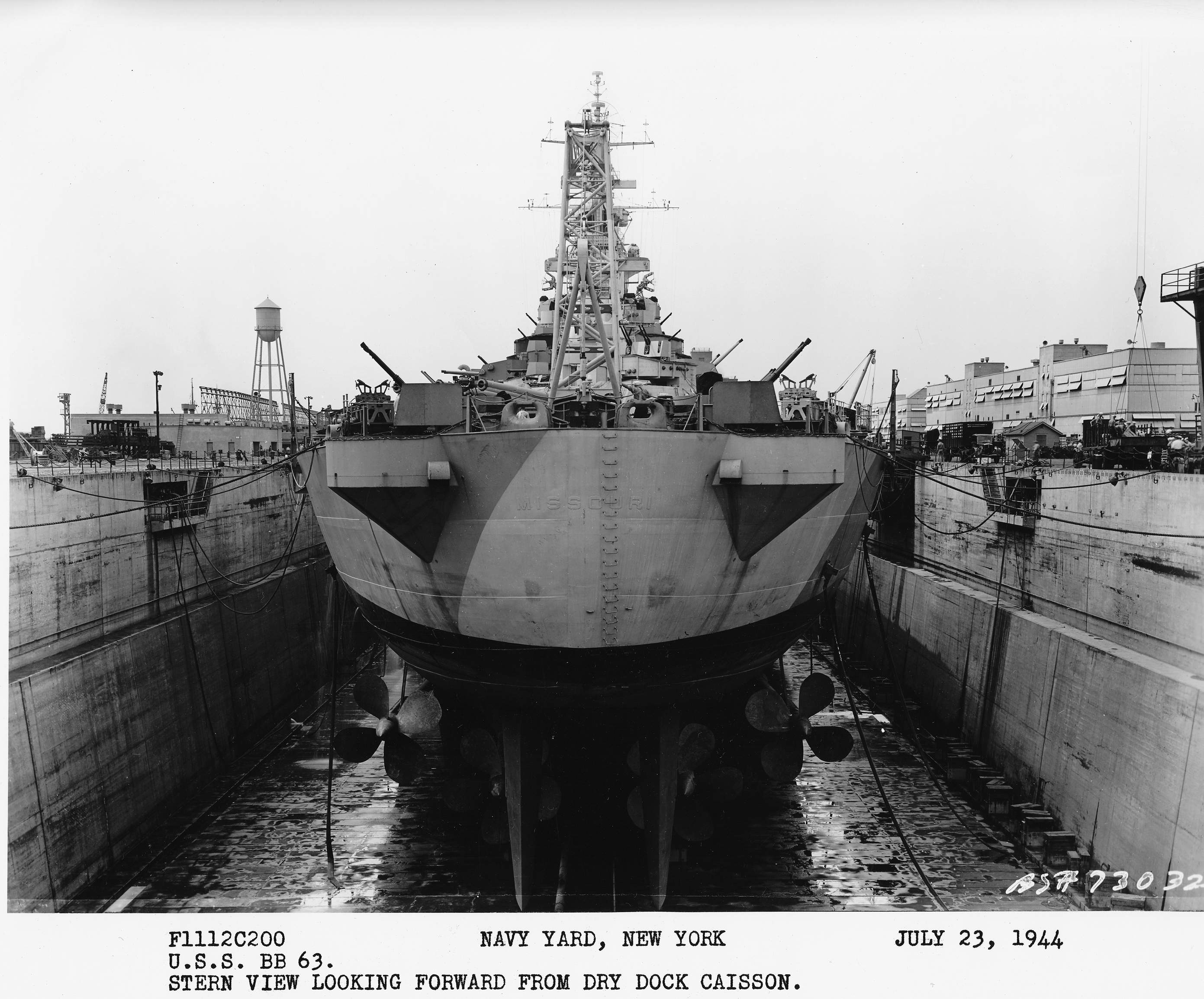
Randy - In comparison with the photos of MISSOURI in drydock and NEW JERSEY's overhead stern shot, I'm only seeing the tops of the after side of both tubs as being closer to the edge of the hull than your model portrays. Looking at the NEW JERSEY photo - port tub - the closest lifeline stanchion is approx. 3' high (3 lifelines 12" apart?) - the tub shield crosses the stanchion just above the lowest lifeline and appears the same on the stbd. side, as well. This is also apparant even moreso in the MISSOURI photo. Both tubs (from the stern) appear to be level with the stern of the hull rather than above the lip of the hull. Once again, the two ships are constructed differently, it appears.
I know this simply confuses the issue.
Hank
Randy - In comparison with the photos of MISSOURI in drydock and NEW JERSEY's overhead stern shot, I'm only seeing the tops of the after side of both tubs as being closer to the edge of the hull than your model portrays. Looking at the NEW JERSEY photo - port tub - the closest lifeline stanchion is approx. 3' high (3 lifelines 12" apart?) - the tub shield crosses the stanchion just above the lowest lifeline and appears the same on the stbd. side, as well. This is also apparant even moreso in the MISSOURI photo. Both tubs (from the stern) appear to be level with the stern of the hull rather than above the lip of the hull. Once again, the two ships are constructed differently, it appears.
I know this simply confuses the issue.
Hank
HMS III
Mocksville, NC
BB62 vet 68-69
Builder's yard:
USS STODDARD (DD-566) 66-68 1:144, Various Lg Scale FC Directors
Finished:
USS NEW JERSEY (BB-62) 67-69 1:200
USN Sloop/Ship PEACOCK (1813) 1:48
ROYAL CAROLINE (1748) 1:47
AVS (1768) 1:48
Mocksville, NC
BB62 vet 68-69
Builder's yard:
USS STODDARD (DD-566) 66-68 1:144, Various Lg Scale FC Directors
Finished:
USS NEW JERSEY (BB-62) 67-69 1:200
USN Sloop/Ship PEACOCK (1813) 1:48
ROYAL CAROLINE (1748) 1:47
AVS (1768) 1:48
-
Rick E Davis
- Posts: 3882
- Joined: Thu May 29, 2008 8:02 pm
Re: USS Iowa database / photo reference / WWII
I took digital camera shots of some pages of USS IOWA's War Diary, but not all of them during this period. I also took notes as I went along. My interest was figuring out WHICH USN destroyers (and any cruisers that also did) escorted USS IOWA on this mission and why from what I knew, they were changed out. There were a number of brand-new FLETCHERS involved and I wondered if any went into the MED with USS IOWA, they didn't (veteran BENSON-GLEAVES units were assigned that task). I also, spot checked the War Diaries of several of the destroyers I knew were involved before I looked in USS IOWA's War Diary.
I found out that to make the trip as quick as possible, there was NO oiler assigned to the Task Force and USS IOWA didn't slowdown to refuel the escorts. So the USN would detach the escorts with a new batch of escorts so that they could refuel elsewhere far away from USS IOWA. Plus, there were times when an escort would leave the Task Force and send messages far away from the Task Force before returning to it. The closer they got to Africa Escort Carriers provided air cover from a distance; on 16 November USS BLOCK ISLAND (CVE-21) (she was escorting westbound Convoy GUS-220) and on 17 November, USS SANTE (CVE-29). Security was most important and radio silence from USS IOWA was maintained.
A little correction to your 13 November entry, USS IOWA departed Hampton Roads, but she met up with DesDiv 100 outside of Hampton Roads when they "officially" formed TF 27.5.
I found out that to make the trip as quick as possible, there was NO oiler assigned to the Task Force and USS IOWA didn't slowdown to refuel the escorts. So the USN would detach the escorts with a new batch of escorts so that they could refuel elsewhere far away from USS IOWA. Plus, there were times when an escort would leave the Task Force and send messages far away from the Task Force before returning to it. The closer they got to Africa Escort Carriers provided air cover from a distance; on 16 November USS BLOCK ISLAND (CVE-21) (she was escorting westbound Convoy GUS-220) and on 17 November, USS SANTE (CVE-29). Security was most important and radio silence from USS IOWA was maintained.
A little correction to your 13 November entry, USS IOWA departed Hampton Roads, but she met up with DesDiv 100 outside of Hampton Roads when they "officially" formed TF 27.5.
-
RandyM
- Posts: 337
- Joined: Sat Dec 15, 2007 10:40 pm
- Location: San Diego
Re: Calling all USS Iowa class fans
Here's the current state of the aft tub reconstruction. The one on the starboard side is a do-over: I'm not happy with the shape. For the port side I got more serious and printed out a template from the modeled part, traced that onto sheet styrene and cut it out. You'd think I'd live by one of my own mottos (there's never time to do it right but there's always time to do it over).
I shimmed the floor piece with 0.010" sheet, then added supports underneath to bring it up to the correct height. The tub floor now sits 27" below the maindeck, and the shield is 56" above the tub floor.
Thanks to everyone who helped solve this latest crisis
Next up is to add the ammo cupola.
Randy

I shimmed the floor piece with 0.010" sheet, then added supports underneath to bring it up to the correct height. The tub floor now sits 27" below the maindeck, and the shield is 56" above the tub floor.
Thanks to everyone who helped solve this latest crisis
Next up is to add the ammo cupola.
Randy
-
BB62vet
- Posts: 3162
- Joined: Mon Nov 18, 2013 3:41 pm
- Location: Mocksville, NC
Re: Calling all USS Iowa class fans
Randy M -
Very nice - I think they came out as well as you could expect. Perhaps a bit of smoothing on the stbd side upper lip and you will have it!
Isn't it amazing that there are so many nuances in a single class of ship? All are not the same!!
Hank
Very nice - I think they came out as well as you could expect. Perhaps a bit of smoothing on the stbd side upper lip and you will have it!
Isn't it amazing that there are so many nuances in a single class of ship? All are not the same!!
Hank
HMS III
Mocksville, NC
BB62 vet 68-69
Builder's yard:
USS STODDARD (DD-566) 66-68 1:144, Various Lg Scale FC Directors
Finished:
USS NEW JERSEY (BB-62) 67-69 1:200
USN Sloop/Ship PEACOCK (1813) 1:48
ROYAL CAROLINE (1748) 1:47
AVS (1768) 1:48
Mocksville, NC
BB62 vet 68-69
Builder's yard:
USS STODDARD (DD-566) 66-68 1:144, Various Lg Scale FC Directors
Finished:
USS NEW JERSEY (BB-62) 67-69 1:200
USN Sloop/Ship PEACOCK (1813) 1:48
ROYAL CAROLINE (1748) 1:47
AVS (1768) 1:48