Page 2 of 4
Re: Calling all Essex Class Carrier Fans!
Posted: Tue Apr 01, 2008 3:18 pm
by Capt652
CV-38 Update
After spring break hiatus time to get back to work!
I'm still making my way through the port side flight deck overhang. Very few pictures to go on. And ATOS plans don't show the visible details. I didn't want to simply guess on what to scratch build. I'm good with how this section came out. There are Spaces (ammo ready rooms, etc...), platforms, walkways, and voids. I tried to replicate corrugated walkways with parallel .010"x.020" evergreen strips. Platforms look like typical construction with bracing. Voids were easy!!! I still may tweak a little more.
Capt652
Re: Calling all Essex Class Carrier Fans!
Posted: Wed Apr 02, 2008 3:10 pm
by ModelMonkey
Superb! The exterior vent detail really stands out too. That'll be one conspicuous difference between yours and the Yorktown I'm building.
Re: Calling all Essex Class Carrier Fans!
Posted: Fri Apr 04, 2008 6:13 am
by raser13
this is just a nooby question. but, what is the copper or brass piping that you guys use on the out side of the hull? i'm guessing it's for the "gutters"? like in the pics two posts back, the pipe thats under(or above in the pic since it's upside down) the bay doors. sorry if i'm getting what the items actually are i have never been nautical i'm building this up as a present and learning the hole way.
Re: Calling all Essex Class Carrier Fans!
Posted: Thu Apr 10, 2008 3:10 pm
by Capt652
Sorry raser13 for such a long wait for this answer...
To tell the truth I really don't know what the term 'gutter' means but the parts I added to my build is just plain old wire from the hardware store. I used .020" copper wire for the external fuel lines on the port side. I don't know what gauge .020" would be- I had thrown away the package so I checked it with a micrometer. On the starboard side I used some heavy 18 gauge copper wire near where the starboard hanger deck catapult would have been on earlier ships. I'm not exactly sure what that pipe represents but my guess is a large diameter hose for replenishment of fuel oil? I do know the Shangri-la wasn't the only ship that that large tube can be seen. I have also used some fine diameter steel wire on the island to represent electrical wiring.
On a different note;
I ordered a reprint of the photo of Shangri-la coming along side the USS Attu from the Naval Historical Center Photographic Center. The photo has pretty good resolution and therefore I found more details that I missed before having a clear picture. So now I am re-doing some details on the starboard bow area. Catwalks were eliminated (after I already spent a great deal of time making catwalks to match a '44 picture), and other small details can be seen that I want to show. I have to try to build some whip antenna mounting bases. The bases appear to project out just below the flight deck catwalks both very near the #2 lattice antenna and also along the flight deck aft replacing those lattice antennas. Pictures of the Randolph kamikaze damage and some photos of the Boxer show similar mounts and those will be my guide.
CV-38 Update
Posted: Mon May 26, 2008 10:28 am
by Capt652
Hi all!
Been working on the fantail after receiving some great photos of Shangri-la that I hadn't seen before. I'm still not happy with the layout of the Trumpeter model but I'm not going to scratch build this whole area to make a correction. The first platform above the main deck is too far above the main deck on the model and that upper bulkhead should drop more below the flight deck! Anyway I did a refit on details I had already completed to add bracing and structure that is unique to Shangri-la. Here is a picture I recently acquired;
And here is my work;
I spent a few days reshaping the rear sponson. The Trumpy piece didn't have the required drop below the railing (where the ship's name is displayed). The outriggers which show up on both sides of the sponson are something unique to Shangri-la - at least I haven't noticed them on any other carrier.
Capt652
Re: Calling all Essex Class Carrier Fans!
Posted: Mon May 26, 2008 1:38 pm
by Essex
Capt, it's a very nice work!

We find more and more inaccuracies on Trumpy's Essex.

It seems to me that the vertical support at the first platform's edge is too close to the girder.
raser13 wrote:but does anyone know if the hawsereels and the manilila rope reel are on the starboard side of the ship as well. or are they only on the port side like shown in the diagram? i have already installed the ones on the port side. these is the only sticking points left on this area of the ship,minus railings and ladders.(waiting patiently for those to arive in the mail)
That interests me too, I was waiting for Tracy's answer, but maybe it's a top secret?

Or you got an answer in a mail? There are some drawings in the Raven's book, but all are different.
On the page 47 (Essex, top view and side view) can be seen six manilla rope reels and two hawser reels. The manilla rope reels are both side at the rear of the front wall and behind both girders, the hawse reels both side behind the first girder at a 45 degree angle.
On the page 57 (Randolph, side view only) it seems to be the same configuration as on the AOTS drawing D2, i.e. two manilla rope reels and four hawser reels, maybe both port and starboard side.
On the page 65 (Lexington, top view only) there are only four manilla rope reels, starboard side at the rear of the front wall, port side behind the first grider and both side behind the second girder. The two hawser reels are on the same position as at the Essex's drawing.
...and what is with the Yorktown after her 1944 refit?

Re: CV-38 report
Posted: Thu Jun 12, 2008 11:33 am
by Capt652
Hi all,
I've been working on a few details on the hanger deck. I noticed a small folding platform off the edge of the deck directly under where the boom of the davit crane would swing fore and aft. I quick look at Navsource found that a lot, but not all essex class carriers had them. CV-11,12,13,14,15,19,20 and 38 had either one or both. They are shown both flat and folded upright. I am wondering and looking for some help as to whether there were railing around them. If these platforms did have some type of railing then of course they would have to be removeable or would have to stow in such a way to allow the platform to fold. Has any one seen these up close and could answer this question?
That large diameter round stock attached to the side of the hull under the forward davit crane area is also a mystery for me. I came across a picture in the Shangri-la cruise book showing planes being loading on board by that davit crane. The forward end of that large tubing is visible and one can see three smaller pipes or conduit exiting out and turning into the hull. So is this large diameter 'thing' a conduit to protect wiring or piping?
Here are two pics of my work
Capt652
Re: Calling all Essex Class Carrier Fans!
Posted: Thu Jun 12, 2008 11:47 am
by Tracy White
I don't have any really good shots of those platforms when up; when down for replenishment there's obviously no railings around. I would imagine there would be railings even when those were folded up, it's probably easier than having separate runs that you have to tie down at the ends, where they platform folded up.
In regards to the piping, those are fuel lines. You see them on the port side as well; it was safer to run them outside the hull where any knicks or cuts would vent or discharge over the side rather than into the ship. Those particular ones probably ran to refueling stations on the hangar deck and forward starboard flight deck. I've got some textual descriptions of the hangar deck locations but no photos yet so I'm not sure how they were piped through.
Re: Calling all Essex Class Carrier Fans!
Posted: Thu Jun 12, 2008 1:14 pm
by raser13
hey capt. i dont know if this pic will help at all it's of the cvs 21. it looks to have your dec in the down position with chain railings around it. i dont have anyting in the up position. sorry.
http://www.myrtsweb.com/upload/raser13/ ... 2adeck.jpg
did a link so the pic could be bigger.
Re: Calling all Essex Class Carrier Fans!
Posted: Thu Jun 12, 2008 7:23 pm
by Capt652
Tracy and raser13 thanks for the help!
In regards to that railing I would imagine that the PE railing that looks like chain strung would be closest to represent that area. I am using Gold Metal Models Essex PE and I should probably switch to that type in that area. That picture of CV-21 is perfect to see detail, Thanks again raser13!
For the sake of conversation, Tracy don't you think that the fuel line layout is rather weird? Why would the conduit for these lines be routed so indirectly to move from aft to forward? The picture I referred to clearly shows three lines exiting the larger conduit at the front and turning in to the hull. Two of those lines look to be approx. 8"-10" diameter and the other is a lot smaller, maybe electrical in nature.
I wish I could post this particular pic but it is from a cruise book I bought with a VERY bold warning not to re-distribute any material. Anyway I can understand the reasoning in keeping the fuel outside the ship as much as possible. In this particular area the threat of damage to the lines from crane operations is probably pretty likely. But why the drop between points? Shangri-la isn't the only carrier with that configuration for these fuel lines.
Just wondering...
Capt652
Re: Calling all Essex Class Carrier Fans!
Posted: Thu Jun 12, 2008 8:31 pm
by Tracy White
You see it on the port side to go around sponsons... routed early and then left in place when the sponsons for the hangar cats were removed. Honestly, I don't have access to the plans to tell you WHY they were routed the way they were.
CV-38 Update
Posted: Mon Jul 07, 2008 9:14 pm
by Capt652
Hi all! Happy Birthday USA!
I've been working on the paravane tracks after the recent discussion on the subject. The pictures submitted in the posts showed some collective detail which, I believe represents the essex class build. I had purchased the L'Arsenal paravanes which are certainly much better than that supplied by Trumpeter. And I had also long ago mistakenly glued them to the fantail area... not the L'Arsenal, the trumpy ones which will have to stay. I looked around the hobby shops for some square stock brass, the closest look to what I believe were steel I-beam tracks. But I had no luck finding anything. So I used 22 gauge steel wire and ground the outside flat. I plan to also add vertical bracing after my flight deck is glued down the final time.
And a view of the L'Arsenal paravane
Capt652
Re: Calling all Essex Class Carrier Fans!
Posted: Mon Jul 07, 2008 10:17 pm
by gtb -red
1:350 CV-38 Shangri-la 1945
Posted: Sun Aug 10, 2008 1:07 pm
by Capt652
Hi all-
More work on the stern and starboard aft sections. After some talk in the CASF Essex-class area regarding the shape of the rear sponson I re-worked mine. The top edge of the sponson was not straight across as molded on the trumpeter model, so I removed the top rolled edge I had already applied and cut down the height. From forward to aft the height did increase as the splinter shield changed from longitudinal to transverse to a point just before the radius changed to the straight transverse behind the railing. The hard part was bending the wire to match the new slope. I also changed the railing on the main deck on the starboard side where it meets the large bulkhead. The Shangri-la had a short (railing height) bulkhead that ran transverse toward centerline a few feet. Between it and the large bulkhead I used GMM PE railing that represents removable chain links.
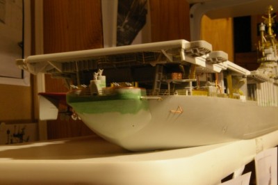
The starboard aft area from main deck up to the flight deck overhang needed a lot of detail. I had commented already about the potato lockers and piping on the Intrepid (AOTS Intrepid pictures and plans)and whether the two were ralated; with very few pictures in my possession of Shangri-la and just a couple pictures of that area of any of the other Essex-class carriers I worked out some details. Piping, vents, conduit, stairways, and structures were added. I used the ATOS Intrepid and the Raven Essex-class Carrier plans for the stairway. I gathered from the plans that the earlier carriers had the stairway start at the main deck away from the bulkhead and the later built ships with the first stair run against the bulkhead (minor detail).
Capt652
Re: 1/350 USS Shangri La CV-38 (1945) - Trumpeter
Posted: Tue Sep 02, 2008 3:26 pm
by Capt652
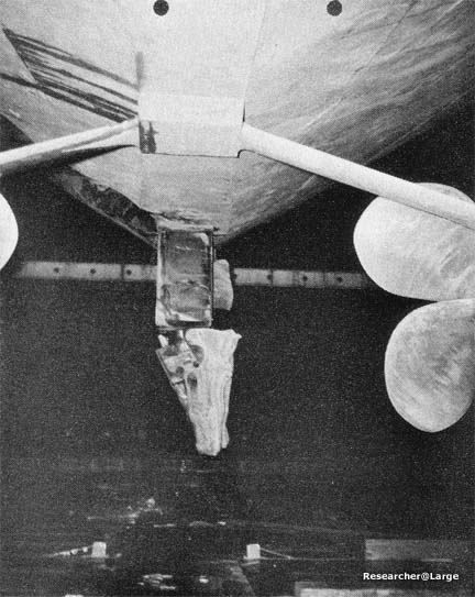
Back to work after having to take holiday while the sun is warm and camping is the thing to do... anyway I worked a little on the struts for the prop shafts. The Trumpy kit is lacking the detail that the essex class carriers had. Their single strut in real use wouldn't adequately hold a prop shaft turning with the potential of 150,000 shaft horsepower (or is it 150,000/4 per shaft?). The bracing I created is close to the look of the real ships. At Researchers@Large Tracy posted pictures of Intrepid in dry dock after torpedo damage to the rudder and fantail. This picture shows clearly the attachment of strut to hull for the center screws.
http://www.researcheratlarge.com/Ships/CV11/Photo75.jpg
I also found this picture of Shangri-la's prop shaft configuration.
download/file.php?id=3634&mode=view
And here is what I came up with...
I think I'll try some white glue (Elmers) to see if I can add a radius to the point of attachment of strut to prop bearing.
Capt652
Re: 1/350 USS Shangri La CV-38 (1945) - Trumpeter
Posted: Fri Sep 19, 2008 1:35 pm
by Capt652
Hi all!
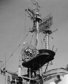
Final work on the island... After studying pictures of Shangri-la taken in 1947 at PSNY that are very clear, and comparing those to pictures of Shangri-la in Sept.- Oct. 1945 that are quite blurry, I am now comfortable with building the final details of the island structure, especially the masts, antenna, and radar. I'm trying to be accurate with this area as probably all essex class carriers were different and simply by glancing at the island one can identify each ship. (I think everyone that his spent time scratch building these tiny parts have spent a far share on their knees trying to find one in the carpet - I know I have!!!) Firstr is a picture from PSNY and then my representation.
- cv-38111.jpg (15.14 KiB) Viewed 5737 times
Capt652
Re: 1/350 USS Shangri La CV-38 (1945) - Trumpeter
Posted: Fri Sep 19, 2008 1:39 pm
by Capt652
Re: 1/350 USS Shangri La CV-38 (1945) - Trumpeter
Posted: Fri Sep 19, 2008 3:18 pm
by FlyingLow
Terrific detail Capt652. I am working on the island of my Tico right now and even though there are many differences I appreciate clear photos showing similarities.
Re: 1/350 USS Shangri La CV-38 (1945) - Trumpeter
Posted: Sun Sep 21, 2008 8:24 am
by prowannab
Very ,very nice work. I applause your work so far,can't wait to see more!!!!!
Re: 1/350 USS Shangri La CV-38 (1945) - Trumpeter
Posted: Tue Nov 04, 2008 8:46 pm
by Capt652
Been working on paint, this time the preliminary flight deck colors. I delayed doing stripes and numbers quite a while trying to find accurate information for Shang in Sept. - Oct. '45. A picture of Shangri-la taken during 'Navy Day' 1945 (some picture captions incorrectly date the picture as '46) show a white or light gray "Z" on the forward end of the FD. I couldn't find a picture in this time period that shows the aft end of the FD, all pictures of Shang have airplanes parked where the marking would be. For lack of better information I concluded that;
1.) The aft marking would be the same color, white / light gray.
2.) The aft marking would be the number 38 as opposed to another "Z".
If I'm wrong, so be it... but not to stress over this issue too long I mixed some paint and applied some color.
I had already purchased the GMM aircraft carrier decals, and of course the decals are flat black, but I didn't want black. I carefully cut out the three, the eight, and made a Z out of card stack and then using them for a pattern I made stencils out of .01" Evergreen sheet styrene. After looking at all the fantastic models in the gallery and seeing that colors have to be muted to look correct in scale I mixed flat white and flat black to come up with off-white for the "Z" and "38" and a darker gray for the hash marks.
I think that after weathering the deck should look nice and 'beat up'!
Capt652