Calling all Iowa-class (BB-61) fans
Moderators: BB62vet, MartinJQuinn, Timmy C, Gernot, Olaf Held, Dan K, HMAS, ModelMonkey
-
ddb
- Posts: 34
- Joined: Mon Feb 16, 2009 2:07 pm
USS Missouri re: Flyhawk Detail Set
Hi Everyone! My last post was in 2009 for USS Howard, decided to take a break with a 1/8 Pocher kit! That alone accounts for 3 1/2 yrs! I've been back at the ships for awhile now, presently working on Tamiya's Missouri in 1/350. I'm using Flyhawks Super Detail set and my question is this. Does anyone know what all the brackets on p/e sheet U are for, U3 and U4? I've been thru the instructions so many times and I'm either missing something obvious or the info just isn't there! I've included a couple of photos of USS Washington in 1/350. It was while I was doing this and then Kirishima as follow on that I decided to do the biggest and baddest battleships. Once Missouri is done then it's onto Yamato, with Tamiya's original offering. It's good to be back! Thanks in advance for any info, it will be greatly appreciated. DDB
- Attachments
-
-
-
-
Timmy C

- Posts: 12473
- Joined: Mon Jan 10, 2005 6:00 pm
- Location: Ottawa, Canada
Re: Calling all USS Iowa class (BB-61) fans
If you're referring to parts 3 and 4, they appear to be stanchions for deck awnings - nice for those hot sunny days, or if you have a spot of nasty on the deck that you want to hide...
De quoi s'agit-il?
-
ddb
- Posts: 34
- Joined: Mon Feb 16, 2009 2:07 pm
Re: Calling all USS Iowa class (BB-61) fans
Thanks Timmy C: I didn't want to get ahead of myself as I did with the braces that go under the 20 mm gun tubs. Had to break them off after gluing them in place. I don't plan on using using these "stanchions" unless of course it's to hide some of my mistakes on the deck! DDB
- Attachments
-
-
ModelMonkey
- Model Monkey

- Posts: 4125
- Joined: Sat Aug 20, 2005 9:27 pm
- Location: USA
- Contact:
Re: Calling all USS Iowa class (BB-61) fans
Need some help from the experts. Calling out to the research posse.
Have received a request for a 3D-printed 1/200 scale 1954 or 1956-ish enlarged mast design as seen on Wisconsin's aft funnel (the design changed sometime between those years). Either mast design will work.
Seeking detailed views of the lower legs (which may be identical to New Jersey's and Missouri's pre-modernization - see photos below), but most importantly the radar platform and how the platform is attached to the mast.
I have the Booklet of General Plans drawings for 1956 Wisconsin. It just isn't good enough to complete the design (the 1950 Missouri BoGP drawings are of a different mast design and are equally weak). The only available photos of Wisconsin found so far are from NavSource and they don't show the masts well enough to make out that ship's mast details, connections, configuration, etc., particularly of the radar platform.
For certain purposes, Booklets of General Plans drawings are typically weak and they rarely match photos but the mast in the 1956 Wisconsin and 1950 Missouri BoGP drawings only show the mast from the starboard side (no overhead or end-on views) and are little more than cartoons. A weak, one-view cartoon won't cut the mustard.
Any help is greatly appreciated.
Have received a request for a 3D-printed 1/200 scale 1954 or 1956-ish enlarged mast design as seen on Wisconsin's aft funnel (the design changed sometime between those years). Either mast design will work.
Seeking detailed views of the lower legs (which may be identical to New Jersey's and Missouri's pre-modernization - see photos below), but most importantly the radar platform and how the platform is attached to the mast.
I have the Booklet of General Plans drawings for 1956 Wisconsin. It just isn't good enough to complete the design (the 1950 Missouri BoGP drawings are of a different mast design and are equally weak). The only available photos of Wisconsin found so far are from NavSource and they don't show the masts well enough to make out that ship's mast details, connections, configuration, etc., particularly of the radar platform.
For certain purposes, Booklets of General Plans drawings are typically weak and they rarely match photos but the mast in the 1956 Wisconsin and 1950 Missouri BoGP drawings only show the mast from the starboard side (no overhead or end-on views) and are little more than cartoons. A weak, one-view cartoon won't cut the mustard.
Any help is greatly appreciated.
- Attachments
-
-
Have fun, Monkey around. TM
-Steve L.
Complete catalog: - https://www.model-monkey.com/
Follow Model Monkey™ on Facebook: - https://www.facebook.com/modelmonkeybookandhobby
-Steve L.
Complete catalog: - https://www.model-monkey.com/
Follow Model Monkey™ on Facebook: - https://www.facebook.com/modelmonkeybookandhobby
-
BB62vet

- Posts: 3163
- Joined: Mon Nov 18, 2013 3:41 pm
- Location: Mocksville, NC
Re: Calling all USS Iowa class (BB-61) fans
Steve,
I have a paper copy of the NEW JERSEY Booklet of General Plans - 1967, and that includes the starboard side outboard elevation including masts. I have a 1:200 scaled print of that sheet in my workshop and will make a copy of the mast for you (at 1:200 scale) next week. It is not very detailed and to be honest, I haven't seen much in the way of any steel detail sheets on the mast from that time period. They were added during the early 50's to all four IOWAs in order to handle the larger radar units being deployed at that time. IOWA and WISCONSIN also received the at-sea refueling kingposts that were located adjacent to the rear legs of the main mast. NEW JERSEY retained the 4 legged main mast thru her Vietnam commission and had it removed during her 1967-68 refit.
The photo you included from Hamilton of BB-63's 4 legger is a photo you need to print out for detail design as it shows quite a bit of detail that even I wasn't aware of (such as the foot rungs on the after left leg of the mast). If your source has any other photos from that time period you might want to inquire from him (and share with me !)
!)
Hope this helps,
Hank
I have a paper copy of the NEW JERSEY Booklet of General Plans - 1967, and that includes the starboard side outboard elevation including masts. I have a 1:200 scaled print of that sheet in my workshop and will make a copy of the mast for you (at 1:200 scale) next week. It is not very detailed and to be honest, I haven't seen much in the way of any steel detail sheets on the mast from that time period. They were added during the early 50's to all four IOWAs in order to handle the larger radar units being deployed at that time. IOWA and WISCONSIN also received the at-sea refueling kingposts that were located adjacent to the rear legs of the main mast. NEW JERSEY retained the 4 legged main mast thru her Vietnam commission and had it removed during her 1967-68 refit.
The photo you included from Hamilton of BB-63's 4 legger is a photo you need to print out for detail design as it shows quite a bit of detail that even I wasn't aware of (such as the foot rungs on the after left leg of the mast). If your source has any other photos from that time period you might want to inquire from him (and share with me
!)Hope this helps,
Hank
HMS III
Mocksville, NC
BB62 vet 68-69
Builder's yard:
USS STODDARD (DD-566) 66-68 1:144, Various Lg Scale FC Directors
Finished:
USS NEW JERSEY (BB-62) 67-69 1:200
USN Sloop/Ship PEACOCK (1813) 1:48
ROYAL CAROLINE (1748) 1:47
AVS (1768) 1:48
Mocksville, NC
BB62 vet 68-69
Builder's yard:
USS STODDARD (DD-566) 66-68 1:144, Various Lg Scale FC Directors
Finished:
USS NEW JERSEY (BB-62) 67-69 1:200
USN Sloop/Ship PEACOCK (1813) 1:48
ROYAL CAROLINE (1748) 1:47
AVS (1768) 1:48
-
ModelMonkey
- Model Monkey
- Posts: 4125
- Joined: Sat Aug 20, 2005 9:27 pm
- Location: USA
- Contact:
Re: Calling all USS Iowa class (BB-61) fans
Thanks, Hank!
The BB-63 photo is quite good. There are some detail differences between the masts shown in the two photos so it's anyone's guess as to what Wisconsin's actually looked like in detail.
I'm going to make a big assumption and proceed as though the Wisky mast was built from the same design as the two we see in the photos. As you know, the problem without any decent, dimensioned 2D drawings of fore-aft view or from above is trying to figure out how wide the mast legs were apart and at what angle they were oriented.
I still have nothing of the mast top and the radar platform. Without references for those, I will not be able to complete a design. Any help is hugely appreciated.
The BB-63 photo is quite good. There are some detail differences between the masts shown in the two photos so it's anyone's guess as to what Wisconsin's actually looked like in detail.
I'm going to make a big assumption and proceed as though the Wisky mast was built from the same design as the two we see in the photos. As you know, the problem without any decent, dimensioned 2D drawings of fore-aft view or from above is trying to figure out how wide the mast legs were apart and at what angle they were oriented.
I still have nothing of the mast top and the radar platform. Without references for those, I will not be able to complete a design. Any help is hugely appreciated.
Have fun, Monkey around. TM
-Steve L.
Complete catalog: - https://www.model-monkey.com/
Follow Model Monkey™ on Facebook: - https://www.facebook.com/modelmonkeybookandhobby
-Steve L.
Complete catalog: - https://www.model-monkey.com/
Follow Model Monkey™ on Facebook: - https://www.facebook.com/modelmonkeybookandhobby
-
BB62vet
- Posts: 3163
- Joined: Mon Nov 18, 2013 3:41 pm
- Location: Mocksville, NC
Re: Calling all USS Iowa class (BB-61) fans
Steve,
Here are a couple items to begin with:
1) The design of the 4 legged mast was probably std. across all 4 ships.
2) The time period you are concerned with (1956) affects the mast, not the later radars added on NEW JERSEY.
3) The photo of MISSOURI is good for the small details that would have also appeared on WISCONSIN in the 1956 time frame. I noticed a couple angled radio antenna mounts (one on each of the after legs) just above the upper height of the Mk. 13 After Main Battery Rangefinder. These would more than likely have also been part of WISCONSIN's radio suite. Also, as I mentioned earlier today, the foot rungs on the after left leg would be a great detail to incorporate, if possible, or something that the modeler may have to add with PE. I just zoomed into my original photo of NJ in 1981 (the one you showed in your first post) and it appears that NJ did not have these rungs from her 1967-68 refit - more than likely removed.
I just compared the 1956 WISCONSIN BGP with the 1950 MISSOURI BGP - you could start with the 1956 WISCY plan to get the distance of the 4 legs, since that plan shows this on Sheet 6, Superstructure Deck. The radar platform (Service Platform) would be the same on all 4 IOWAs, so I would use either of the plans for this height. In other words, the mast is common up to this point, it only differs in the type of radar shipped and the radio antenna on the individual ship.
Since you are designing for WISCONSIN, use the 1956 WISCY plan for your basic layout. I don't know how you design your 3D model, but the diameters of the legs are an important part of the design. I will do my best to try to figure out the correct diameter as no one to my knowledge has any actual fabrication drawings of this assembly. At least not nowadays. I'm just guessing, somehow 10" comes to mind, but don't take that as gospel.
I will try to find some early 1967 photos of NJ prior to her mast being altered for radio antenna use only (1968-69) - I think I may have some overhead shots of the after mast structure without the radar as she was hauled out of her mothball anchorage in Philly in 1967. If so, I'll email you scans of those photos that may be helpful. This Sunday I'll also look over all 3 BoGPs and see if there isn't some Service Platform detail that I can scale and give you a rough 2D sketch to work from.
Here is one other photo from NJ in 1968 that might give you an idea of the shape of the overall structure from above.
I almost forgot - I DID do a 2D CAD drawing of the main mast - I'll have to go into it and see if it in fact IS correct and send you a .pdf of it but modified for your 1956 WISCONSIN model. Might take a few days next week depending on my work schedule. I will have to draw up the correct Service Platform, etc. but I'm more concerned with the diameters of the legs at this point.
If I can find any other info that would assist your design, I'll see that you get it.
Hope this helps,
Hank
Here are a couple items to begin with:
1) The design of the 4 legged mast was probably std. across all 4 ships.
2) The time period you are concerned with (1956) affects the mast, not the later radars added on NEW JERSEY.
3) The photo of MISSOURI is good for the small details that would have also appeared on WISCONSIN in the 1956 time frame. I noticed a couple angled radio antenna mounts (one on each of the after legs) just above the upper height of the Mk. 13 After Main Battery Rangefinder. These would more than likely have also been part of WISCONSIN's radio suite. Also, as I mentioned earlier today, the foot rungs on the after left leg would be a great detail to incorporate, if possible, or something that the modeler may have to add with PE. I just zoomed into my original photo of NJ in 1981 (the one you showed in your first post) and it appears that NJ did not have these rungs from her 1967-68 refit - more than likely removed.
I just compared the 1956 WISCONSIN BGP with the 1950 MISSOURI BGP - you could start with the 1956 WISCY plan to get the distance of the 4 legs, since that plan shows this on Sheet 6, Superstructure Deck. The radar platform (Service Platform) would be the same on all 4 IOWAs, so I would use either of the plans for this height. In other words, the mast is common up to this point, it only differs in the type of radar shipped and the radio antenna on the individual ship.
Since you are designing for WISCONSIN, use the 1956 WISCY plan for your basic layout. I don't know how you design your 3D model, but the diameters of the legs are an important part of the design. I will do my best to try to figure out the correct diameter as no one to my knowledge has any actual fabrication drawings of this assembly. At least not nowadays. I'm just guessing, somehow 10" comes to mind, but don't take that as gospel.
I will try to find some early 1967 photos of NJ prior to her mast being altered for radio antenna use only (1968-69) - I think I may have some overhead shots of the after mast structure without the radar as she was hauled out of her mothball anchorage in Philly in 1967. If so, I'll email you scans of those photos that may be helpful. This Sunday I'll also look over all 3 BoGPs and see if there isn't some Service Platform detail that I can scale and give you a rough 2D sketch to work from.
Here is one other photo from NJ in 1968 that might give you an idea of the shape of the overall structure from above.
If I can find any other info that would assist your design, I'll see that you get it.
Hope this helps,
Hank
HMS III
Mocksville, NC
BB62 vet 68-69
Builder's yard:
USS STODDARD (DD-566) 66-68 1:144, Various Lg Scale FC Directors
Finished:
USS NEW JERSEY (BB-62) 67-69 1:200
USN Sloop/Ship PEACOCK (1813) 1:48
ROYAL CAROLINE (1748) 1:47
AVS (1768) 1:48
Mocksville, NC
BB62 vet 68-69
Builder's yard:
USS STODDARD (DD-566) 66-68 1:144, Various Lg Scale FC Directors
Finished:
USS NEW JERSEY (BB-62) 67-69 1:200
USN Sloop/Ship PEACOCK (1813) 1:48
ROYAL CAROLINE (1748) 1:47
AVS (1768) 1:48
-
ModelMonkey
- Model Monkey
- Posts: 4125
- Joined: Sat Aug 20, 2005 9:27 pm
- Location: USA
- Contact:
Re: Calling all USS Iowa class (BB-61) fans
Thanks, Hank! Awesome!
Good to know the mast leg is something like 10" in diameter. In 1/200 scale, that works out to 1.27mm. The mast leg diameter for the 3D-printed product will likely have to be slightly overscale due to 3D-printing requirements. I think (but don't know yet) that the narrowest leg diameter Shapeways will permit is 1mm, which works. But since the mast legs are very long, Shapeways may require the legs to be much thicker than that.
When Shapeways prints acrylic plastic parts, they get placed in a bag with other parts to get ultrasonically cleaned (twice). Since the parts can get bumped around during cleaning, long, thin features like mast legs are very susceptible to breakage.
The aft mast legs are going to be about 129mm long in 1/200 scale, making them very, very vulnerable during cleaning and handling. It may have to be printed in some exotic material for strength (metal?). We'll know more after the design is complete and uploaded to Shapeways.
Good to know the mast leg is something like 10" in diameter. In 1/200 scale, that works out to 1.27mm. The mast leg diameter for the 3D-printed product will likely have to be slightly overscale due to 3D-printing requirements. I think (but don't know yet) that the narrowest leg diameter Shapeways will permit is 1mm, which works. But since the mast legs are very long, Shapeways may require the legs to be much thicker than that.
When Shapeways prints acrylic plastic parts, they get placed in a bag with other parts to get ultrasonically cleaned (twice). Since the parts can get bumped around during cleaning, long, thin features like mast legs are very susceptible to breakage.
The aft mast legs are going to be about 129mm long in 1/200 scale, making them very, very vulnerable during cleaning and handling. It may have to be printed in some exotic material for strength (metal?). We'll know more after the design is complete and uploaded to Shapeways.
Have fun, Monkey around. TM
-Steve L.
Complete catalog: - https://www.model-monkey.com/
Follow Model Monkey™ on Facebook: - https://www.facebook.com/modelmonkeybookandhobby
-Steve L.
Complete catalog: - https://www.model-monkey.com/
Follow Model Monkey™ on Facebook: - https://www.facebook.com/modelmonkeybookandhobby
-
BB62vet
- Posts: 3163
- Joined: Mon Nov 18, 2013 3:41 pm
- Location: Mocksville, NC
Re: Calling all USS Iowa class (BB-61) fans
Steve,
I haven't heard anything from my Left Coast associate re. the diameters of the legs yet, so please - don't take that as gospel - it's only a vague recollection on my part. I scaled my legs from the BoGP and that's taking a lot for granted.
If you could design the parts so that you have the back 2 legs AND the various smaller dia. bracing between those legs as one part, and each of the fwd legs and 3 point stack connections with smaller bracing as one part, that might help in keeping things from breakage. The Service Platform and above could then be designed to fit on the leg assembly. Just a suggestion.
Hope this clarifies things (yea, right!!! )
)
Hank
I haven't heard anything from my Left Coast associate re. the diameters of the legs yet, so please - don't take that as gospel - it's only a vague recollection on my part. I scaled my legs from the BoGP and that's taking a lot for granted.
If you could design the parts so that you have the back 2 legs AND the various smaller dia. bracing between those legs as one part, and each of the fwd legs and 3 point stack connections with smaller bracing as one part, that might help in keeping things from breakage. The Service Platform and above could then be designed to fit on the leg assembly. Just a suggestion.
Hope this clarifies things (yea, right!!!
)Hank
HMS III
Mocksville, NC
BB62 vet 68-69
Builder's yard:
USS STODDARD (DD-566) 66-68 1:144, Various Lg Scale FC Directors
Finished:
USS NEW JERSEY (BB-62) 67-69 1:200
USN Sloop/Ship PEACOCK (1813) 1:48
ROYAL CAROLINE (1748) 1:47
AVS (1768) 1:48
Mocksville, NC
BB62 vet 68-69
Builder's yard:
USS STODDARD (DD-566) 66-68 1:144, Various Lg Scale FC Directors
Finished:
USS NEW JERSEY (BB-62) 67-69 1:200
USN Sloop/Ship PEACOCK (1813) 1:48
ROYAL CAROLINE (1748) 1:47
AVS (1768) 1:48
-
lgmccauley
- Posts: 156
- Joined: Mon Apr 13, 2015 2:16 pm
Calling all Iowa fans-Flag halyard fairedlead
The FDD Missouri Plan Book shows what is tagged as the "fairedlead for signal halyards". It is a hoop shaped object just aft of the navigation bridge. Some of the halyards go through it, but where do they go after that? Not all of the halyards go through it as some go directly to the flagbags. I would just like to know how to route the rigging on my model. Any help would be appreciated. Hopefully you can see what I'm talking about in the photo file below. It is just above the forward 5" mount. Sorry about the duplicate pictures.
Larry
Larry
- Attachments
-
-
-
James M
- Posts: 252
- Joined: Fri Apr 01, 2005 11:30 pm
- Location: Fullerton, CA
Re: Calling all USS Iowa class (BB-61) fans
They go into the armored signal shelter on the 03 level.
It's the long skinny structure at the back end of the bridge.
The toilet seat shaped opening is designed to not tear the flags when they are brought in or out.
The bottom of the web page shows how the hatch opens.
http://nonplused.org/panos/uss_iowa/03- ... elter.html
Here is a picture of what the fair lead looks like
http://www.navsource.org/archives/01/016144.jpg
James
It's the long skinny structure at the back end of the bridge.
The toilet seat shaped opening is designed to not tear the flags when they are brought in or out.
The bottom of the web page shows how the hatch opens.
http://nonplused.org/panos/uss_iowa/03- ... elter.html
Here is a picture of what the fair lead looks like
http://www.navsource.org/archives/01/016144.jpg
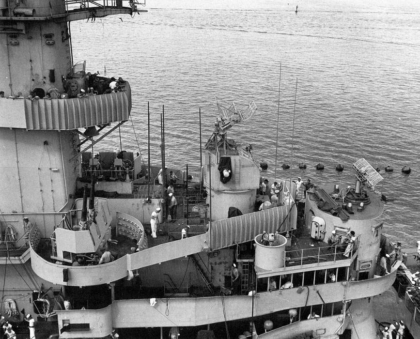
James
-
lgmccauley
- Posts: 156
- Joined: Mon Apr 13, 2015 2:16 pm
Re: Calling all USS Iowa class (BB-61) fans
Thanks for responding James.
Do you know if the halyards were tied off to the fair lead and why would some have gone directly to the flagbags? Again, I would just like to know so I know how to run the rigging.
Larry
Do you know if the halyards were tied off to the fair lead and why would some have gone directly to the flagbags? Again, I would just like to know so I know how to run the rigging.
Larry
-
James M
- Posts: 252
- Joined: Fri Apr 01, 2005 11:30 pm
- Location: Fullerton, CA
Re: Calling all USS Iowa class (BB-61) fans
The signal shelter and the flagbag lockers are two separate systems for different operations.
The halyards would have gone into the armored signal shelter and tied off inside. The fair leads just helped guide the halyards to the shelter.
They would have used the shelter for signals when the ship was in combat so as to not have the crew exposed.
That was the intended design but the ships never really got to fight as intended.
The flag bags outside where used when the ship was operating normally.
There are two flagbag lockers side by side on each side of the bridge with a complete set of flags in each and more flagbag lockers by the aft funnel.
James
The halyards would have gone into the armored signal shelter and tied off inside. The fair leads just helped guide the halyards to the shelter.
They would have used the shelter for signals when the ship was in combat so as to not have the crew exposed.
That was the intended design but the ships never really got to fight as intended.
The flag bags outside where used when the ship was operating normally.
There are two flagbag lockers side by side on each side of the bridge with a complete set of flags in each and more flagbag lockers by the aft funnel.
James
-
lgmccauley
- Posts: 156
- Joined: Mon Apr 13, 2015 2:16 pm
Re: Calling all USS Iowa class (BB-61) fans
That's exactly what I needed to know. Thanks a lot James.
Larry
Larry
-
ouizel
- Posts: 1
- Joined: Fri Aug 14, 2009 1:44 pm
Re: Calling all USS Iowa class (BB-61) fans
I'm planning a build of the old Tamiya 1:350 WWII Missouri kit. I would like to add one of the available wood veneer decks and am looking for opinions on the Pontos set v. the ArtWox set. Whichever I eventually go with I will be using the deck blue version.
Does anyone have experience with either and can give informed opinions?
Thanks!
Does anyone have experience with either and can give informed opinions?
Thanks!
-
Aur

- Posts: 140
- Joined: Thu Dec 10, 2015 10:36 pm
- Location: Bangkok, Thailand
Re: Calling all USS Iowa class (BB-61) fans

I've been searching for Iowa-class propeller profiles that would show the cap's tapered shape, but couldn't find any. So I'd be very appreciated if someone here could provide me a copy of the screw section from any accurate profile plans.
Thanks in advance,
Aur
On the way:
1/350 Tamiya DKM Tirpitz Nov 1944
1/350 scratch-build HMS Lion never built battleship (1938)
Completed build:
1/350 AFV Club Japanese Submarine I-58
And our artworks!
1/350 Tamiya DKM Tirpitz Nov 1944
1/350 scratch-build HMS Lion never built battleship (1938)
Completed build:
1/350 AFV Club Japanese Submarine I-58
And our artworks!
-
lgmccauley
- Posts: 156
- Joined: Mon Apr 13, 2015 2:16 pm
Calling all Iowa fans
I have another question in regards to Missouri's flag halyards. This time it's where the aft flag halyards were tied off. The one source I have is the 3D book on the Missouri which shows them tied off to deck mounted eyebolts located along the railings on either side of the aft flag bag. I also have the FDD plan book and the photo set of the Gibbs & Cox model. The FDD plan book and plans show the aft flag bag, but there is no definitive location of the halyards termination point. The photo set shows no aft flagbag at all and the halyards seeming to be tied off to the adjacent railings. I'm trying to determine what is correct, so any help would be appreciated.
Thanks.
Larry
Thanks.
Larry
-
chuck

- Posts: 3384
- Joined: Mon Jan 10, 2005 1:21 pm
- Location: equidistant to everywhere
Re: Calling all USS Iowa class (BB-61) fans
Is there any aftermarket rear hull correction for trumpeter's 1/200 Iowa class models?
Assessing the impact of new area rug under modeling table.
-
Timmy C
- Posts: 12473
- Joined: Mon Jan 10, 2005 6:00 pm
- Location: Ottawa, Canada
Re: Calling all Iowa fans
Mostly railings for the Iowa, if that helps: http://navsource.org/archives/01/061/016101c.jpg Flag bags under canvas covers, it seems.lgmccauley wrote:I have another question in regards to Missouri's flag halyards. This time it's where the aft flag halyards were tied off. The one source I have is the 3D book on the Missouri which shows them tied off to deck mounted eyebolts located along the railings on either side of the aft flag bag. I also have the FDD plan book and the photo set of the Gibbs & Cox model. The FDD plan book and plans show the aft flag bag, but there is no definitive location of the halyards termination point. The photo set shows no aft flagbag at all and the halyards seeming to be tied off to the adjacent railings. I'm trying to determine what is correct, so any help would be appreciated.
Thanks.
Larry
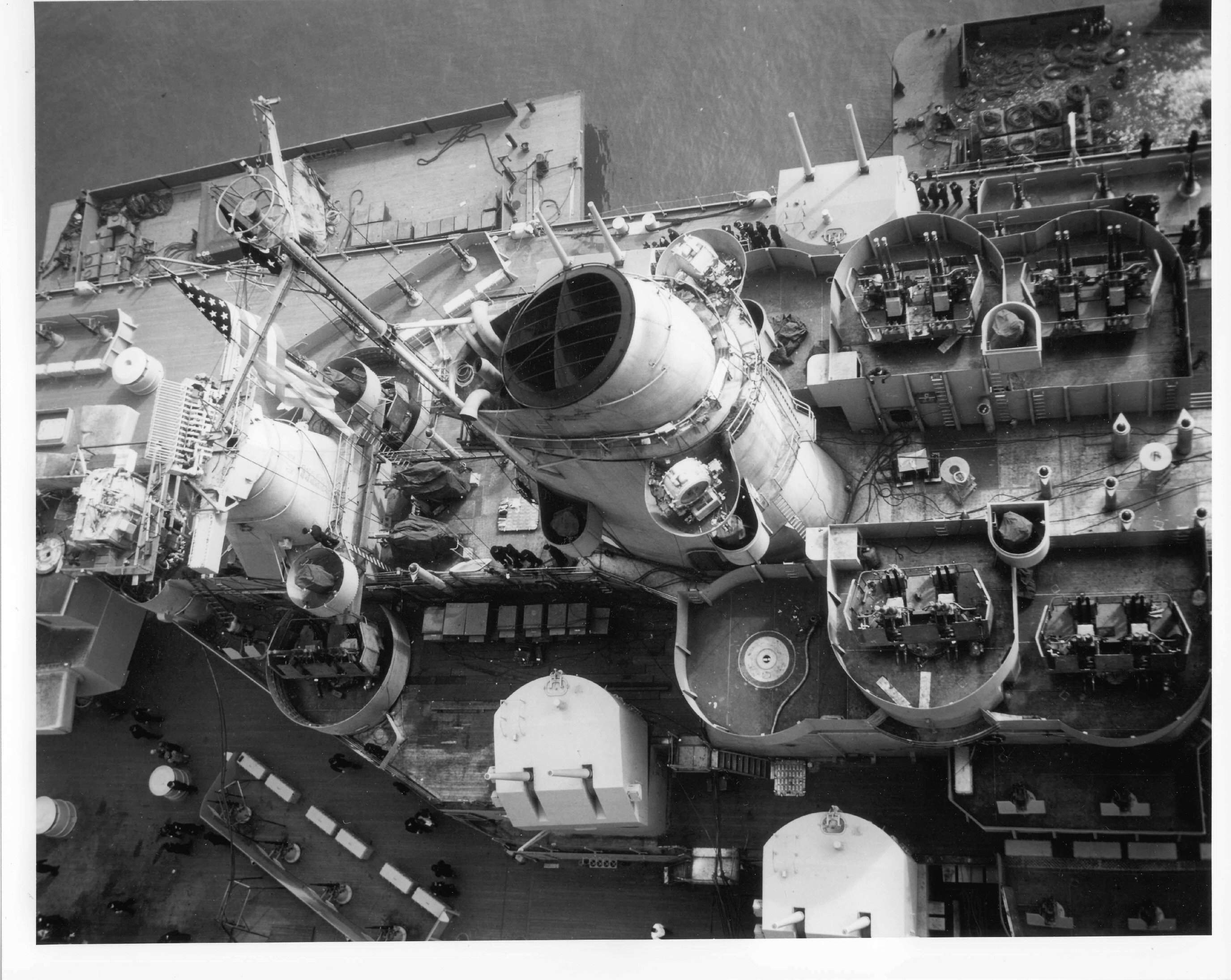
De quoi s'agit-il?
-
BB62vet
- Posts: 3163
- Joined: Mon Nov 18, 2013 3:41 pm
- Location: Mocksville, NC
Re: Calling all USS Iowa class (BB-61) fans
Chuck wrote: 
Hope this helps (I know it doesn't),
The answer is "no". You'll have to tackle this like all the rest of us - yourself!!Is there any aftermarket rear hull correction for trumpeter's 1/200 Iowa class models?
Hope this helps (I know it doesn't),
HMS III
Mocksville, NC
BB62 vet 68-69
Builder's yard:
USS STODDARD (DD-566) 66-68 1:144, Various Lg Scale FC Directors
Finished:
USS NEW JERSEY (BB-62) 67-69 1:200
USN Sloop/Ship PEACOCK (1813) 1:48
ROYAL CAROLINE (1748) 1:47
AVS (1768) 1:48
Mocksville, NC
BB62 vet 68-69
Builder's yard:
USS STODDARD (DD-566) 66-68 1:144, Various Lg Scale FC Directors
Finished:
USS NEW JERSEY (BB-62) 67-69 1:200
USN Sloop/Ship PEACOCK (1813) 1:48
ROYAL CAROLINE (1748) 1:47
AVS (1768) 1:48