Calling all USS Boston CAG-1 fans!
Moderators: MartinJQuinn, Timmy C, Gernot, Olaf Held, Dan K, HMAS, ModelMonkey
-
rtwpsom2

- Posts: 1438
- Joined: Tue Aug 19, 2008 10:15 pm
- Location: State of Denial
Re: Calling all CAG-1 USS Boston Fans!
To keep the shells from flying back into the scuttles on the front of the superstructure?
-
s4usea

- Posts: 210
- Joined: Mon Dec 05, 2011 5:47 pm
- Location: Washington, DC
Re: more progress
I showed this pic to my father who was on Boston from '66 - '68 and would go on to be gunnery officer on Barry afterwards...RandyM wrote:
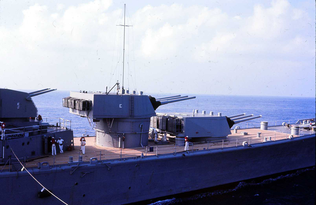
One (of many) thing I've not been able to figure out yet - the forward 5" mount on Boston had what I believe are shell ejection chutes on the back of the turret (you can just see one of them in the last image above, and clearly see them on the prototype in the image below), while the other four mounts did not. Why?
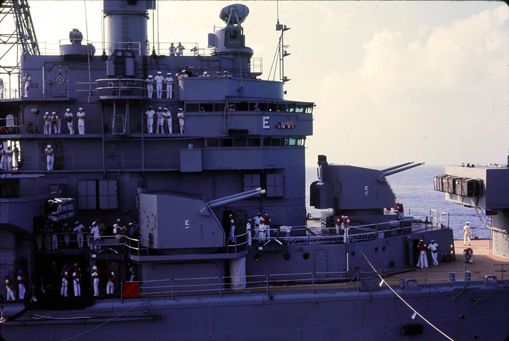
He says it's so they could retrieve the brass. Without it it would pitch the shells over the side.
Looking at the pic it makes sense as the other 5" wouldn't have this problem in firing position, but the forward one would if pointed port or starboard...
-
rtwpsom2
- Posts: 1438
- Joined: Tue Aug 19, 2008 10:15 pm
- Location: State of Denial
Re: Calling all CAG-1 USS Boston Fans!
Ah, they are not chutes, they are bins. Closed on the bottom.
-
RandyM
- Posts: 337
- Joined: Sat Dec 15, 2007 10:40 pm
- Location: San Diego
Re: Calling all CAG-1 USS Boston Fans!
Awesome - thanks for taking the time to clear this up: it does make sense.
Please thank your father for his service!
Please thank your father for his service!
-
Cliffy B

- Posts: 3125
- Joined: Sun Feb 01, 2009 3:55 pm
- Location: Hawaii
- Contact:
Re: Calling all CAG-1 USS Boston Fans!
You sure about that? They look like they'd probably jam/fill up fairly fast if they were closed.rtwpsom2 wrote:Ah, they are not chutes, they are bins. Closed on the bottom.
Drawing Board:
1/700 Whiff USS Leyte and escorts 1984
1/700 Whiff USN Modernized CAs 1984
1/700 Whiff ASW Showdown - FFs vs SSGN 1984
Slipway:
1/700 Whiff USN ASW Hunter Killer Group Dio 1984
1/700 Whiff USS Leyte and escorts 1984
1/700 Whiff USN Modernized CAs 1984
1/700 Whiff ASW Showdown - FFs vs SSGN 1984
Slipway:
1/700 Whiff USN ASW Hunter Killer Group Dio 1984
-
rtwpsom2
- Posts: 1438
- Joined: Tue Aug 19, 2008 10:15 pm
- Location: State of Denial
Re: Calling all CAG-1 USS Boston Fans!
No, not sure at all.
-
s4usea
- Posts: 210
- Joined: Mon Dec 05, 2011 5:47 pm
- Location: Washington, DC
Re: Calling all CAG-1 USS Boston Fans!
No. they weren't. They defected the shells down rather than out. Another thing he pointed out is on his midshipman cruise aboard Newport News the forward 5" didn't have them and the shells would tear up the teak deck and bounce off of it...rtwpsom2 wrote:No, not sure at all.
-
DrPR

- Posts: 1689
- Joined: Sun Mar 07, 2010 12:01 am
- Location: Corvallis, Oregon, USA
- Contact:
Re: Calling all CAG-1 USS Boston Fans!
It may sound funny at first that they worried about shell casings going over the side in combat. But during Vietnam we were supposed to be frugal. We might be pumping hundreds of rounds ($$$) into the jungle during "harrassment and interdiction" (H&I) fire that had no targets, but we were supposed to save the powder cases for recycling.
On the Oklahoma City we laid out plywood sheets on the deck before fire missions to protect the Admiral's teak decks. After a mission the crew gathered up the shell casings, put them back into the powder shipping containers, and returned them to the magazine. On the next ammunition UNREP we sent the empty cases back.
Or at least most of them. Quite a few were "lost over the side" and became souvenier ash trays. And when we went into Hong Kong we traded shell casings for a paint job on the hull. Comshaw is the term for it. Can't remember now the woman's name who ran that business, but she would bring a bunch of sampans out and do the work in exchange for brass. They didn't use brushes for the detail work but just smeared on the paint with their hands.
Phil
A collision at sea will ruin your entire day. Aristotle
-
RandyM
- Posts: 337
- Joined: Sat Dec 15, 2007 10:40 pm
- Location: San Diego
more progress
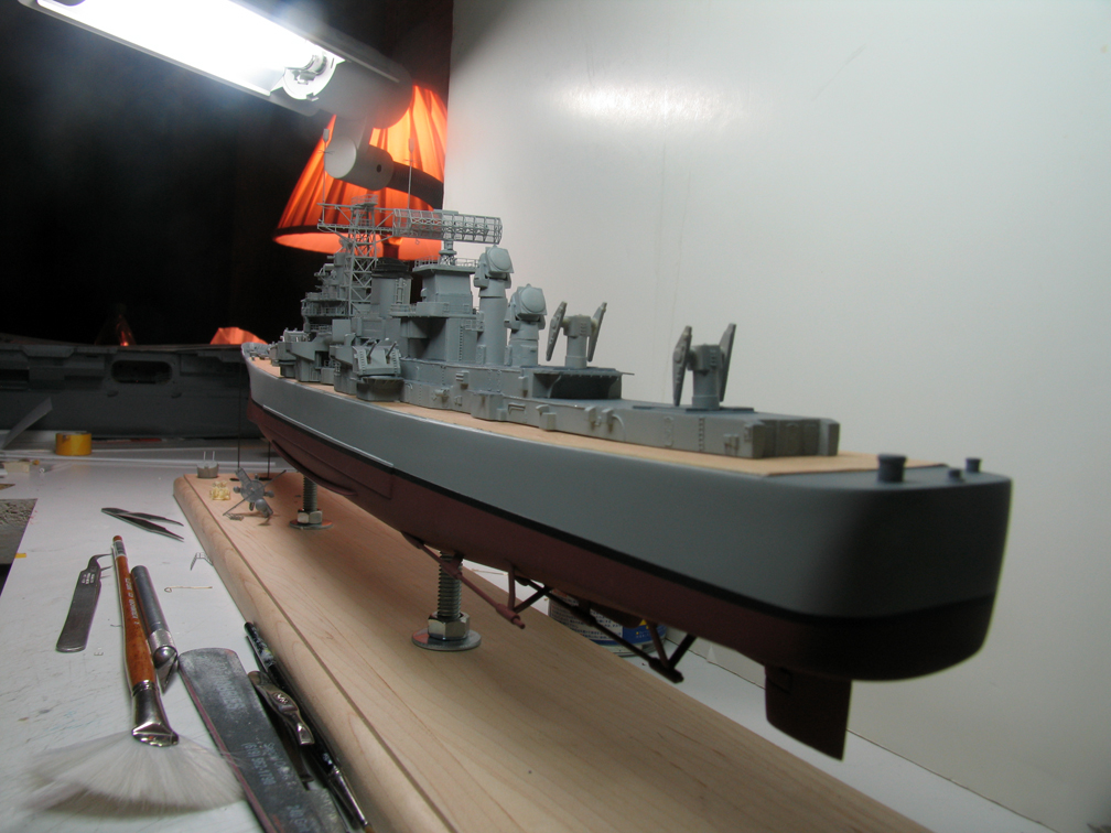
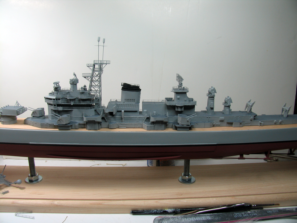
Spent this weekend's effort mainly building the SQ-5 radar sets. I wound up using the mounts from the kit, but scratchbuilt the transmitters. Also painted the tops of the 8" and 5" turrets, the main tower and the SPS-43 radar antenna (all of which are posing for pics). Added some more railing amidships.
DaveP - I don't yet understand your question re: turret 2... please clarify since if you see something really wrong, I want to fix it!
Another question I have: if you look at the base of the tower (middle photo) you will see a structure "embedded" within the tower - it is two levels in height on the 03 and 04 levels. It almost looks like an elevator. Does anyone know in fact what it is?
-
Dick J

- Posts: 1991
- Joined: Mon Aug 06, 2007 6:29 pm
Re: more progress
A little quick history: When the Wichita was designed, she was intended to have the turrets of the later New Orleans class. But the barrel spacing created a dispersion problem when the guns were fired together. To correct it, the turret was redesigned to allow enough spacing for independent elevation, and therefore independent loading and firing. But to keep the weight within limits, the bases of the barbettes were kept the original diameter, while the upper ends were widened to fit the larger turrets. The added topweight is why Wichita always had stability issues. The Baltimore design was started as an attempt to modify the Wichita design to regain adequate stability. The Wichita turrets were carried over into the Baltimore design, complete with the conical barbettes. The taper was only visible on the turret II barbette, but is really mostly noticed by those specifically looking for it.RandyM wrote:DaveP - I don't yet understand your question re: turret 2... please clarify since if you see something really wrong, I want to fix it!
-
RandyM
- Posts: 337
- Joined: Sat Dec 15, 2007 10:40 pm
- Location: San Diego
Re: Calling all CAG-1 USS Boston Fans!
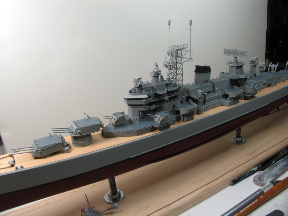
Ahhh - interesting - thanks for the info: now I understand Dave's question, and it explains the photo below. I puzzled over this for some time: the forward edge of the #2 barbette is clearly angled outward/up, yet the rear edge appears to be vertical with respect to the maindeck, almost as if the conical shape is non-uniform around the circumference. Armed with your description and looking at the photo, it is probably the presence of the ladder at the after edge that is obscruing the angle of that edge and creating an optical illusion (that the rear edge is vertical). I couldn't figure how to create that sort of shape, so I basically punted. And it does look like after cleaning the kit part up I put it on upside down. Since it is glued to a real-wood deck, I'm not sure I'm ready to perform a barbette-ectomy. We'll see... 
-
RandyM
- Posts: 337
- Joined: Sat Dec 15, 2007 10:40 pm
- Location: San Diego
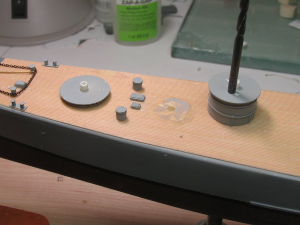
Success!
After verifying that I had installed the barbette upside down (doh! THANK YOU DaveP and DickJ for helping me see the error of my ways), I mulled over how/whether to deal with it all day at work - which meant work suffered a bit.
So..... a controlled application of dental floss and leverage solved the problem of non-destructive removal: now the rest is easy. And this goes to show just how tough these ScaleDecks decks really are - the barbette was s*t*u*c*k.
Does anyone have accurate, dimensioned drawings showing the shape/taper of the barbette?
-
rtwpsom2
- Posts: 1438
- Joined: Tue Aug 19, 2008 10:15 pm
- Location: State of Denial
Re: Calling all CAG-1 USS Boston Fans!
Randy, they were 24' across at the top with a 4 degree inward slope.
-
Dick J
- Posts: 1991
- Joined: Mon Aug 06, 2007 6:29 pm
Re: Calling all CAG-1 USS Boston Fans!
I'm glad you were able to remove it relatively easily. Even though most who would look at the model wouldn't notice the barbette, YOU would know - and it would have gnawed on you forever!  At least, now that it will be fixed, you can sleep at night - and pay closer attention to the job while at work.
-
RandyM
- Posts: 337
- Joined: Sat Dec 15, 2007 10:40 pm
- Location: San Diego
ARRRRGGGGGHHHHH!!!! Thanks a LOT you guys...
I'm currently on Turret 2 Barbette v3.0. The first one - as was (thankfully) pointed out to me - was installed by yours truly upside down. I put this down to lack of research, a good dose of stupidity, and possibly the fact that I am not a "ship builder" (I build pretty much anything). I seriously had no clue that a barbette would be designed to get wider at the mount vs. the deck. Having looked into it further, the reasons given make sense.
Anyway, here we are. v1.0 was upside down, and I removed it as mentioned earlier. I also received some good info regarding the dimensions of the barbette, and it turns out the YMW part is THREE scale feet smaller in diameter. If this was a length issue I might not have cared, but since it is a diameter, that equates to a much less-massive appearance. So I set about constructing v2.0 built up from sheet styrene. I got the piece nicely done and detailed - it looked the right shape, etc. I painted it and set it in place on the deck of Boston, and it took about 3 microseconds for me to realize I had committed yet another "d'oh!"
In this case, I had made the bottom face of the barbette parallel to the top face, and when placed on the sloping foredeck, it was clearly incorrect. I flashed back to my days in USCG aboard a WHEC (pre-FRAM) and recalled how the 5" mount always looked "funny" when standing on deck next to it - because the top of the turret was parallel to the WATER, not the DECK.
No big deal, right? I'll just sand the bottom face until I arrive at the correct attitude for the barbette. So I took some measurements, made some marks, and started merrily sanding away... right through the 0.010" bottom face of the v2.0 framework. Arrrggghhh.
At this point, I'm halfway through construction of v3.0. This time I started with the original YMW part (after stripping it of a day's worth of detail), sanded it to the correct conical shape AND adjusted the angle of the bottom face, then laminated a series of 0.015" sheet layers to build up to the appropriate diameter(s). So far so good.
-
RandyM
- Posts: 337
- Joined: Sat Dec 15, 2007 10:40 pm
- Location: San Diego
first looks...
Ok, despite all my prior whining, here is the v3.0 barbette. It is just posing for now, so if you see something that you think is a "first order" issue, please let me know. Note that the lower-left ladder is a bit "bent" - the bottom of this part gets connected directly to the deck, so I'll straighten it out once I mount the barbette. For the LAST time.
Comparing it to the v1.0 photos, it looks MUCH closer to the prototype. All kidding aside - thanks to everyone who help straighten (?) this out.
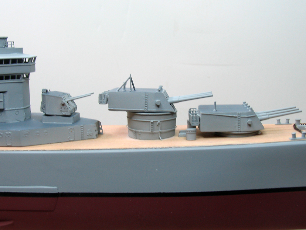
Comparing it to the v1.0 photos, it looks MUCH closer to the prototype. All kidding aside - thanks to everyone who help straighten (?) this out.
-
Dick J
- Posts: 1991
- Joined: Mon Aug 06, 2007 6:29 pm
Re: Calling all CAG-1 USS Boston Fans!
Looks good!! I think that your recent observation also answers one of your earlier questions on the taper in the photo of the actual ship. The apparent angle between the vertical side of the barbette and the deck - it looked almost vertical on the back side. Because the deck slopes, the angle between the back side of the barbette and the deck should be closer to square than the forward one. The ladder is not the only optical effect at work there. After all, the effect even shows on the photo you just posted.
-
gtbred

- Posts: 2717
- Joined: Wed Jan 13, 2010 9:10 am
- Location: san francisco
Re: Calling all CAG-1 USS Boston Fans!
she looks good Randy. 
-
RandyM
- Posts: 337
- Joined: Sat Dec 15, 2007 10:40 pm
- Location: San Diego
Update - nothing really to report
It's been weeks since I last checked in, and just wanted to let y'all know that a) yes I am still alive, and b) I've not made much progress. Work has been.... well, WORK of late. No complaints here but I've been pretty much consumed between that and summertime honey-doo lists around the house. Pretty much the only thing I've managed on Boston is a bit of progress on the two cranes. And I've got to tell you, here is an area in which the engineering of this kit really lags. You're supposed to build up both cranes, but they are supposed to mount through holes in the flagbag deck. So.... how do you mount a fully-assembled and rigged crane into a hole in a deck????
Photos later - just take my word for it for now
Photos later - just take my word for it for now
-
Seasick

- Posts: 1550
- Joined: Thu Sep 22, 2005 8:58 pm
- Location: Houston, Texas
Re: Calling all CAG-1 USS Boston Fans!
The Canberra CAG-2 had AN/SPQ-5 radars for Terrier, the Boston never had them fit. The Boston had the Mk 25 mod 7 radars instead.
???????
? Seasick?
???????
? Seasick?
???????