At 'Em Arizona Fans!
Moderators: BB62vet, MartinJQuinn, Timmy C, Gernot, Olaf Held, Dan K, HMAS, ModelMonkey
-
BFR4570
- Posts: 403
- Joined: Sun Jul 25, 2010 5:13 am
- Location: Tucson, Arizona
Re: At 'Em Arizona Fans!
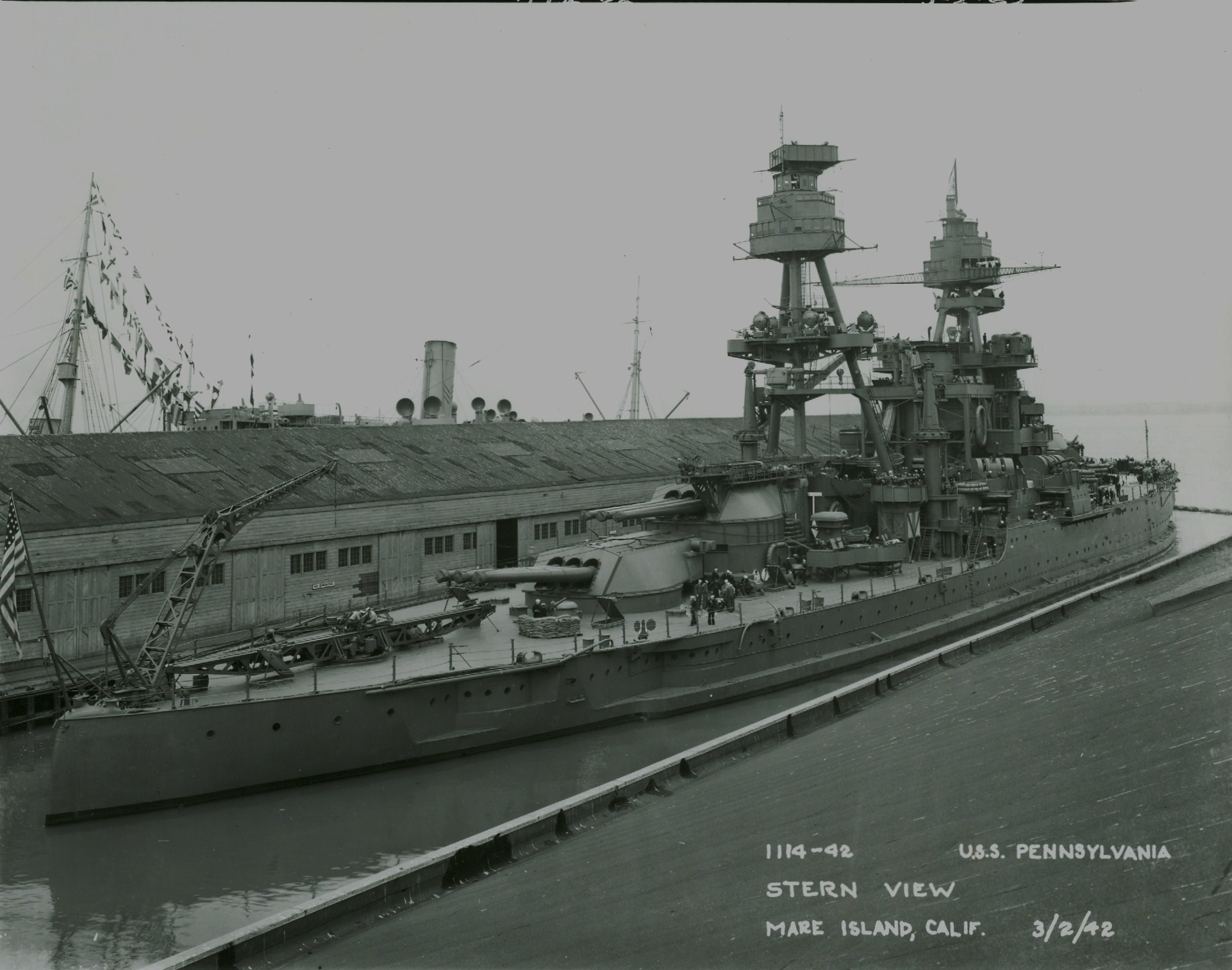
How about pics of the Pennsy, or the other Super Dreadnaughts? I just checked USN Battleships In Color. There are a couple of pics showing boats tied up in the area of these cleats, but I could not see the cleats themselves. Could the front of the boats be tied to the boom, while a second line went to the cleat to keep the boat parallel to the ship?
-
Tracy White
- Posts: 10628
- Joined: Mon Jan 10, 2005 11:02 am
- Location: EG48
- Contact:
Re: At 'Em Arizona Fans!
No need for a second line; the boats are subject to the same currents and winds as the ship and will ride the bow line to the boom at the same angle.
Tracy White -Researcher@Large
"Let the evidence guide the research. Do not have a preconceived agenda which will only distort the result."
-Barbara Tuchman
"Let the evidence guide the research. Do not have a preconceived agenda which will only distort the result."
-Barbara Tuchman
-
BFR4570
- Posts: 403
- Joined: Sun Jul 25, 2010 5:13 am
- Location: Tucson, Arizona
Re: At 'Em Arizona Fans!
Steve, Can you post these pics on the Main forum? Maybe someone out there who doesn't follow the Arizona may know what they are for.
-
Steve Sobieralski
- Posts: 186
- Joined: Thu Oct 27, 2005 11:52 am
- Location: Tampa, Florida, USA
-
BFR4570
- Posts: 403
- Joined: Sun Jul 25, 2010 5:13 am
- Location: Tucson, Arizona
Re: At 'Em Arizona Fans!
Is there anything else visible in these pics showing the pipe on the port side that would indicate the photo was not reversed? Such as any fitting that is only located on the port side? Or a Practice Loading Machine (was it on the port side?)? Or the Incinerator? Or the Movie Projection Booth? If any of these are visible then the drawing is obviously wrong for the Arizona. As for the pipe being routed differently on the two ships, I would presume each ship's Chief Engineer would have been in charge, or heavily involved in it. After all, they are messing with his ship! Has anyone ever heard of any two engineers who will route a pipe in exactly the same way? That may be why they were on opposite sides of the ship. Different Engineers with different reasons. And Chesney may have been working from a set of Pennsylvania plans. Or it was intended to be put on the Starboard side of the Arizona, but Engineering had a better idea. Who knows after all these years. But at least the photos may be confirmed whether they might have been reversed or not. I have GOT to find my book!!Sten Ekedahl wrote:Another thing worth noting is that the aviation fuel pipe running along the side of the hull from the bow to the stern, is fitted on the starboard side on Pensy, but on the port side on Arizona. BTW, that is one of the few errors I have found on the drawings in Stillwell's book. The side view drawing shows the fuel pipe on the starboard side, but several photos in the book clearly shows it on the port side. There are also slight differences between the two ships regarding the routing of the pipe.
 But I am supposed to stay off my feet!
-
SeanF
- Posts: 799
- Joined: Wed Nov 02, 2005 10:28 pm
- Location: Downey, California
Re: At 'Em Arizona Fans!
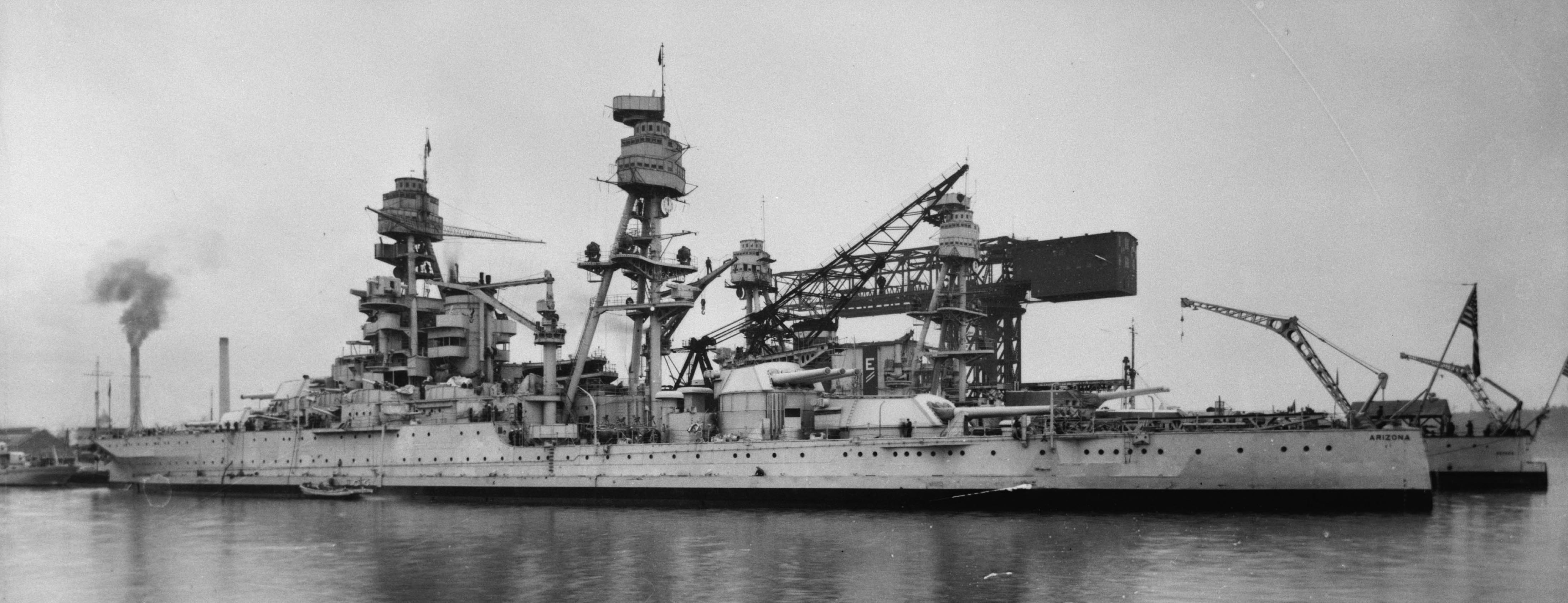
In the photo of Arizona in Jan. 1941, this ship's name can be read properly, confirming it is not a reversed picture, and the pipeline is on the port side. See: http://www.navsource.org/archives/01/013921a.jpg
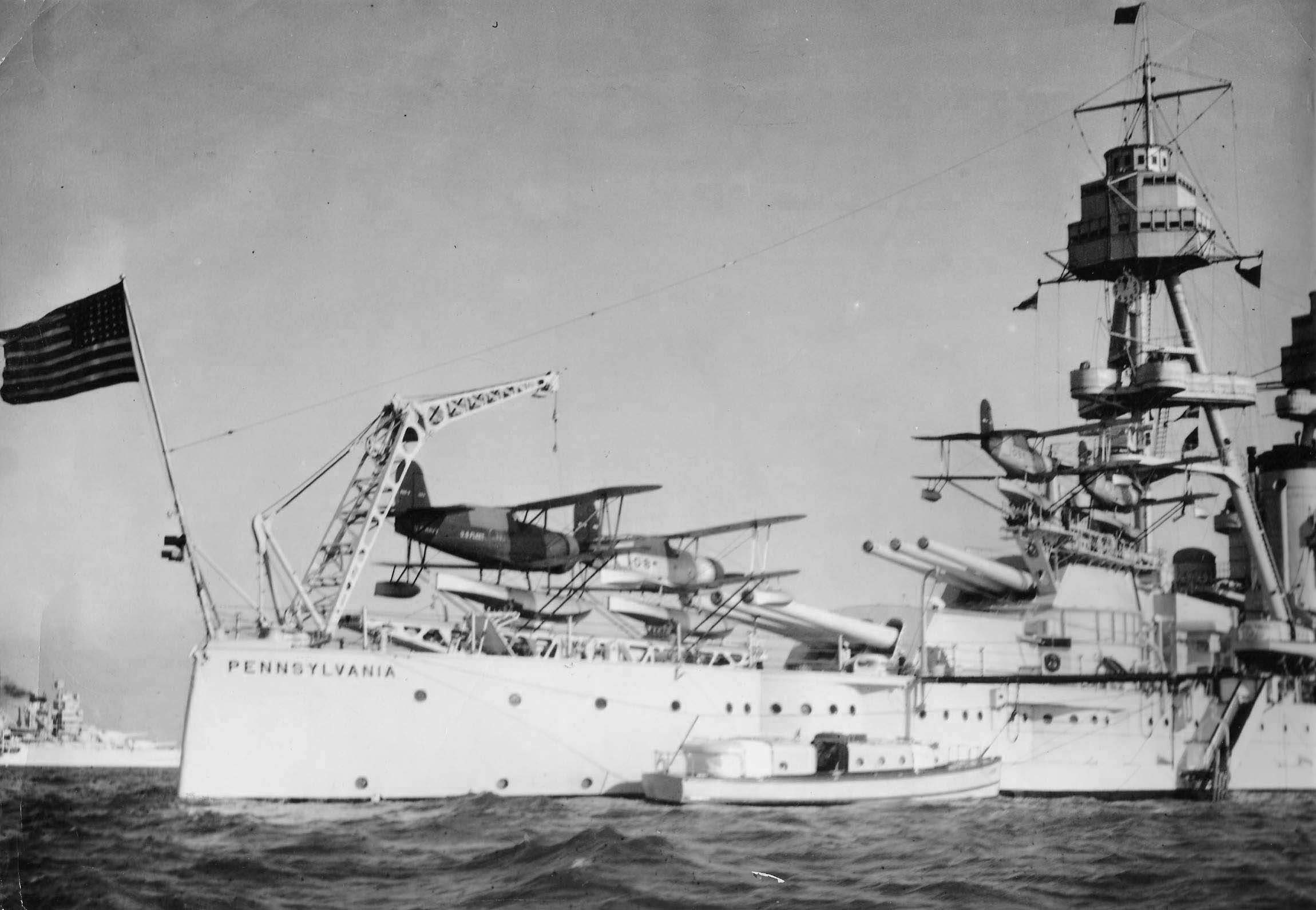
In this photo of the Pennsylvania, you can still read the name correctly and see that the pipeline is on the starboard side:
http://www.navsource.org/archives/01/013853.jpg
Other photos reveal that one side of each ship did not have a pipeline. Therefore, based on photos that can be verified as not reversed: Arizona had it on the port, and Pennsylvania on the starboard.
- Sean F.
In this photo of the Pennsylvania, you can still read the name correctly and see that the pipeline is on the starboard side:
http://www.navsource.org/archives/01/013853.jpg
Other photos reveal that one side of each ship did not have a pipeline. Therefore, based on photos that can be verified as not reversed: Arizona had it on the port, and Pennsylvania on the starboard.
- Sean F.
-
Tracy White
- Posts: 10628
- Joined: Mon Jan 10, 2005 11:02 am
- Location: EG48
- Contact:
Re: At 'Em Arizona Fans!
Not really. Generally the orders were issued from BuShips; sometimes with plans from another shipyard, if they had done the same work in the past, or based on a ShipAlt (pre-defined ship alteration). If it had not been done before plans were drawn up by the shipyard since they had more detailed plans of the ship and the people who were going to be doing the actual shipyard work. Ship's force might have been involved once the actual work was progressing, but you want the plans and material set in place BEFORE the ship arrives at the yard.BFR4570 wrote:I would presume each ship's Chief Engineer would have been in charge, or heavily involved in it. After all, they are messing with his ship!
Tracy White -Researcher@Large
"Let the evidence guide the research. Do not have a preconceived agenda which will only distort the result."
-Barbara Tuchman
"Let the evidence guide the research. Do not have a preconceived agenda which will only distort the result."
-Barbara Tuchman
-
BFR4570
- Posts: 403
- Joined: Sun Jul 25, 2010 5:13 am
- Location: Tucson, Arizona
Re: At 'Em Arizona Fans!
So someday, some order may come to light, from some archive, that might explain why the Pennsylvania had it on the starboard side, while the Arizona had it on the port side. Or they were done in different yards and each Yard Engineer decided it should be done his way due to the materials on hand, or whatever. Well, we will probably never know why. Now, if someone can come up with a aftermarket kit of this pipe that can be put on either side, so either ship can be built..... 
-
Steve Sobieralski
- Posts: 186
- Joined: Thu Oct 27, 2005 11:52 am
- Location: Tampa, Florida, USA
Re: At 'Em Arizona Fans!
I think the pipe may have been installed as part of the major refit at Norfolk in 1929-1931. I have not been able to find it on any pre-refit photos.
Steve Sobieralski
Tampa Bay Ship Model Society
Tampa Bay Ship Model Society
-
Tracy White
- Posts: 10628
- Joined: Mon Jan 10, 2005 11:02 am
- Location: EG48
- Contact:
Re: At 'Em Arizona Fans!
Is it that difficult to scratch build?BFR4570 wrote: Now, if someone can come up with a aftermarket kit of this pipe that can be put on either side, so either ship can be built.....
Tracy White -Researcher@Large
"Let the evidence guide the research. Do not have a preconceived agenda which will only distort the result."
-Barbara Tuchman
"Let the evidence guide the research. Do not have a preconceived agenda which will only distort the result."
-Barbara Tuchman
-
BFR4570
- Posts: 403
- Joined: Sun Jul 25, 2010 5:13 am
- Location: Tucson, Arizona
Re: At 'Em Arizona Fans!
Don't know! Haven't tried it yet!Tracy White wrote:Is it that difficult to scratch build?BFR4570 wrote: Now, if someone can come up with a aftermarket kit of this pipe that can be put on either side, so either ship can be built.....
 Since Trumpy left it off, this will be a good place to try it.
-
Tracy White
- Posts: 10628
- Joined: Mon Jan 10, 2005 11:02 am
- Location: EG48
- Contact:
Re: At 'Em Arizona Fans!
That's the attitude we're looking for!*
* Nothing against those who just want to assemble parts of course, but we also aim to get people past hurdles.
* Nothing against those who just want to assemble parts of course, but we also aim to get people past hurdles.
Tracy White -Researcher@Large
"Let the evidence guide the research. Do not have a preconceived agenda which will only distort the result."
-Barbara Tuchman
"Let the evidence guide the research. Do not have a preconceived agenda which will only distort the result."
-Barbara Tuchman
-
Sten Ekedahl

- Posts: 144
- Joined: Thu Aug 10, 2006 6:11 pm
- Location: Stockholm, Sweden
Re: At 'Em Arizona Fans!
A few more observations on those fuel pipes:
1. The starting point at the bow seems to be slightly further forward on Pennsylvania.
2. The pipe looks to be about 3" diameter (.02" in 1/350). Edit: Mental error! It should of course be 0.21 mm, or .008", in 1/350!
3. The first couple of feet of the pipe on the bow has some type of strengthening or protective cover. Clearly visible on the Pennsy photos as a 4-5" pipe covering the fuel pipe. A slightly different arrangement on Arizona, but difficult to figure out as the photos I have are taken from a distance.
4. The pipe ends at the stern into a angular boxlike structure, presumably containing the attachment point for the hose used to fuel the aircraft on the rear catapult. On Arizona that box is level with the rear deck, in the corner aft of the original rearmost casemate gun. On Pennsy however, that "box" is in the corresponding corner aft of the second rearmost casemate gun.
5. On both ships there is a similar hose attachment point at deck level abreast the number 3 main turret, presumably for fueling the aircraft on the turret catapult. This fueling point is served from a slightly thinner pipe (2"?) going vertically up from the main pipe.
Hope all this makes sense. Being a non native speaker, technical and nautical terms in English is not one of my strengths.
1. The starting point at the bow seems to be slightly further forward on Pennsylvania.
2. The pipe looks to be about 3" diameter (.02" in 1/350). Edit: Mental error! It should of course be 0.21 mm, or .008", in 1/350!
3. The first couple of feet of the pipe on the bow has some type of strengthening or protective cover. Clearly visible on the Pennsy photos as a 4-5" pipe covering the fuel pipe. A slightly different arrangement on Arizona, but difficult to figure out as the photos I have are taken from a distance.
4. The pipe ends at the stern into a angular boxlike structure, presumably containing the attachment point for the hose used to fuel the aircraft on the rear catapult. On Arizona that box is level with the rear deck, in the corner aft of the original rearmost casemate gun. On Pennsy however, that "box" is in the corresponding corner aft of the second rearmost casemate gun.
5. On both ships there is a similar hose attachment point at deck level abreast the number 3 main turret, presumably for fueling the aircraft on the turret catapult. This fueling point is served from a slightly thinner pipe (2"?) going vertically up from the main pipe.
Hope all this makes sense. Being a non native speaker, technical and nautical terms in English is not one of my strengths.
Last edited by Sten Ekedahl on Fri Nov 12, 2010 9:21 pm, edited 2 times in total.
Sten Ekedahl
Maj. (Retd) RSwAF
Maj. (Retd) RSwAF
-
SeanF
- Posts: 799
- Joined: Wed Nov 02, 2005 10:28 pm
- Location: Downey, California
Re: At 'Em Arizona Fans!
Your English makes very good sense, Sten. Those are exactly the things I've been noticing about the pipes on these sister ships.
Here's the url for a pretty good shot of the box at the back of the Arizona:
http://navsource.org/archives/01/039/013933w.jpg
Note that the pipeline is up near the deck at this point. On Pennsylvania, it remained lower before turning straight up into the box (I'm guessing it houses the pump, with the big holes for cooling airflow) See the url in my previous post, and this one:
http://www.navsource.org/archives/01/013865.jpg
I've been studying these closely for my 1:350 Pennsy and a friend's simultaneous 1:350 'Zona project. Gluing a 0.02 brass rod to the side is the easy part; the tough part is trying to replicate the little brackets, which I estimate to be at about 3 feet on-center on the real thing, or round-about 0.1" in 1:350 scale. I'm thinking of trying Tamiya's 1:350 photoetched degaussing cable (meant for their IJN cruisers) which has brackets at just about the right spacing; it's also a bit simplistic in its representation of a degaussing cable, which actually works in my favor here.
Here's a pretty good close-up of the pipeline on the port side of the New Mexico:
http://navsource.org/archives/01/040/014082.jpg
Looking through photos of the other US battleships of the 1930s, it looks like a nearly even split of port and starboard pipelines. Perhaps the logic was that, since combat was meant to occur off one side of the battle line at a time, that only half the ships would get their avgas lines chewed up by enemy fire, while the other half of the ships would still have functional lines since they were on the leeward side of the hull? (The planes themselves, of course, being in the air during the battle or (more likely) bombardment, doing their Observation duties)
- Sean F.
Here's the url for a pretty good shot of the box at the back of the Arizona:
http://navsource.org/archives/01/039/013933w.jpg
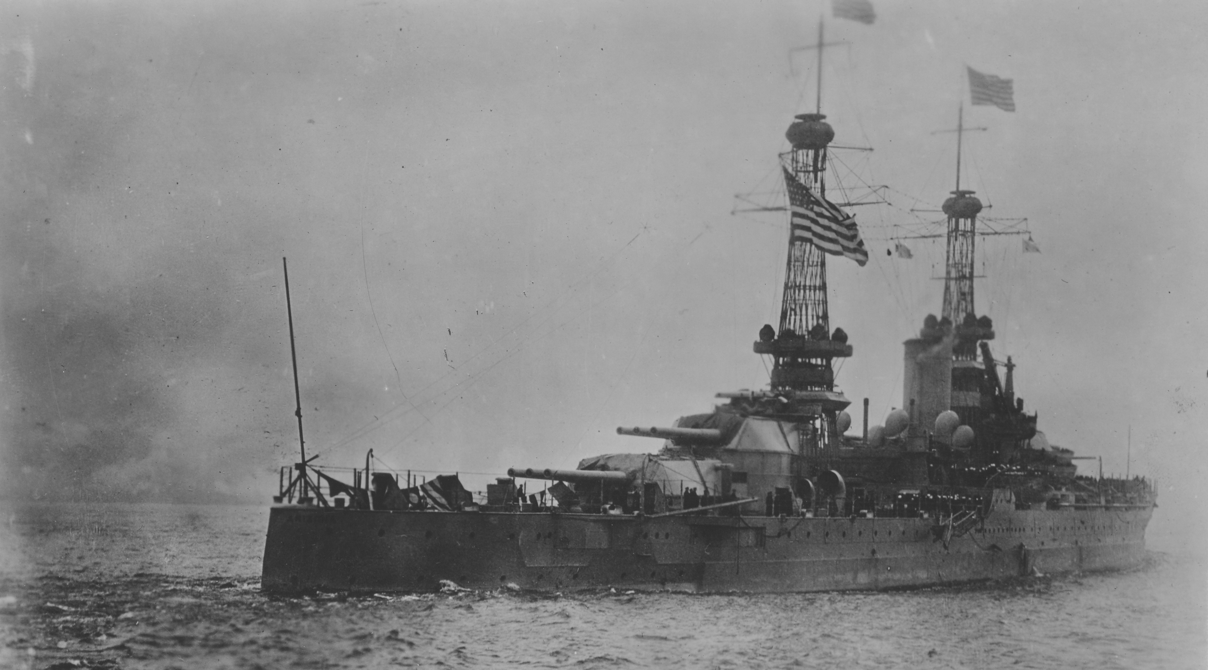
Note that the pipeline is up near the deck at this point. On Pennsylvania, it remained lower before turning straight up into the box (I'm guessing it houses the pump, with the big holes for cooling airflow) See the url in my previous post, and this one:
http://www.navsource.org/archives/01/013865.jpg
I've been studying these closely for my 1:350 Pennsy and a friend's simultaneous 1:350 'Zona project. Gluing a 0.02 brass rod to the side is the easy part; the tough part is trying to replicate the little brackets, which I estimate to be at about 3 feet on-center on the real thing, or round-about 0.1" in 1:350 scale. I'm thinking of trying Tamiya's 1:350 photoetched degaussing cable (meant for their IJN cruisers) which has brackets at just about the right spacing; it's also a bit simplistic in its representation of a degaussing cable, which actually works in my favor here.
Here's a pretty good close-up of the pipeline on the port side of the New Mexico:
http://navsource.org/archives/01/040/014082.jpg

Looking through photos of the other US battleships of the 1930s, it looks like a nearly even split of port and starboard pipelines. Perhaps the logic was that, since combat was meant to occur off one side of the battle line at a time, that only half the ships would get their avgas lines chewed up by enemy fire, while the other half of the ships would still have functional lines since they were on the leeward side of the hull? (The planes themselves, of course, being in the air during the battle or (more likely) bombardment, doing their Observation duties)
- Sean F.
-
Sten Ekedahl
- Posts: 144
- Joined: Thu Aug 10, 2006 6:11 pm
- Location: Stockholm, Sweden
Re: At 'Em Arizona Fans!
I have just corrected the embarrassing math mistake I made in my previous post. 
For my 1/350 Arizona I have decided to make this pipe from 0.3 mm (.012") plastic rod. That would be 4" in full scale. Slightly too thick if the pipe really was 3", but that is the thinnest available plastic rod at my LHS. The alternative would be to use stretched sprue, but it is extremely difficult (at least for me) to maintain a correct and constant thickness when stretching it. The fastening brackets along the length of pipe? Well the real size of these looks to me be less than an inch, which would make it virtually impossible to recreate all of them in 1/350 scale! Instead I think I'll try to create an impression of them after having painted the hull, with evenly placed tiny spots of dark paint.
For my 1/350 Arizona I have decided to make this pipe from 0.3 mm (.012") plastic rod. That would be 4" in full scale. Slightly too thick if the pipe really was 3", but that is the thinnest available plastic rod at my LHS. The alternative would be to use stretched sprue, but it is extremely difficult (at least for me) to maintain a correct and constant thickness when stretching it. The fastening brackets along the length of pipe? Well the real size of these looks to me be less than an inch, which would make it virtually impossible to recreate all of them in 1/350 scale! Instead I think I'll try to create an impression of them after having painted the hull, with evenly placed tiny spots of dark paint.
Sten Ekedahl
Maj. (Retd) RSwAF
Maj. (Retd) RSwAF
-
BFR4570
- Posts: 403
- Joined: Sun Jul 25, 2010 5:13 am
- Location: Tucson, Arizona
Re: At 'Em Arizona Fans!
Sten, does your LHS have brass rod or wire? Or maybe a hardware store might have them? Should be available in finer diameters than the plastic rod.
-
Sten Ekedahl
- Posts: 144
- Joined: Thu Aug 10, 2006 6:11 pm
- Location: Stockholm, Sweden
Re: At 'Em Arizona Fans!
Yes they have all possible sizes of both brass rods and brass tubes, and I will probbably use that for jackstaff and similar things. But for the fuelpipe I think I'd rather prefere using plastic rod.BFR4570 wrote:Sten, does your LHS have brass rod or wire? Or maybe a hardware store might have them? Should be available in finer diameters than the plastic rod.
Sten Ekedahl
Maj. (Retd) RSwAF
Maj. (Retd) RSwAF
-
Shaun Carter
Question on vertical ladders on turrets
The 1/200 Trumpeter kit has the vertical ladders on the turrets molded on both sides and I am planning on replacing them with PE. In looking at the pictures of the Pearl Harbor model I noted that they are not shown on the starboard side. So I checked the photos on navsource and could only see them on the port side of all the turrets and only on the starboard side of turret number 3. The ladder on turret 3 also seems to meet the catapult and stands away from the turret side farther than the others. Can anyone confirm?
Thanks
Shaun
Thanks
Shaun
-
BFR4570
- Posts: 403
- Joined: Sun Jul 25, 2010 5:13 am
- Location: Tucson, Arizona
Re: Question on vertical ladders on turrets
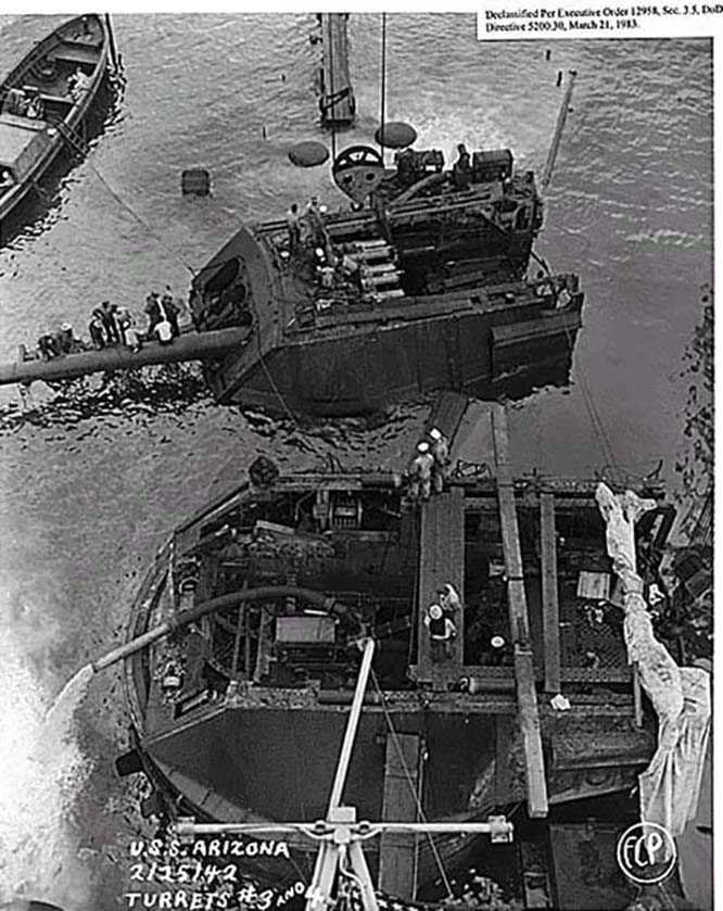
I agree. The Navsource pics that appear to show ladders seem to show them on the port side of all four turrets. One pic does seem to show a ladder on the starboard side of #3 that looks like it goes to the catapult, instead of the top of the turret. Here is an aftermath pic of the remaining ship above water. It shows a ladder on the port side of #3 & #4. It also clearly shows these turrets to be much lighter in color than I would presume 5-D to be.Shaun Carter wrote:The 1/200 Trumpeter kit has the vertical ladders on the turrets molded on both sides and I am planning on replacing them with PE. In looking at the pictures of the Pearl Harbor model I noted that they are not shown on the starboard side. So I checked the photos on navsource and could only see them on the port side of all the turrets and only on the starboard side of turret number 3. The ladder on turret 3 also seems to meet the catapult and stands away from the turret side farther than the others. Can anyone confirm?
Thanks
Shaun
http://www.navsource.org/archives/01/013916b.jpg

Here is another pic, this time showing the starboard side of both these turrets, and #4 appears to have a ladder. The ladder to the catapult appears to have been removed with said catapult from #3.
http://www.navsource.org/archives/01/013958e.jpg
There is also inconsistancies in the pics. A 1935 pic at Long Beach doesn't seem to have any ladders on the port side of the rear turrets (there may be one in the shadow on #3), and just vague shadows on the front turrets. Yet an earlier pic (listed earlier, but just said 1930s) with all main turrets trained to about ten o'clock seems to show port ladders on the rear turrets.
http://www.navsource.org/archives/01/013929a.jpg

http://www.navsource.org/archives/01/013926a.jpg

Most of the pics seem fairly consistant, except the 1935 Long Beach that seems to have no ladder on #4. But maybe at the time of her demise, she did have ladders on both sides of all the turrets. #4 sure seems to! Possibly installed in October when she was in dry-dock in Pearl? We need more pics!
-
Tracy White
- Posts: 10628
- Joined: Mon Jan 10, 2005 11:02 am
- Location: EG48
- Contact:
Re: Unboxing Arizona
*_* Nocommodore4 wrote:We,ll see. anyway ,I think the ship was MEDIUM LIGHT GREY(HAZE GREY ???) in color that morning.
She was in #5 Standard Navy Gray from 1921 or so until late May/early June, 1941. She was then painted into a two-tone Measure 1 featuring 5-L Light Gray from the top of the stacks UP and 5-D Dark Gray on every vertical surface DOWN from that point. In October of that year she was involved in a collision and went in for drydock work; she MAY have been painted in the regular Measure 1 again, or she MAY have been painted in a modified Measure 1 that replaced the 5-D Dark Gray with 5-S Sea Blue. She may have also been painted in accordance with "Modified Measure 2" that called for painting 5-O Ocean Gray as needed when repainting areas above the main deck. We do not have any proof either way.
All of these paints pre-date the FS system so there are no FS equivalents. Plenty of sites willing to tell you what they think they are though.
Tracy White -Researcher@Large
"Let the evidence guide the research. Do not have a preconceived agenda which will only distort the result."
-Barbara Tuchman
"Let the evidence guide the research. Do not have a preconceived agenda which will only distort the result."
-Barbara Tuchman