If you happen to be using the WEM P/E set for the HORNET, these platforms are included. Not sure about any other sets.
If one looks at the second photo above of HORNET in the drydock, one can see the block and tackle used to pull the platform up to the vertical. My guess would be that the platform is hinged to the focs'l deck and would remain there in the up position at all times. If someone knows that it is detached or laid flat on the deck when not entering port, please let me know. I'm close to attaching mine in the up position assuming that is how it is stowed underway. While there is no doubt the fine (very narrow) bow plunges in heavy seas, it would seem that the large amount of flare around the bow would push the seas away from the focs'l deck (at least a large part of them as seen in the photo immediately above where the seas are being pushed forward and away from the ship as the flare does its work) so that such a small structure might not be at risk even in heavy seas. I'm no naval architect, but I'm pretty sure that's why the bow is shaped as it is with so much flare. In order to get the speed into the hull, the bow is a very long and narrow wedge which results in very limited buoyancy forward. OBTW, the same issue is true for the IOWA class which instead added a large amount of shear to the forward main deck along with much less flare to reduce how much of the bow is buried in heavy seas. Notice that the IOWAS have a large deflector forward of the number one turret to force water away from the turret base. That the YORKTOWNs have no similar deflector on the focs'l deck suggests to me that perhaps they were not as concerned with water over the bow. I'm sure some came up the hawse pipes, though. I'd bet the YORKTOWN designers wanted / needed a flat focs'l deck so shearing it was not an option - hence the large amount of flare.
But I digress . . .
Still, this is why I got so bugged (see approx page ten this thread) about the correct hull shape for the model. There are sound engineering reasons for why the hull looks as it does.
Calling all USS Hornet CV-8 fans
Moderators: BB62vet, MartinJQuinn, Timmy C, Gernot, Olaf Held, Dan K, HMAS, ModelMonkey
-
John W.

- Posts: 518
- Joined: Tue Mar 27, 2007 12:34 pm
- Location: Smithfield, Virginia
Re: Calling all USS Hornet CV-8 fans
Some people make you happy, then they leave.
Others make you happy when they leave. (apologies to Oscar Wilde if he ever said anything similar, of which there is some doubt . . .)
Others make you happy when they leave. (apologies to Oscar Wilde if he ever said anything similar, of which there is some doubt . . .)
-
Michael Vorrasi

- Posts: 476
- Joined: Sun May 08, 2005 11:15 am
- Location: Brooklyn NY USA
Re: Calling all USS Hornet CV-8 fans
John, Not up, clearly. I'd go with flat on the deck. I have another shot somewhere that shows this from a better angle and the platforms are not visible, so I think they were folded over onto the deck, maybe hinged, so the bottom side faced up. Either that, or they were just lifted away and stowed elsewhere to avoid a tripping hazard on the deck. I'll keep looking for better a shot, but I would not put them up in any event.John W. wrote:If you happen to be using the WEM P/E set for the HORNET, these platforms are included. Not sure about any other sets.
If one looks at the second photo above of HORNET in the drydock, one can see the block and tackle used to pull the platform up to the vertical. My guess would be that the platform is hinged to the focs'l deck and would remain there in the up position at all times. If someone knows that it is detached or laid flat on the deck when not entering port, please let me know. I'm close to attaching mine in the up position assuming that is how it is stowed underway. While there is no doubt the fine (very narrow) bow plunges in heavy seas, it would seem that the large amount of flare around the bow would push the seas away from the focs'l deck (at least a large part of them as seen in the photo immediately above where the seas are being pushed forward and away from the ship as the flare does its work) so that such a small structure might not be at risk even in heavy seas. I'm no naval architect, but I'm pretty sure that's why the bow is shaped as it is with so much flare. In order to get the speed into the hull, the bow is a very long and narrow wedge which results in very limited buoyancy forward. OBTW, the same issue is true for the IOWA class which instead added a large amount of shear to the forward main deck along with much less flare to reduce how much of the bow is buried in heavy seas. Notice that the IOWAS have a large deflector forward of the number one turret to force water away from the turret base. That the YORKTOWNs have no similar deflector on the focs'l deck suggests to me that perhaps they were not as concerned with water over the bow. I'm sure some came up the hawse pipes, though. I'd bet the YORKTOWN designers wanted / needed a flat focs'l deck so shearing it was not an option - hence the large amount of flare.
But I digress . . .
Still, this is why I got so bugged (see approx page ten this thread) about the correct hull shape for the model. There are sound engineering reasons for why the hull looks as it does.
Mike

-
John W.
- Posts: 518
- Joined: Tue Mar 27, 2007 12:34 pm
- Location: Smithfield, Virginia
Re: Calling all USS Hornet CV-8 fans
Thanks, Mike, as always. I agree it's not vertical in that picture, and I'll look at the bow photos taken from NORTHAMPTON at the same time which I suspect will confirm what you say - flat on deck or removed. Noting the trip hazard, I suspect you are right it is removed and stowed somewhere nearby. When removed, I suspect there are fixed stanchions on either side of where the platform would be with removable chains across the opening, so an unbroken set of railings through that area would not be correct.
You can infer from my comments that I am back in action on HORNET again. Hope to post some updated photos in a week or two. I have pretty much completed the courses of hull shell plating (not using the tape or plastic shown in earlier photos on previous pages here), added airports / portholes (PITA), armor belt, bilge keels, props / shafts and such as required for a totally scratchbuilt hull. So far I have used exactly four parts from either kit - the Trump props which are pretty good when shaped up a bit. This has truly been by "I will never . . . (fill in blank)" model.
You can infer from my comments that I am back in action on HORNET again. Hope to post some updated photos in a week or two. I have pretty much completed the courses of hull shell plating (not using the tape or plastic shown in earlier photos on previous pages here), added airports / portholes (PITA), armor belt, bilge keels, props / shafts and such as required for a totally scratchbuilt hull. So far I have used exactly four parts from either kit - the Trump props which are pretty good when shaped up a bit. This has truly been by "I will never . . . (fill in blank)" model.
Some people make you happy, then they leave.
Others make you happy when they leave. (apologies to Oscar Wilde if he ever said anything similar, of which there is some doubt . . .)
Others make you happy when they leave. (apologies to Oscar Wilde if he ever said anything similar, of which there is some doubt . . .)
-
John W.
- Posts: 518
- Joined: Tue Mar 27, 2007 12:34 pm
- Location: Smithfield, Virginia
Re: Calling all USS Hornet CV-8 fans
I am wondering if those platforms were removed before Santa Cruz. They were obviously there in April / May as shown here.
But seem to be missing here in that the railing seems to be continuous without a break or a stanchion with an angle brace as shown above.
Note that YORKTOWN may never have had the platforms. Her railings look similar to the second HORNET picture above.
I'm planning to show the gap where the platforms were with a chain across for safety since HORNET surely had the platforms during the Raid.
- Hornet_with_chain-744.jpg (32.69 KiB) Viewed 2699 times
Some people make you happy, then they leave.
Others make you happy when they leave. (apologies to Oscar Wilde if he ever said anything similar, of which there is some doubt . . .)
Others make you happy when they leave. (apologies to Oscar Wilde if he ever said anything similar, of which there is some doubt . . .)
-
Michael Vorrasi
- Posts: 476
- Joined: Sun May 08, 2005 11:15 am
- Location: Brooklyn NY USA
Re: Calling all USS Hornet CV-8 fans
John, I have a larger copy of the second photo (Santa Cruz) and the railing is not continuous. It has the diagonal braces on either side and and a chained opening, so the platforms were aboard, just not in place while underway. The openings are clear in the Life magazine series on her commissioning as well, so these were there for the life of the ship. I'll try to get them posted later.John W. wrote:I am wondering if those platforms were removed before Santa Cruz. They were obviously there in April / May as shown here. But seem to be missing here in that the railing seems to be continuous without a break or a stanchion with an angle brace as shown above. Note that YORKTOWN may never have had the platforms. Her railings look similar to the second HORNET picture above. I'm planning to show the gap where the platforms were with a chain across for safety since HORNET surely had the platforms during the Raid.
Here we go, first two at commissioning, then Santa Cruz, then Norfolk 2/42 with the platforms rigged out (Note the long shadow because of the hull flare):


Last edited by Michael Vorrasi on Fri Jun 29, 2012 6:23 pm, edited 1 time in total.
Mike
-
John W.
- Posts: 518
- Joined: Tue Mar 27, 2007 12:34 pm
- Location: Smithfield, Virginia
Re: Calling all USS Hornet CV-8 fans
Mike -
That's a great help. You always seem to have the info I and others need when we can ask the right question. Looks as if in the first and third picture the cable / rope used to raise or lower the platform has been tied off onto one of the stanchions. The third photo (taken looking somewhat downward) seems to indicate pretty clearly the platforms are not hinged back and laying on the deck. Wonder where they stuck them.
Thanks.
Some people make you happy, then they leave.
Others make you happy when they leave. (apologies to Oscar Wilde if he ever said anything similar, of which there is some doubt . . .)
Others make you happy when they leave. (apologies to Oscar Wilde if he ever said anything similar, of which there is some doubt . . .)
-
Michael Vorrasi
- Posts: 476
- Joined: Sun May 08, 2005 11:15 am
- Location: Brooklyn NY USA
Re: Calling all USS Hornet CV-8 fans
John, your Yorktown shot was a very early photo. I found that both CV-5 and CV-6 lacked the platforms and rail openings as built, but had them added soon after entering service. CV-8 had them from the start. Found shots of both CV-5 and CV-6 in pre-war colors with the openings in the rails added. Here are a few shots of CV-6 in Nov 41 and mid-44 both showing the openings and platforms rigged out. Oddly the 1941 shot has the platforms rigged out while at sea, no doubt only due to the mild sea state. The mid-44 shot is leaving Pearl, so she is still in coastal waters. Note the sailors on the platform and the anchor still not fully in place. CV-5 in dry-dock before Midway shows the openings, and while I did not post them, photos of CV-6 being scrapped show the platforms rigged out as she was being dismantled. Once in place, they were there "for life" on all three!


Mike
-
John W.
- Posts: 518
- Joined: Tue Mar 27, 2007 12:34 pm
- Location: Smithfield, Virginia
Re: Calling all USS Hornet CV-8 fans
Mike -
I was surprised to see the platforms rigged out with the ship well underway as well.
So, after seeing these pictures, I have another question I have been meaning to ask. How was the 20 mm gun tub in the bow accessed by the gun crews and to load ammo? I am assuming there was a cutout, maybe two, in the splinter shield on the aft side and a vertical ladder positioned there to climb up to the tub from the focs'l deck. I thought there might be a possibility of a ladder down from the catwalk along the underside of the flight deck, but I figure that would be the long and winding road to get the the station, especially considering the gun crew would have to climb up higher then the gun tub and then climb down to it.. Was ammo pased up a clip at a time or in smaller boxes? Seems like the ammo boxes bolted to the deck near the small caliber AA guns were probably too heavy when full to pass up with a single set of hands to a platform that high. Oh yeah, how high was that forward AA platform anyway? The ENT paltform looks lower to me than YKTN or HNT's but I could be wrong. Now, if you can come up with a photo showing this, well, I will be flat amazed.
Some people make you happy, then they leave.
Others make you happy when they leave. (apologies to Oscar Wilde if he ever said anything similar, of which there is some doubt . . .)
Others make you happy when they leave. (apologies to Oscar Wilde if he ever said anything similar, of which there is some doubt . . .)
-
Dick J

- Posts: 1991
- Joined: Mon Aug 06, 2007 6:29 pm
Re: Calling all USS Hornet CV-8 fans
The tub was not a plain oval shape. There was an aft extension with ready service boxes at the back and a break (at least, on the starboard side) between the front of the ready boxes and the back of the shield where a ladder could have accessed the platform extension from the side. It shows up a bit more clearly in the Yorktown photo on page 160 of Ballard's Return to Midway book. In the blow-up of the Yorktown-in-drydock photo above, the tops of the ready boxes show between the two 20MM. This extension on the Hornet and Enterprise platforms made their later modification for the quad 1.1 easier since the platform only needed a new forward extension, there already being an existing after one.
-
John W.
- Posts: 518
- Joined: Tue Mar 27, 2007 12:34 pm
- Location: Smithfield, Virginia
Re: Calling all USS Hornet CV-8 fans
Dick -
Got it. On page 52 of 'That Gallant Ship' there is a picture taken off the YORKTOWN's port bow that shows the forward gun tub mostly in profile. Now that I know what I am looking at, it does seem clear there is a (probably rectangular) extension on the back of the oblong tub. One can just make out the change in angle of the round side of the tub and the (probably straight) extension aft of the splinter shield that protects the side of the extension. Noting the position of the supporting columns under the oblong tub section, it is clear the platform extends aft and overhangs - the column on the starboard side is close to the front edge of the oblong tub, and since the port column is also close to the front of the oblong, the extension aft is easy to see from this angle.
Looking back at earlier post on this thread I saw the picture from the magazine that I am re-posting (hope that's OK). Note the vertical ladder which certainly seems to me to be attached to the extension Dick refers to above. Even though a sketch, it seems believable considering the other 'collateral information' as they say in the intelligence community.
Just as a comment, those ready service ammo boxes look larger than most I've seen. I guess that could be because of the greater difficulty in getting them filled up on the platform.
Got it. On page 52 of 'That Gallant Ship' there is a picture taken off the YORKTOWN's port bow that shows the forward gun tub mostly in profile. Now that I know what I am looking at, it does seem clear there is a (probably rectangular) extension on the back of the oblong tub. One can just make out the change in angle of the round side of the tub and the (probably straight) extension aft of the splinter shield that protects the side of the extension. Noting the position of the supporting columns under the oblong tub section, it is clear the platform extends aft and overhangs - the column on the starboard side is close to the front edge of the oblong tub, and since the port column is also close to the front of the oblong, the extension aft is easy to see from this angle.
Looking back at earlier post on this thread I saw the picture from the magazine that I am re-posting (hope that's OK). Note the vertical ladder which certainly seems to me to be attached to the extension Dick refers to above. Even though a sketch, it seems believable considering the other 'collateral information' as they say in the intelligence community.
Some people make you happy, then they leave.
Others make you happy when they leave. (apologies to Oscar Wilde if he ever said anything similar, of which there is some doubt . . .)
Others make you happy when they leave. (apologies to Oscar Wilde if he ever said anything similar, of which there is some doubt . . .)
-
Michael Vorrasi
- Posts: 476
- Joined: Sun May 08, 2005 11:15 am
- Location: Brooklyn NY USA
Re: Calling all USS Hornet CV-8 fans
John and Dick, these photos may help. Dick is correct that a rectangular extension existed on the aft end of the oval tub for ready service lockers. In the first shot, Norfolk 2/42, you can see it. I believe there were ladders up to the tub on both sides, with hinged entrance gates on either side,and you can sort of make them out here along with the ladder verticals. Tom Lea's drawing has the starboard side ladder showing in his drawing done post-1.1" conversion. Tom's drawings are usually very accurate, save deletion of classified stuff, like radar and camouflage details. Take a look at the next two. I was studying these further, and noticed a pulley up on the flight deck ramp for each leadsman platform. (BTW, I looked this up and that is indeed what they were called. Used to drop a lead line for depth soundings during docking and anchoring evolutions. In the days of sail, these were called "the chains" because of the setup used on sailing ships.) These pulleys obviously were used to haul the platforms up. From there, they were stowed somewhere out of the way, perhaps along the bulkhead at the aft end of the foc'sle, while the tied off rope remained in place. Can either of you give some insight into that little rectangular orange peel antenna that I just started focusing in on in these shots? It is mounted amidships on the catwalk under the flight deck ramp. Looks like an SG surface search antenna to me, but never saw one mounted like this. What say you?


Mike
-
John W.
- Posts: 518
- Joined: Tue Mar 27, 2007 12:34 pm
- Location: Smithfield, Virginia
Re: Calling all USS Hornet CV-8 fans
Mike -
Yes, that line is the 'block and tackle' I referred to above - I figured it was to hinge the front of the leadsmans platform up or lower it down into position.
My guess on the 'orange peel' is that it is a formation light. The wings I believe are to restrict the visibility of the light to a certain number of degrees relative to the bow (45 degrees / quarter?). Ships (it would not be intended for aircraft I wouldn't think) in formation with the carrier would have an unambiguous indication that the carrier was headed toward them (within a certain number of degrees of heading). This light would be used for station-keeping by the escorts at night, especially during maneuvering. It can be challenging to figure out what another ship is doing at night, especially with limited lighting.
Some people make you happy, then they leave.
Others make you happy when they leave. (apologies to Oscar Wilde if he ever said anything similar, of which there is some doubt . . .)
Others make you happy when they leave. (apologies to Oscar Wilde if he ever said anything similar, of which there is some doubt . . .)
-
Michael Vorrasi
- Posts: 476
- Joined: Sun May 08, 2005 11:15 am
- Location: Brooklyn NY USA
Re: Calling all USS Hornet CV-8 fans
Yes, I was so fixated on antenna shape that I ignored that it could be a light. The CV-5 and 6 photos I posted above show it as well, and as one of them is from 11/41, before SG was available,that sort of seals the deal. I noticed one of these way out on end of the port yardarm of CV-8 as well.John W. wrote:Mike -
Yes, that line is the 'block and tackle' I referred to above - I figured it was to hinge the front of the leadsmans platform up or lower it down into position.
My guess on the 'orange peel' is that it is a formation light. The wings I believe are to restrict the visibility of the light to a certain number of degrees relative to the bow (45 degrees / quarter?). Ships (it would not be intended for aircraft I wouldn't think) in formation with the carrier would have an unambiguous indication that the carrier was headed toward them (within a certain number of degrees of heading). This light would be used for station-keeping by the escorts at night, especially during maneuvering. It can be challenging to figure out what another ship is doing at night, especially with limited lighting.
Mike
-
John W.
- Posts: 518
- Joined: Tue Mar 27, 2007 12:34 pm
- Location: Smithfield, Virginia
Re: Calling all USS Hornet CV-8 fans
OK, after letting Mike and Dick rest for a week, I have two more questions about HORNET:
- Did she have scoop injection for her MSW inlets for the condensers? What did it look like? All plans I have show a smooth bottom so I would figure if she had one it would be retractable into the area of the inlet. No obvious well or mechanism is apparent in the Maryland Silver plans. I am assuming the scoop would function only above certain speeds, and assuming it would be deployed during the launch of the B-25s despite the heavy seas if she was running at a flank or full bell. I found no pictures of any scoop injection for any ship with a Google search.
- What were the prop shafts made of, and were they painted bottom red no matter what the material?
Thanks for any help, I'm close to applying paint to the hull and obviously am looking to do it once.
Some people make you happy, then they leave.
Others make you happy when they leave. (apologies to Oscar Wilde if he ever said anything similar, of which there is some doubt . . .)
Others make you happy when they leave. (apologies to Oscar Wilde if he ever said anything similar, of which there is some doubt . . .)
-
Michael Vorrasi
- Posts: 476
- Joined: Sun May 08, 2005 11:15 am
- Location: Brooklyn NY USA
Re: Calling all USS Hornet CV-8 fans
Hi John, I'll check the large hull plan I have, but I don't recall ever seeing scoops. Inlets (and I think they were oval and three segmented), I'm sure, were there, but I don't know if they had scoops. As for struts and shafts, red bottom color. The prop blades themselves, bronze/copper color, but not a highly polished look, more of a splotchy dull look. There is a good late 1941 color shot of Lexington's stern in drydock, and that is what she shows. B&W photos of Hornet in drydock seem to confirm the same. Struts and shafts were bottom color, blades look natural metal (bronze alloy). I make the bold assumption that the shafts themselves were a steel alloy. Can't see how they could be anything else, given strength requirements of a shaft.John W. wrote:OK, after letting Mike and Dick rest for a week, I have two more questions about HORNET:
- Did she have scoop injection for her MSW inlets for the condensers? What did it look like? All plans I have show a smooth bottom so I would figure if she had one it would be retractable into the area of the inlet. No obvious well or mechanism is apparent in the Maryland Silver plans. I am assuming the scoop would function only above certain speeds, and assuming it would be deployed during the launch of the B-25s despite the heavy seas if she was running at a flank or full bell. I found no pictures of any scoop injection for any ship with a Google search.
- What were the prop shafts made of, and were they painted bottom red no matter what the material?
Thanks for any help, I'm close to applying paint to the hull and obviously am looking to do it once.
Mike
-
John W.
- Posts: 518
- Joined: Tue Mar 27, 2007 12:34 pm
- Location: Smithfield, Virginia
Re: Calling all USS Hornet CV-8 fans
Mike -
Thanks. I suspected the shafts were steel because I would think it would be either too difficult or too expensive to make them of Bronze seeing as how long they were. Frankly, though, I think the struts are made of white plastic, so I scratchbuilt mine out of the same material to keep with my goal of the greatest realism. I would have used plastic for the shafts as well but they don't look as realistic as metal shafts.
Man, I guess I have been at this project WAY too long.
Some people make you happy, then they leave.
Others make you happy when they leave. (apologies to Oscar Wilde if he ever said anything similar, of which there is some doubt . . .)
Others make you happy when they leave. (apologies to Oscar Wilde if he ever said anything similar, of which there is some doubt . . .)
-
Michael Vorrasi
- Posts: 476
- Joined: Sun May 08, 2005 11:15 am
- Location: Brooklyn NY USA
Re: Calling all USS Hornet CV-8 fans
Yeah! White plastic. Corrosion proof. That's the ticket! How'd i miss that! LOL!!John W. wrote:Mike -
Frankly, though, I think the struts are made of white plastic, so I scratchbuilt mine out of the same material to keep with my goal of the greatest realism. I would have used plastic for the shafts as well but they don't look as realistic as metal shafts.
Man, I guess I have been at this project WAY too long.
Mike
-
pbudzik

- Posts: 577
- Joined: Sat Sep 15, 2007 11:40 pm
- Location: California
- Contact:
Re: Calling all USS Hornet CV-8 fans
Before the war, my dad used to work for Bridgeport Brass, and he remembers them turning large shafts for ships. Now he never said what ships, but he went into detail about the way that they used to lift the shafts, machining process, and the way they were "crated" for shipping.
Paul
Paul
-
DennisJP
Re: Calling all USS Hornet CV-8 fans
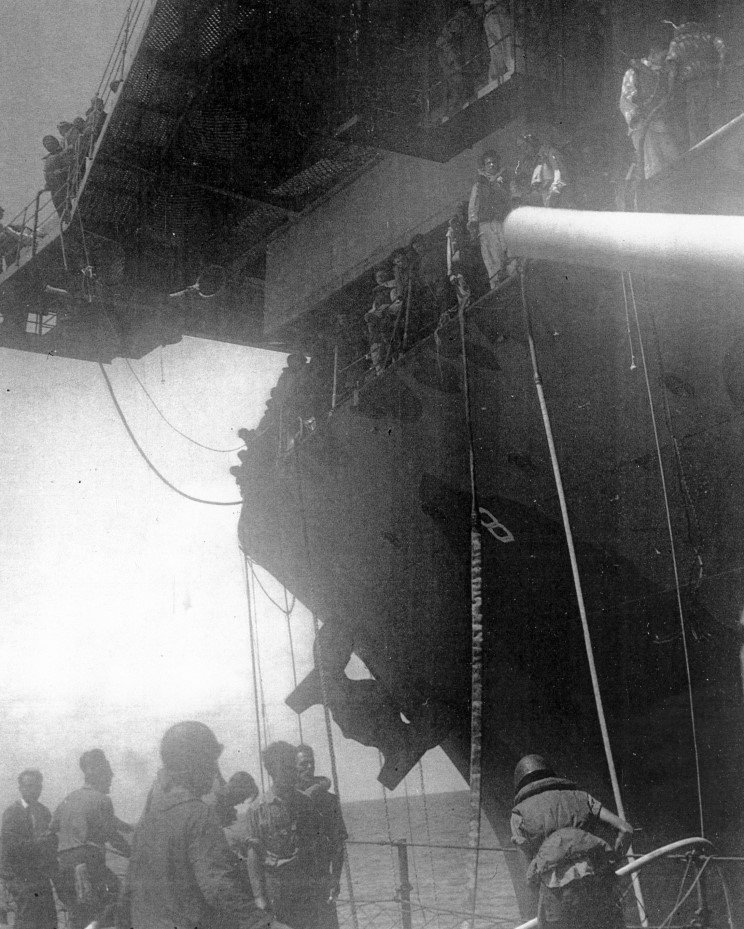
Also that is right about where the Val dive bomber crashed into the ship during the attack. Just forward of the port side 5" gun positions at foscle deck level.John W. wrote:Thanks, Mike, as always. I agree it's not vertical in that picture, and I'll look at the bow photos taken from NORTHAMPTON at the same time which I suspect will confirm what you say - flat on deck or removed. Noting the trip hazard, I suspect you are right it is removed and stowed somewhere nearby. When removed, I suspect there are fixed stanchions on either side of where the platform would be with removable chains across the opening, so an unbroken set of railings through that area would not be correct.
You can infer from my comments that I am back in action on HORNET again. Hope to post some updated photos in a week or two. I have pretty much completed the courses of hull shell plating (not using the tape or plastic shown in earlier photos on previous pages here), added airports / portholes (PITA), armor belt, bilge keels, props / shafts and such as required for a totally scratchbuilt hull. So far I have used exactly four parts from either kit - the Trump props which are pretty good when shaped up a bit. This has truly been by "I will never . . . (fill in blank)" model.
-
John W.
- Posts: 518
- Joined: Tue Mar 27, 2007 12:34 pm
- Location: Smithfield, Virginia
Re: Calling all USS Hornet CV-8 fans
Well, I have finally gotten back to, and maybe a bit further than, my last post showing pictures of my HORNET build in 2010. This is taking far longer than the entire life span of the original - from plans to grave.
I was not pleased with my earlier efforts to simulate the plate courses which are visible in most every shot of the HORNET from middle distance (say 1000 yards) and closer. So I went back to a bare, smooth hull and started over. These pictures, which are hopefully detailed enough to see what I have done, but not detailed enough to show some of the blemishes I still have to clean up, were taken today.
In this last picture one can see three of the only four kit parts (Trump or BWN) I have used to date - the props. Seriously, that's all.
Since I will be painting the hull soon, I need to revisit the position and size of the boottopping. I know it was discussed earlier in this thread but I went back through all 28 pages today and could not find the discussion. From photos and, to some extent the plans, it appears to me that the top of the boottop is in line with the top surface of the armor belt. That is, the topmost part of the armor belt is black - no 5N. I also recall that the height of the boottop is 6', or about 0.20" in 1/350. Am I correct in these statements?
I was not pleased with my earlier efforts to simulate the plate courses which are visible in most every shot of the HORNET from middle distance (say 1000 yards) and closer. So I went back to a bare, smooth hull and started over. These pictures, which are hopefully detailed enough to see what I have done, but not detailed enough to show some of the blemishes I still have to clean up, were taken today.
Since I will be painting the hull soon, I need to revisit the position and size of the boottopping. I know it was discussed earlier in this thread but I went back through all 28 pages today and could not find the discussion. From photos and, to some extent the plans, it appears to me that the top of the boottop is in line with the top surface of the armor belt. That is, the topmost part of the armor belt is black - no 5N. I also recall that the height of the boottop is 6', or about 0.20" in 1/350. Am I correct in these statements?
Some people make you happy, then they leave.
Others make you happy when they leave. (apologies to Oscar Wilde if he ever said anything similar, of which there is some doubt . . .)
Others make you happy when they leave. (apologies to Oscar Wilde if he ever said anything similar, of which there is some doubt . . .)