1/350 HMS Hood (scratchbuild)
Moderators: BB62vet, MartinJQuinn, JIM BAUMANN, Jon, Dan K
-
FlowerPower

- Posts: 235
- Joined: Wed Apr 03, 2013 7:05 pm
- Location: Netherlands
Re: 1/350 HMS Hood (scratchbuild)
madness!


WIP:
-1/72 Revell flower class corvette,with GLS PE and lots of Evergreen.
-1/350 Dragon Scharnhorst, Artwox wooden decks, CyberHobby PE, Master brass barrels.
-
EJFoeth
- Posts: 2911
- Joined: Wed Jan 21, 2009 1:51 pm
Re: 1/350 HMS Hood (scratchbuild)
With my previous pompom totally corroded away, I redesigned the model entirely and with more emphasis for easy construction and soldering. The first model is done and is unfortunately still "a prototype" as a forgot to add the holes at the top of the main gun block. That's quite important detail as you can see the top of the guns very well. I didn't make the gun block hollow for nothing! The angle of attack is fixed with the ammo trays fitting into slots in the mounting, but the traversing gear is fitted, just in case. For a different angle I need to etch the parts again (Hood had them at zero deg. angle) The rest of the parts are nearly error-free and the ease of construction has been greatly improved. One part broke of during handling at the end of the portside gun block. I'm not sure how to do the guns themselves; styrene and glue, or brass strip and soldering; I prefer the latter but need to either find or make strips at exactly the right sizes... Oh, all the detail of the sighting gear and pumps and drive haven't been added so this one is 'quite undetailed' 
So, the final errors have to be ironed out and the next batch can be etched.
So, the final errors have to be ironed out and the next batch can be etched.
-
LE BOSCO

- Posts: 2261
- Joined: Thu Aug 27, 2009 11:05 am
- Location: Paris France
Re: 1/350 HMS Hood (scratchbuild)
Hello EJFoeth
your pompom's are just sublimes the most accomplished I have seen at 350
Once again ,you put the helm very high
cheers
Nicolas
your pompom's are just sublimes
Once again ,you put the helm very high
cheers
Nicolas
-
EJFoeth
- Posts: 2911
- Joined: Wed Jan 21, 2009 1:51 pm
Re: 1/350 HMS Hood (scratchbuild)
Now back to the cable reels.... I had trouble with CA adhering to soldered brass. I hope the cleaner solved that...
-
109

- Posts: 627
- Joined: Sun Nov 16, 2008 7:56 am
- Contact:
Re: 1/350 HMS Hood (scratchbuild)
Beautiful Little gems!
Thanks & Sources: Nilsson (research) and J.Arntz (research, drawings).
-
Timmy C

- Posts: 12447
- Joined: Mon Jan 10, 2005 6:00 pm
- Location: Ottawa, Canada
Re: 1/350 HMS Hood (scratchbuild)
You're not going to ever paint this thing, are you?
De quoi s'agit-il?
-
mark_sch

- Posts: 178
- Joined: Mon Apr 13, 2009 8:42 pm
- Location: Fort Myers, Florida
Re: 1/350 HMS Hood (scratchbuild)
Your model is stunning!!!! Thank you for sharing the progress with us.
Mark
Mark
-
EJFoeth
- Posts: 2911
- Joined: Wed Jan 21, 2009 1:51 pm
Re: 1/350 HMS Hood (scratchbuild)
Thanks! And yes, it will be painted  Cable reels are 98% finished. I have to assemble one extra for the photo shoot and blog update...
-
richtea

- Posts: 381
- Joined: Sun Jul 19, 2009 10:33 am
- Location: Yorkshire, Great Britain
Re: 1/350 HMS Hood (scratchbuild)
What next EJ,
working breeches and ammo belts ?
Seriously, your attention to detail is first class, and your build is an inspiration to follow.
Regards
Richard
working breeches and ammo belts ?
Seriously, your attention to detail is first class, and your build is an inspiration to follow.
Regards
Richard
SI VIS PACEM,
PARA BELLUM
PARA BELLUM
-
EJFoeth
- Posts: 2911
- Joined: Wed Jan 21, 2009 1:51 pm
Re: 1/350 HMS Hood (scratchbuild)
Working breeches will be a bit too much, but 8 four-part guns will be added to the final model plus 8 ammo belts (four on top of the trays and four at the sides). These are to be added painted to the completed model. You cannot see the forward belts inside the gun block going over the outer barrels, otherwise I would have shown that 
The design for the quad pompom is in nearly the same state of complexity and readiness, but I ran out of space on the etch... this weapon is somewhat simpler but the connection of the ammo trays to the mount is more difficult.... I also made a version with splinter shields, unique to HMS Prince of Wales (AFAIK)
This is really fun to do, these small weapons. I'm really happy that they worked out after so much experimentation. If I exclude the costs of the new soldering equipment and supplies than a single pompom on my model costs over �50
(Perhaps I can issue it as a kit under my new "Rather Difficult Models" label )
)
The design for the quad pompom is in nearly the same state of complexity and readiness, but I ran out of space on the etch... this weapon is somewhat simpler but the connection of the ammo trays to the mount is more difficult.... I also made a version with splinter shields, unique to HMS Prince of Wales (AFAIK)
This is really fun to do, these small weapons. I'm really happy that they worked out after so much experimentation. If I exclude the costs of the new soldering equipment and supplies than a single pompom on my model costs over �50
(Perhaps I can issue it as a kit under my new "Rather Difficult Models" label
-
EJFoeth
- Posts: 2911
- Joined: Wed Jan 21, 2009 1:51 pm
Re: 1/350 HMS Hood (scratchbuild)
Blog update!
I�ve been exercising with soldering lately. I thought things were going wonderfully at first and I made a few fully soldered pompoms. Unfortunately, after a week they started to corrode and after a month parts started falling off. Repairs didn�t work and even superglue did no longer adhere to the metal at all (this never happened before!). I used the corrosion-free Tix flux that may have been the problem, either as I didn�t clean the parts properly afterwards or it simply isn�t corrosion free as some modelers on railroading forums claim? I don�t know really, but after a period of mourning for my pompoms I gathered my strength and I replaced all my soldering equipment and consumables. I finally found a nice Australian web shop called DCC Concepts with a nice how-to on soldering and their own range of solders and fluxes. They claim to have a no-clean non-toxic flux that I wanted to try and this solder/flux from DCC works really well. In the beginning I had some trouble as it didn�t run as smoothly as the Aber/Tix combination; however, that combination ran so well it ended up in a very very thin layer and a poor bond. I just have to be a bit more careful in the amount of solder I add for each joint.
I practiced on a new batch of cordage and hawser reels before trying the far more complicated pompom. I already made a batch but I had so much trouble gluing these parts together. If some part broke off during the final stages of construction, I really couldn�t repair it and had to start over. Understandably, the failure rate was very high.
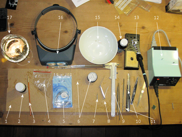
1. Piece of MDF used as a disposable workbench.
2. Bottle of flux secured in a hole drilled in the MDF. It does really help avoid knocking the bottle, which I did when working with the Tix flux earlier (Staining the modeling table). The first day I constantly found myself wanted to shift the position of the bottle but now I�m used to it not being able to move.
3. An old brush for applying the flux.
4. A bag of parts to be soldered.
5. The DCC Saphire solder.
6. Stock rod, tube, and wire. This brass from Scientific Wire can actually be soldered, in contrast to winding wire I bought that has a coating.
7. A drill to open freshly cut tubing.
8. A toe-nail clipper for cutting (thin) rod and wire.
9. Caliper.
10. Assortment of files, knifes and tweezers.
11. Part storage area outline.
12. Soldering station by Weller with a variable iron temperature.
13. Soldering iron with the finest tip in the Weller assortment of fine tips.
14. Alcohol for pre/post soldering cleaning.
15. Bowl with alcohol to finished parts.
16. Maximum magnification Optivisor to check the bonds and quality of filing and such.
17. Tramin 2011 Pinot Grigio from the Alto Adige. Hensel 2011 Grauer Burgunder will also work. Soothes the nerves before soldering, dampens disappointment when parts spontaneously disintegrate, raises spirits when things finally go according to plan.
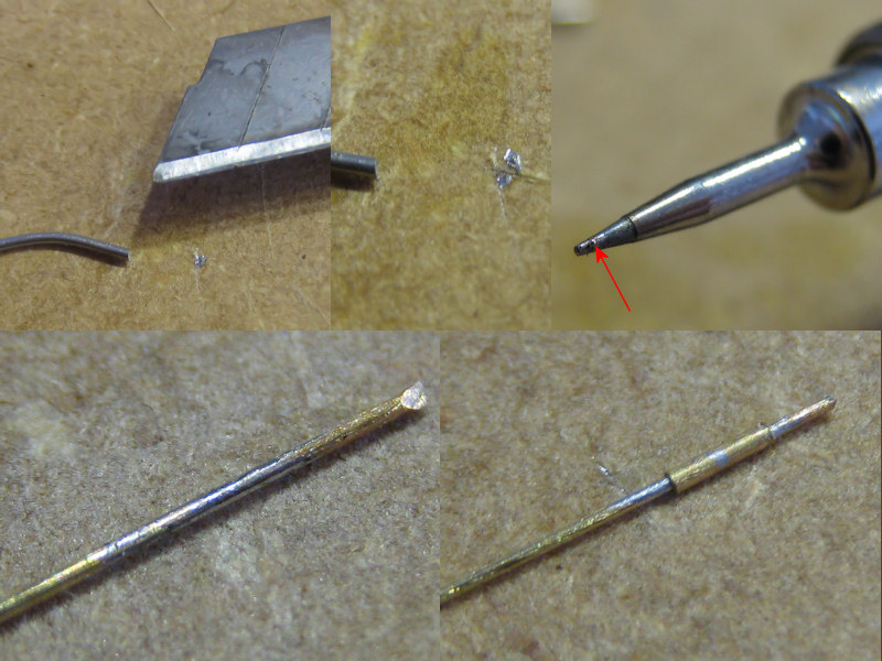
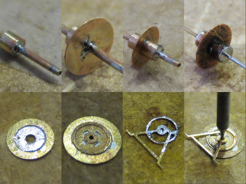
Now, I am not going to follow all the advice normally given for soldering work. For instance, I do not have an abrasive pen to clean the parts as the parts are much too small; holding them without damage is enough of a challenge already. Pre-tinning a part is often risky as you can clog delicate parts but sometimes works. You also can�t really pre-tin the soldering tip because the amount of solder you need is so small. Top-left shows a tiny chafing chipped from the solder. Now, slice is halved, and if necessary cut it two again. You can pick up the solder with the tip of the iron; you can see a tiny bead (top right. note that this is the smallest soldering iron tip that Weller sells with a 0.4mm tip). This works very well for applying a minute amount of solder that is sometimes already a bit too much. The bottom images show a tiny 0.5mm tube soldered to a 0.3mm wire; the wire centers the etched parts and the tube acts a spacer. I add flux to the wire, pre-tin the wire (no harm here), slide over the tube and add heat.
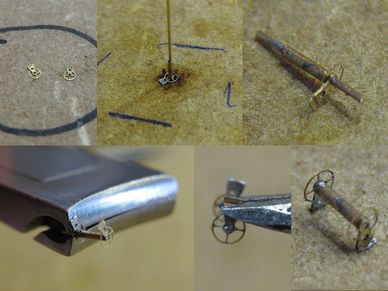
The two etched parts are cut from the fret, sanded and put in the �storage area outline�; they are so small and difficult to find that putting them on the same spot actually helps. Now, I drilled in a small 0.3mm hole on the base plate so that I can plug the 0.3 wire through the etched part (top center), add some flux and then heat while gently pushing the tube down with fine-tipped tweezers. The part is both held in place and aligned at the same time. It can help to use to Optivisor to see if the solder is really flowing; if the connection is bad the part will probably fall off anyway. The long end of the wire is clipped and the other etched part is added. This is more difficult as they need to be aligned with respect to each other and there is some risk of the first part getting loose, so some trial and error is required.
My cheap model pliers weren�t any good for clipping wire (most modeling tools aren�t) but my beautiful Zwilling toenail clippers were just perfect for the job. Afterwards the excess wire (nearly nothing) was filed off; this is a tricky part as it�s very easy to catapult the part if you�re not careful (need better tweezers). Afterwards the etched parts were folded. Here the optivisor came in really handy, showing me if I held the tweezers properly over the fold line. The image bottom left shows a poor example, risking folding over a hole present in the part. Bottom right shows a finished cordage reel; 2.5mm wide.
The hawser reels presented a much greater challenge; I needed to make drums with a 0.3mm hole for the center wire to align all parts. However, I haven�t been successful drilling in these small holes in brass. I started with a center drill of 0.5mm, giving only a gently tap to the end of the rod, but the small drill often wandered anyway. Even when the hole was centered perfectly the drill breaks, even when I drill very carefully using cutting oil and cleaning the drill every few tenths of a millimeter. Anyway, I gave up and ordered some stock tubing from Albion Alloys with a 0.3/0.5 inner/outer diameter. Drilling in a 0.5mm hole is very much easier and the tubes are very easy to cut to length
Making small brass tubes is now fairly easy for me. Setting the late at its highest rpm (only 3,000) I start with cutting the end of the stock brass (1) and cutting the rod to the correct diameter in very small steps (2). I bought some stock rod from Albion at the right diameter but I lost it... Next I position the 0.5mm hole with the center drill but I do not drill the hole yet (3). I change the cutting tool for the parting tool (the quick change tool holder is the best upgrade for the lathe). I position the parting tool, release the rod,push the rod back with the parting tool and fix the rod again in the chuck. This is my primitive way to reposition the parting tool at zero (4) and make a small groove with the parting tool (5). Then I apply the square flat file; I put the lathe in reverse so that the file isn't catapulted into my eye when I accidentally hit the chuck with the end. I think this is much safer (6). I continue slowly with the parting tool (7) and capture the small tube on the end of the drill (or center drill). I usually make a batch of them before reinserting them in the chuck (9), apply some cutting oil and drill them through.
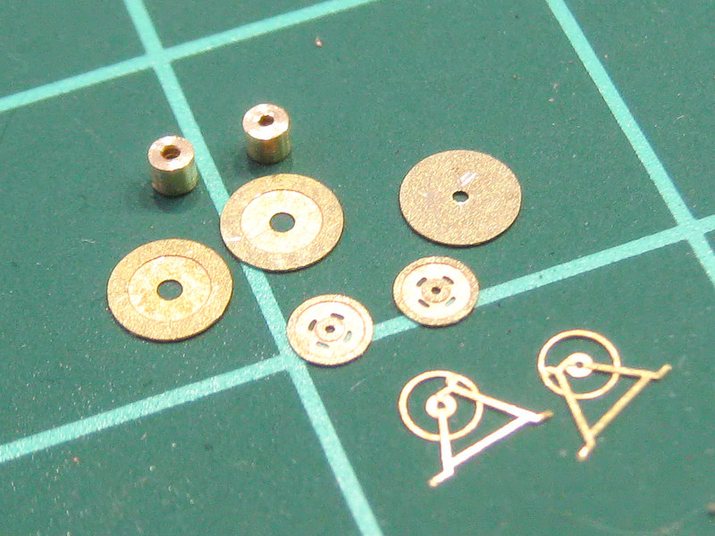
I took a few images of the largest hawser reel, consisting of 2 tubes and 7 etched parts.
The top four images show the small drums added to the 0.5mm tube. The tube is much to long but when the to tubes are soldered to each, I insert the part in my hand-held drill and cut the tube by hand. A small 0.3mm wire is then put through the tube. The etched parts at the side are actually three parts, so that I could capture a bit more detail. The first parts fit into each other and need to aligning, but the last part is held in placed by an old broken-off 0.3mm drill.
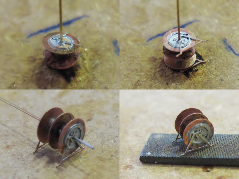
Like the cordage reel,. the hawsers are fixed to the bade plate and the parts are all soldered into place. This is a tricky part because all the parts get desoldered; I apply pressure with fine-tipped tweezers while the solder solidifies. The part is checked to see if everything still aligns nicely and of all the feel touch the deck properly; if not, the part is heated and realigned. The 0.3mm is then trimmed and filed smooth.
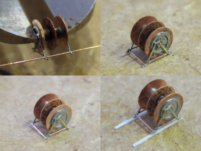
The small model is clamped into the caliper and a 0.15mm brass wire is soldered into place, cut to size and filed. If the rod breaks off during filing, then the bond wasn't any good. Although the flux is sold as no-clean flux, I threw the parts int he ultrasonic cleaner anyway. This cleaned up the parts and improved the bond between the final two parts superglued to base of the small models.
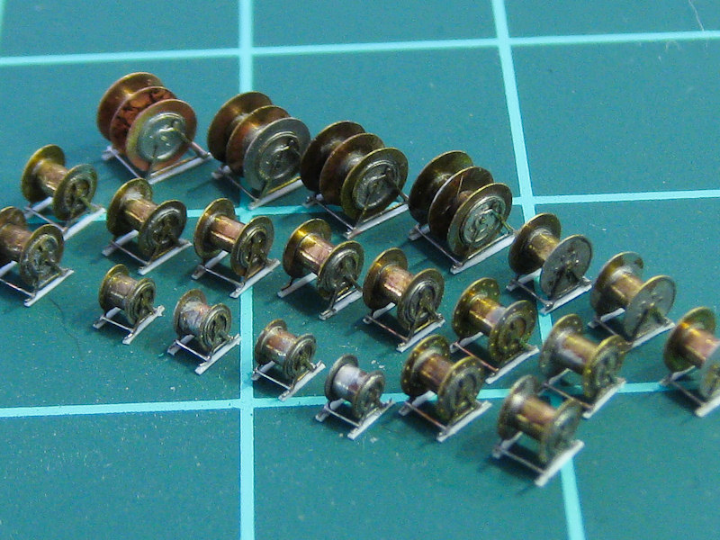
Not the best picture, bit it givens a nice impression of the range of reels to be fitted to the model. Why doesn't the reel at the center doesn't have those two wires? Must be a failure I didn't throw out.
I�ve been exercising with soldering lately. I thought things were going wonderfully at first and I made a few fully soldered pompoms. Unfortunately, after a week they started to corrode and after a month parts started falling off. Repairs didn�t work and even superglue did no longer adhere to the metal at all (this never happened before!). I used the corrosion-free Tix flux that may have been the problem, either as I didn�t clean the parts properly afterwards or it simply isn�t corrosion free as some modelers on railroading forums claim? I don�t know really, but after a period of mourning for my pompoms I gathered my strength and I replaced all my soldering equipment and consumables. I finally found a nice Australian web shop called DCC Concepts with a nice how-to on soldering and their own range of solders and fluxes. They claim to have a no-clean non-toxic flux that I wanted to try and this solder/flux from DCC works really well. In the beginning I had some trouble as it didn�t run as smoothly as the Aber/Tix combination; however, that combination ran so well it ended up in a very very thin layer and a poor bond. I just have to be a bit more careful in the amount of solder I add for each joint.
I practiced on a new batch of cordage and hawser reels before trying the far more complicated pompom. I already made a batch but I had so much trouble gluing these parts together. If some part broke off during the final stages of construction, I really couldn�t repair it and had to start over. Understandably, the failure rate was very high.
1. Piece of MDF used as a disposable workbench.
2. Bottle of flux secured in a hole drilled in the MDF. It does really help avoid knocking the bottle, which I did when working with the Tix flux earlier (Staining the modeling table). The first day I constantly found myself wanted to shift the position of the bottle but now I�m used to it not being able to move.
3. An old brush for applying the flux.
4. A bag of parts to be soldered.
5. The DCC Saphire solder.
6. Stock rod, tube, and wire. This brass from Scientific Wire can actually be soldered, in contrast to winding wire I bought that has a coating.
7. A drill to open freshly cut tubing.
8. A toe-nail clipper for cutting (thin) rod and wire.
9. Caliper.
10. Assortment of files, knifes and tweezers.
11. Part storage area outline.
12. Soldering station by Weller with a variable iron temperature.
13. Soldering iron with the finest tip in the Weller assortment of fine tips.
14. Alcohol for pre/post soldering cleaning.
15. Bowl with alcohol to finished parts.
16. Maximum magnification Optivisor to check the bonds and quality of filing and such.
17. Tramin 2011 Pinot Grigio from the Alto Adige. Hensel 2011 Grauer Burgunder will also work. Soothes the nerves before soldering, dampens disappointment when parts spontaneously disintegrate, raises spirits when things finally go according to plan.
Now, I am not going to follow all the advice normally given for soldering work. For instance, I do not have an abrasive pen to clean the parts as the parts are much too small; holding them without damage is enough of a challenge already. Pre-tinning a part is often risky as you can clog delicate parts but sometimes works. You also can�t really pre-tin the soldering tip because the amount of solder you need is so small. Top-left shows a tiny chafing chipped from the solder. Now, slice is halved, and if necessary cut it two again. You can pick up the solder with the tip of the iron; you can see a tiny bead (top right. note that this is the smallest soldering iron tip that Weller sells with a 0.4mm tip). This works very well for applying a minute amount of solder that is sometimes already a bit too much. The bottom images show a tiny 0.5mm tube soldered to a 0.3mm wire; the wire centers the etched parts and the tube acts a spacer. I add flux to the wire, pre-tin the wire (no harm here), slide over the tube and add heat.
The two etched parts are cut from the fret, sanded and put in the �storage area outline�; they are so small and difficult to find that putting them on the same spot actually helps. Now, I drilled in a small 0.3mm hole on the base plate so that I can plug the 0.3 wire through the etched part (top center), add some flux and then heat while gently pushing the tube down with fine-tipped tweezers. The part is both held in place and aligned at the same time. It can help to use to Optivisor to see if the solder is really flowing; if the connection is bad the part will probably fall off anyway. The long end of the wire is clipped and the other etched part is added. This is more difficult as they need to be aligned with respect to each other and there is some risk of the first part getting loose, so some trial and error is required.
My cheap model pliers weren�t any good for clipping wire (most modeling tools aren�t) but my beautiful Zwilling toenail clippers were just perfect for the job. Afterwards the excess wire (nearly nothing) was filed off; this is a tricky part as it�s very easy to catapult the part if you�re not careful (need better tweezers). Afterwards the etched parts were folded. Here the optivisor came in really handy, showing me if I held the tweezers properly over the fold line. The image bottom left shows a poor example, risking folding over a hole present in the part. Bottom right shows a finished cordage reel; 2.5mm wide.
The hawser reels presented a much greater challenge; I needed to make drums with a 0.3mm hole for the center wire to align all parts. However, I haven�t been successful drilling in these small holes in brass. I started with a center drill of 0.5mm, giving only a gently tap to the end of the rod, but the small drill often wandered anyway. Even when the hole was centered perfectly the drill breaks, even when I drill very carefully using cutting oil and cleaning the drill every few tenths of a millimeter. Anyway, I gave up and ordered some stock tubing from Albion Alloys with a 0.3/0.5 inner/outer diameter. Drilling in a 0.5mm hole is very much easier and the tubes are very easy to cut to length
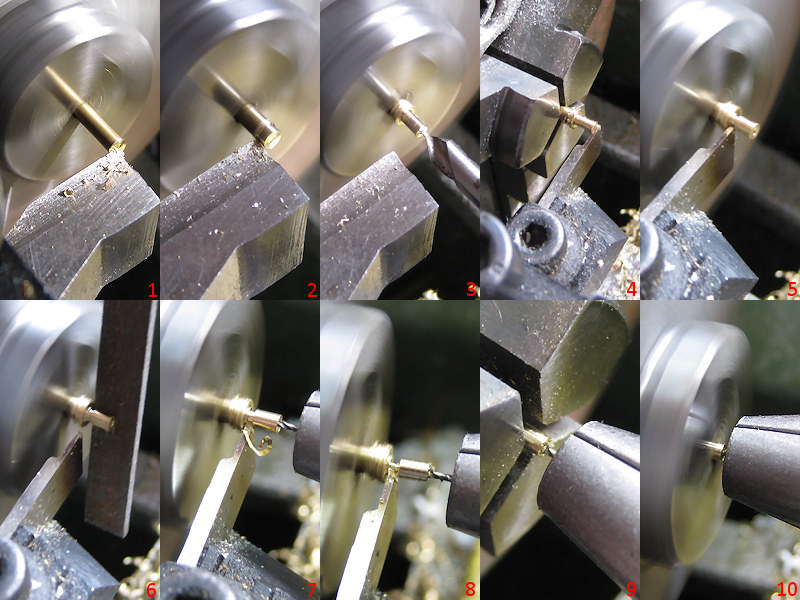
Making small brass tubes is now fairly easy for me. Setting the late at its highest rpm (only 3,000) I start with cutting the end of the stock brass (1) and cutting the rod to the correct diameter in very small steps (2). I bought some stock rod from Albion at the right diameter but I lost it... Next I position the 0.5mm hole with the center drill but I do not drill the hole yet (3). I change the cutting tool for the parting tool (the quick change tool holder is the best upgrade for the lathe). I position the parting tool, release the rod,push the rod back with the parting tool and fix the rod again in the chuck. This is my primitive way to reposition the parting tool at zero (4) and make a small groove with the parting tool (5). Then I apply the square flat file; I put the lathe in reverse so that the file isn't catapulted into my eye when I accidentally hit the chuck with the end. I think this is much safer (6). I continue slowly with the parting tool (7) and capture the small tube on the end of the drill (or center drill). I usually make a batch of them before reinserting them in the chuck (9), apply some cutting oil and drill them through.
I took a few images of the largest hawser reel, consisting of 2 tubes and 7 etched parts.
The top four images show the small drums added to the 0.5mm tube. The tube is much to long but when the to tubes are soldered to each, I insert the part in my hand-held drill and cut the tube by hand. A small 0.3mm wire is then put through the tube. The etched parts at the side are actually three parts, so that I could capture a bit more detail. The first parts fit into each other and need to aligning, but the last part is held in placed by an old broken-off 0.3mm drill.
Like the cordage reel,. the hawsers are fixed to the bade plate and the parts are all soldered into place. This is a tricky part because all the parts get desoldered; I apply pressure with fine-tipped tweezers while the solder solidifies. The part is checked to see if everything still aligns nicely and of all the feel touch the deck properly; if not, the part is heated and realigned. The 0.3mm is then trimmed and filed smooth.
The small model is clamped into the caliper and a 0.15mm brass wire is soldered into place, cut to size and filed. If the rod breaks off during filing, then the bond wasn't any good. Although the flux is sold as no-clean flux, I threw the parts int he ultrasonic cleaner anyway. This cleaned up the parts and improved the bond between the final two parts superglued to base of the small models.
Not the best picture, bit it givens a nice impression of the range of reels to be fitted to the model. Why doesn't the reel at the center doesn't have those two wires? Must be a failure I didn't throw out.
-
LE BOSCO
- Posts: 2261
- Joined: Thu Aug 27, 2009 11:05 am
- Location: Paris France
Re: 1/350 HMS Hood (scratchbuild)
hello EJFoeth
I bow to all the know-how! for giving me the want to progress,you are one of my masters to whom I owe an eternal reconaisance it's just grandiose
cheers
Nicolas
cheers
Nicolas
-
EJFoeth
- Posts: 2911
- Joined: Wed Jan 21, 2009 1:51 pm
Re: 1/350 HMS Hood (scratchbuild)
Thanks! I'm happy the results turned out so nice. I reread my post on part of these small models and I'm glad it went better this time...!
-
Rob 2

- Posts: 157
- Joined: Sun Apr 11, 2010 1:22 pm
Re: 1/350 HMS Hood (scratchbuild)
It's always a pleasure to watch you work EJ.
The results are stunning.
Rob.
The results are stunning.
Rob.
-
EJFoeth
- Posts: 2911
- Joined: Wed Jan 21, 2009 1:51 pm
Re: 1/350 HMS Hood (scratchbuild)
Continuiing from part I
With the soldering going so well I decided to solder on a bit more and had some parts redesigned and etched.

Some minor detail was added first. The two ladders on the inside of the funnel are placed with a jig so that the gantry will link up to it nicely. The ladder is by Aber, one of the few commercial products I have used (I�ll probably use my own ladders in the future). The steam pipes cluttered around the funnel are made from rod; drilled in, chopped up to give it that knuckle on the end, and fixed with brass wire. That is, I didn�t glue the pipes to the wire yet to avoid handling damage in that area.

Note that there is a bit of damage on the aft funnel that was later patched up; a nice piece of detail to add. The top left image also shows the typical Royal Navy approach to painting the ship; they do not use the foot rails found on axis battleships with a series of pulleys and planks to stand on. It doesn�t seem very safe but it does save you building an awful lot of these foot rails. The pulleys are etched parts, folded once.

Here�s a sketch of the inside of the funnel. There is a gantry and a funnel grill. The crew could access the funnel from below, climb to the top and fix an awning to the grill (but usually did so only when the boilers were out). I made this small drawing in Autocad of the funnel grill with a series of 0.2mm holes for the supports of the grill and for a few pins to hold the grill in place. A ring goes around the funnel cap supporting a series of arches. One large grande arche is on the ship center line. I decided to make a drilling template for the supports and support pins.

The inside of the funnel isn�t as perfect as I�d hoped and deformed a bit with all these layers of plastic going around it. Perhaps all these brass wires in the inside are a bit too taut. I already botched up fitting several well-executed gantries so I came up with a disposable fitting template to check the goodness of fit; should have come up with that earlier!

The soldering of the gantry itself was slightly tricky and I had to tape the parts down at every step. I added the solder like I�d normally add CA; a few spots to fix the part, with a line of solder when it�s more or less in place.

Now the template for the grill. I bought a pin chuck to hold the 0.2mm drills. When I put the pin chuck in the Proxxon chuck (R�hm actually) and dutifully fixed the chuck with the key at all three positions as my tool shop ordered me to do, the pin chuck was not centered correctly; I really had to try, try and try again until it was finally worked. ( bought a new R�hm chuck so that I now have a nicely centered chuck/pin chuck combination never to be separated. I made a picture of the spinning drill as proof it finally worked. I started with the drill protruding only a few mms from the chuck but the drill will usually walk away slightly---drilling off center---and the drill will break when the chuck is near the work piece; I lost three drills before I figured this out. So, I finally had the drill sticking about 1 cm or so from the chuck so that it could flex. The result is shown at right after drilling and with the positioning pins. The tubes at the center are supports for the arcs of the grill, made from aluminum so that the brass wire won�t be soldered to them.

I had some room to spare on my last etch so I added a folding template for the ring of the grill; the brass was far too stiff to use this template but it did work to check the shape. I started by rolling the handle of my X-acto knife over a 0.2mm brass wire until the diameter was correct. With some pressure from a pair of pliers I added the parallel center until the shape was more or less right. The wire was transferred to the jig, held in place by tape and the supports were added one by one. I started opposite where the ends of the ring meet and cut the ring to size only when nearly all supports were in place. The positioning pins could then be removed.

The arcs were bent into shape and checked against a high-tech drawing. The grande arche was added first, followed by the other arches. Note that the ends of each arc have a 90-degree bend; this allowed me to temporarily tape the arc to the jig and keep the direction of the arc upwards; otherwise it will just fall over all the time. I fixed the end of a single arch to the grande arch, fix the arch to the ring, and reapply to both ends in succession. By doing this, there is no stress in the solder and when I apply heat to the center they do not change position (much).

Afterwards three etched parts were added on top of the intersections of all the arcs. The difficulty was not so much avoiding the desoldering of all arcs but aligning the etchings themselves. The grill could then be lifted from the jig. One grill was damaged beyond repair at this phase. One grill took between five and six hours to make; this time was mainly spent looking through the Optivisor and handling the parts with tweezers and the soldering iron until the alignment was to my satisfaction (which is never, naturally).

These funnels took more than a fair amount of planning and experimentation but now have a level of detail that I would not have thought possible a few years ago (grill and gantry are not fixed yet in this picture). The soldering allows for much better and clearer work than using super glue and it is much easier to correct.
Done
With the soldering going so well I decided to solder on a bit more and had some parts redesigned and etched.
Some minor detail was added first. The two ladders on the inside of the funnel are placed with a jig so that the gantry will link up to it nicely. The ladder is by Aber, one of the few commercial products I have used (I�ll probably use my own ladders in the future). The steam pipes cluttered around the funnel are made from rod; drilled in, chopped up to give it that knuckle on the end, and fixed with brass wire. That is, I didn�t glue the pipes to the wire yet to avoid handling damage in that area.
Note that there is a bit of damage on the aft funnel that was later patched up; a nice piece of detail to add. The top left image also shows the typical Royal Navy approach to painting the ship; they do not use the foot rails found on axis battleships with a series of pulleys and planks to stand on. It doesn�t seem very safe but it does save you building an awful lot of these foot rails. The pulleys are etched parts, folded once.
Here�s a sketch of the inside of the funnel. There is a gantry and a funnel grill. The crew could access the funnel from below, climb to the top and fix an awning to the grill (but usually did so only when the boilers were out). I made this small drawing in Autocad of the funnel grill with a series of 0.2mm holes for the supports of the grill and for a few pins to hold the grill in place. A ring goes around the funnel cap supporting a series of arches. One large grande arche is on the ship center line. I decided to make a drilling template for the supports and support pins.
The inside of the funnel isn�t as perfect as I�d hoped and deformed a bit with all these layers of plastic going around it. Perhaps all these brass wires in the inside are a bit too taut. I already botched up fitting several well-executed gantries so I came up with a disposable fitting template to check the goodness of fit; should have come up with that earlier!
The soldering of the gantry itself was slightly tricky and I had to tape the parts down at every step. I added the solder like I�d normally add CA; a few spots to fix the part, with a line of solder when it�s more or less in place.
Now the template for the grill. I bought a pin chuck to hold the 0.2mm drills. When I put the pin chuck in the Proxxon chuck (R�hm actually) and dutifully fixed the chuck with the key at all three positions as my tool shop ordered me to do, the pin chuck was not centered correctly; I really had to try, try and try again until it was finally worked. ( bought a new R�hm chuck so that I now have a nicely centered chuck/pin chuck combination never to be separated. I made a picture of the spinning drill as proof it finally worked. I started with the drill protruding only a few mms from the chuck but the drill will usually walk away slightly---drilling off center---and the drill will break when the chuck is near the work piece; I lost three drills before I figured this out. So, I finally had the drill sticking about 1 cm or so from the chuck so that it could flex. The result is shown at right after drilling and with the positioning pins. The tubes at the center are supports for the arcs of the grill, made from aluminum so that the brass wire won�t be soldered to them.
I had some room to spare on my last etch so I added a folding template for the ring of the grill; the brass was far too stiff to use this template but it did work to check the shape. I started by rolling the handle of my X-acto knife over a 0.2mm brass wire until the diameter was correct. With some pressure from a pair of pliers I added the parallel center until the shape was more or less right. The wire was transferred to the jig, held in place by tape and the supports were added one by one. I started opposite where the ends of the ring meet and cut the ring to size only when nearly all supports were in place. The positioning pins could then be removed.
The arcs were bent into shape and checked against a high-tech drawing. The grande arche was added first, followed by the other arches. Note that the ends of each arc have a 90-degree bend; this allowed me to temporarily tape the arc to the jig and keep the direction of the arc upwards; otherwise it will just fall over all the time. I fixed the end of a single arch to the grande arch, fix the arch to the ring, and reapply to both ends in succession. By doing this, there is no stress in the solder and when I apply heat to the center they do not change position (much).
Afterwards three etched parts were added on top of the intersections of all the arcs. The difficulty was not so much avoiding the desoldering of all arcs but aligning the etchings themselves. The grill could then be lifted from the jig. One grill was damaged beyond repair at this phase. One grill took between five and six hours to make; this time was mainly spent looking through the Optivisor and handling the parts with tweezers and the soldering iron until the alignment was to my satisfaction (which is never, naturally).
These funnels took more than a fair amount of planning and experimentation but now have a level of detail that I would not have thought possible a few years ago (grill and gantry are not fixed yet in this picture). The soldering allows for much better and clearer work than using super glue and it is much easier to correct.
Done
-
LE BOSCO
- Posts: 2261
- Joined: Thu Aug 27, 2009 11:05 am
- Location: Paris France
Re: 1/350 HMS Hood (scratchbuild)
Woohoooo! EJFoeth I used my poor vocabulary (in English)!it's wonderful of fineness and realism
comgrat's
Nicolas
comgrat's
Nicolas
-
EJFoeth
- Posts: 2911
- Joined: Wed Jan 21, 2009 1:51 pm
Re: 1/350 HMS Hood (scratchbuild)
Thanks! So, when are you going to do Jean Bart at Casablanca? Uncompleted turret B, battle damage from the shelling and bombing, harbour scene... should be wonderful...!
-
LE BOSCO
- Posts: 2261
- Joined: Thu Aug 27, 2009 11:05 am
- Location: Paris France
Re: 1/350 HMS Hood (scratchbuild)
EJFoeth wrote:..... when are you going to do Jean Bart at Casablanca? Uncompleted turret B, battle damage from the shelling and bombing, harbour scene... .!
this is not at the program! but, why not ,a day
nicolas
-
MartinJQuinn

- Posts: 8532
- Joined: Tue Jan 11, 2005 1:40 pm
- Location: New Jersey
Re: 1/350 HMS Hood (scratchbuild)
The work on the funnels is madness. Simply madness. And you make it looks so damn simple.
Martin
"Tomorrow is the most important thing in life. Comes into us at midnight very clean. It's perfect when it arrives and it puts itself in our hands. It hopes we've learned something from yesterday." John Wayne
Ship Model Gallery
"Tomorrow is the most important thing in life. Comes into us at midnight very clean. It's perfect when it arrives and it puts itself in our hands. It hopes we've learned something from yesterday." John Wayne
Ship Model Gallery
-
EJFoeth
- Posts: 2911
- Joined: Wed Jan 21, 2009 1:51 pm
Re: 1/350 HMS Hood (scratchbuild)
I should have a time-lapse video of me while building; about an hour of failure and a minute of modeling going well There really is a lot of trial and error involved and it was really difficult to do. The drills cost around $7.5 so breaking one after the other is unnerving; my mood was really getting the worst of it at that time. I spent hours trying to get the drilling jig correct; first I tried without the pin chuck ($40) and bought a new normal chuck ($15). The old old chuck was complete lodged and I spent an hour or so getting it off the drill press. I briefly thought I had to buy a new drill press because the drill press I have flexes slightly. The etched gantry is version #3! #1 in steel that doesn't glue very well; then a version where it was impossible to align the walkway and the main platform. And so on. Every blog posts usually runs over several months with all the intermediate failures I have to solve. For example, I ruined one grill because I didn't use the aluminum tubing in the center but a bit of wood. That wood was burned by the soldering iron and the result was a bad grill. That is one day lost... fortunately I had one week of vacation to finish up the funnels and used most of that time. One funnel stills needs a bit of work the correct the inside and add the rest of the ladders.
Anyway, for me modeling is mostly about solving all these problems! I refuse to give up, even though at the end of the week I have a funnel grill and not a completed model....
Anyway, for me modeling is mostly about solving all these problems! I refuse to give up, even though at the end of the week I have a funnel grill and not a completed model....