Here is some interesting "learning curve" information.
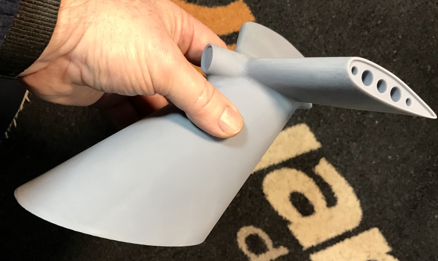
I tried hollowing the arms and used the same 3 second exposure time as last time. I started to do this by hand, and then remembered Chitubox had a hollowing tool. And it could also put supports inside and punch drain holes. Here is the result:
It does a pretty good job, and is a lot faster than trying to build the interior surfaces and supports in the CAD program!
So how did it work?
This is the bottom of the port launcher arm. You can see the two drain holes - which are actually mounting holes for stubs on the missiles - and the launcher rails. The "key hole" in the end of the cylindrical part was extended into the interior for another drain hole. This is the best print yet! The port arm was almost perfect.
The starboard arm had some problems. It had the same two drain holes between the launcher rails as the port side, but I added another drain hole on the top of the cylindrical part close to the "key". This part of the arm is inside the launcher trunnion support and will not be visible.
Notice the front of the outboard launcher rail in these two pictures:
The port arm rail end came out square, and this is good.
The starboard arm rail was deformed upward. Bad!
So what's the problem? Look at these two pictures of the Chitubox supports:
Chitubox doesn't add enough supports by default, so I added a lot more, including supports at the very front end of the rail.
On the starboard arm I added a lot of extra supports, but I didn't put one right at the front of the rail. So it flexed as the print was being pulled from the film. Lesson learned!
There was another failure on the starboard arm.
This is the port arm Emergency Igniter (arrow). If the TALOS missile booster failed to ignite when we pulled the trigger we had a problem. It might ignite at any time so we certainly didn't want to take it back into the missile house! When the 4000 pounds of class B explosives ignited it accelerated the 7500 pound missile/booster to Mach 2.2 at a range of 8 miles in 5 seconds. Makes fuel dragsters look like kids toys! The booster exhaust flame was about 75-80 feet long, a real blowtorch! It wasn't something you wanted inside a magazine containing 200,000 pounds of explosives!
The Emergency Igniter arm carried a black powder charge in the can on the end (arrow) and could be swung down behind the booster. The arm rammed the charge into the booster nozzle and then it was ignited. No more problem (unless the Emergency Igniter failed).
The starboard Igniter didn't print correctly.
This is the default Chitubox support position and it worked OK.
This is the starboard arm supports. It was initially like the port side, but I moved the contact point a bit because it leaves a bit of support attached to the thin end ring on the Igniter can. My fault!
So the moral of this story is two-fold.
1. Try to hollow out any parts that have increasing cross sections as they print, like horizontal cylinders. The forces needed to separate the print from the plastic window over the LCD will increase with each step until they are great enough to break any supports. Hollowing the part reduces the cross section against the plastic and therefore the separation forces.
2. Always support the ends of parts. Parts that overhang their supports may flex when they are separated from the film, and will not print correctly.
So now I have 18 bad parts and two port arms that are good enough to use. And a bit better knowledge of how to get a successful print.
Phil
A collision at sea will ruin your entire day. Aristotle