Hello:
Just for fun, I pulled out the other USS Enterprise to see how much things changed. It's a bit sad that the two Enterprises just missed overlapping. They were never side by side, it would have been quite a sight if the were.
I would also like to add that seeing them side-by-side drove home the colossal undertaking that building CVN-65 would be. CV-6 is a big project, starting from a much newer kit. CVN-65 is a much older kit (but Tamiya), and the mount of detailing that could be thrown at it is staggering. I've wanted to do CV-6 for a long time, so I'm motivated to see it done. I don't know where or how I'd get the mojo to tackle CVN-65.
Mike
1/350 USS Enterprise CV-6
Moderators: BB62vet, MartinJQuinn, JIM BAUMANN, Jon, Dan K
-
mconnelley
- Posts: 251
- Joined: Sun Feb 07, 2010 8:13 pm
Re: 1/350 USS Enterprise CV-6
- Attachments
-
-
Last edited by mconnelley on Mon Feb 20, 2023 3:52 am, edited 1 time in total.
-
marijn van gils
- Posts: 2691
- Joined: Tue Feb 06, 2007 10:24 am
- Location: Belgium
Re: 1/350 USS Enterprise CV-6
Nice! 
And for additional contrast, you can add one of the former Enterprises too :
:
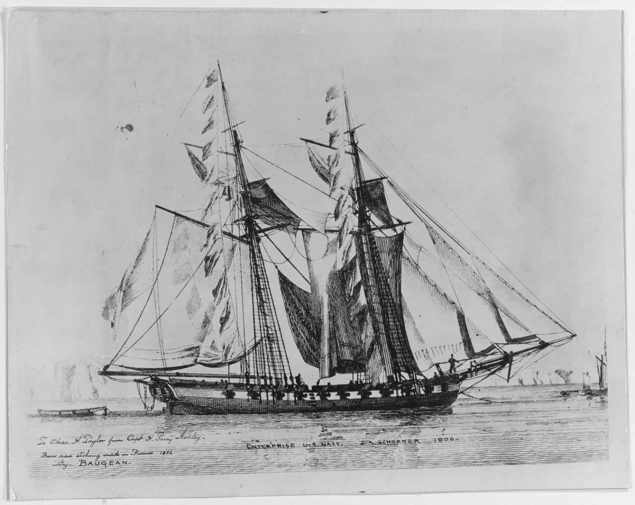
And for additional contrast, you can add one of the former Enterprises too
: -
mconnelley
- Posts: 251
- Joined: Sun Feb 07, 2010 8:13 pm
Re: 1/350 USS Enterprise CV-6
Hello:
By popular demand, I am pleased to present the 1799 USS Enterprise in 1:350 scale!
It's so tiny. The real thing was 85' long. Some of the motor launches carried by the Big E were 50', so the Little-E wasn't much larger than the motor launches used in WW2. They must have been very brave to sail across the Atlantic and take into combat a ship that today would be used for an afternoon pleasure cruise.
I made my Little-E from one of the boats from the 1/200 Arizona kit, which happens to be within a few millimeters of the right length for the 1799 Enterprise. I added some stretched sprue and plastic rod for the masts, some tissue paper for sails held on with some Tamiya tape. Actually a fun little project, and it'd be interesting to do it properly some day, as I've never tried to build a sailing ship (before today at least).
Mike
By popular demand, I am pleased to present the 1799 USS Enterprise in 1:350 scale!
It's so tiny. The real thing was 85' long. Some of the motor launches carried by the Big E were 50', so the Little-E wasn't much larger than the motor launches used in WW2. They must have been very brave to sail across the Atlantic and take into combat a ship that today would be used for an afternoon pleasure cruise.
I made my Little-E from one of the boats from the 1/200 Arizona kit, which happens to be within a few millimeters of the right length for the 1799 Enterprise. I added some stretched sprue and plastic rod for the masts, some tissue paper for sails held on with some Tamiya tape. Actually a fun little project, and it'd be interesting to do it properly some day, as I've never tried to build a sailing ship (before today at least).
Mike
- Attachments
-
-
NavyShooter

- Posts: 292
- Joined: Sun Jul 03, 2011 5:10 pm
- Location: Windsor Junction NS
Re: 1/350 USS Enterprise CV-6
That's beautiful!mconnelley wrote:Hello:
By popular demand, I am pleased to present the 1799 USS Enterprise in 1:350 scale!
It's so tiny. The real thing was 85' long. Some of the motor launches carried by the Big E were 50', so the Little-E wasn't much larger than the motor launches used in WW2. They must have been very brave to sail across the Atlantic and take into combat a ship that today would be used for an afternoon pleasure cruise.
I made my Little-E from one of the boats from the 1/200 Arizona kit, which happens to be within a few millimeters of the right length for the 1799 Enterprise. I added some stretched sprue and plastic rod for the masts, some tissue paper for sails held on with some Tamiya tape. Actually a fun little project, and it'd be interesting to do it properly some day, as I've never tried to build a sailing ship (before today at least).
Mike

You could almost fit it on an elevator!
ICBM Address: 44:78N 063:63W
Ex RCN, HMC Ships Gatineau, Athabaskan, Charlottetown, St. John's, Montreal, Charlottetown, Summerside, Montreal.
Ex RCN, HMC Ships Gatineau, Athabaskan, Charlottetown, St. John's, Montreal, Charlottetown, Summerside, Montreal.
-
mconnelley
- Posts: 251
- Joined: Sun Feb 07, 2010 8:13 pm
Re: 1/350 USS Enterprise CV-6
Hello:
Back to *ahem* serious modeling now. I'm more or less done with the prop shafts. Since the last update, I thinned the outboard aft struts.
There is a shaft support and associated struts half way along each shaft, which on the kit are represented by one very thick strut. Also, the mid-shaft support is beveled on one side but not the other, whereas it should be beveled on both sides. I clipped off the thick strut, then chucked the part into a power drill to turn like it's on a lathe to put the bevel into the flat face. I slid the support onto the shaft (to ensure that the support is in the right place with the right alignment), then used some sheet plastic to make some new struts (pre-beveled on the fore and aft ends), and glued the new struts into place. Repeat 3 more times and we're done.
Cheers
Mike
Back to *ahem* serious modeling now. I'm more or less done with the prop shafts. Since the last update, I thinned the outboard aft struts.
There is a shaft support and associated struts half way along each shaft, which on the kit are represented by one very thick strut. Also, the mid-shaft support is beveled on one side but not the other, whereas it should be beveled on both sides. I clipped off the thick strut, then chucked the part into a power drill to turn like it's on a lathe to put the bevel into the flat face. I slid the support onto the shaft (to ensure that the support is in the right place with the right alignment), then used some sheet plastic to make some new struts (pre-beveled on the fore and aft ends), and glued the new struts into place. Repeat 3 more times and we're done.
Cheers
Mike
- Attachments
-
-
-
mconnelley
- Posts: 251
- Joined: Sun Feb 07, 2010 8:13 pm
Re: 1/350 USS Enterprise CV-6
Hello:
While the kit was belly up, I worked on the rudder. The kit rudder is fairly bland, with just an engraved line to demarcate the fixed and moving portions, and no depth near the pivot of the rudder:
Let's do better. I used a razor saw to cut the rudder (moving part) from the base. I cut along the long horizontal engraved line, then up vertically from the bottom to meet the end of that line. This cut off the bottom bit of the rudder, so I built the back up with sheet plastic. I could then round the ends of the rudder and the fixed part, so that it looks the right depth:
There was another issue, in that the bottom of the rudder was in line with the keel, so when the kit is placed on a flat board the rudder would touch the board. There should be a little gap, which I was able to accomplish when I had the rudder cut off.
Cheers
Mike
While the kit was belly up, I worked on the rudder. The kit rudder is fairly bland, with just an engraved line to demarcate the fixed and moving portions, and no depth near the pivot of the rudder:
Cheers
Mike
-
mconnelley
- Posts: 251
- Joined: Sun Feb 07, 2010 8:13 pm
Re: 1/350 USS Enterprise CV-6
Hello:
I've finished work around the 5" gun galleries. The original bulwarks were very thick, so they were replaced with brass sheet. There are some stiffening plates on each side of the 'bumps' (clearance around each 5" gun), as well as gussets under the 'bumps'. The drawings of Yorktown show 3 gussets, but the photos suggest 2, so I made 2.
There is also a pipe (?) of some sort just below the aft end of each gallery. I tried to replicate this with some copper from a stripped wire. The starboard side was a bit harder as the pipe threaded through the railings. The railings got a bit mangled, but I was able to bend it back again. Once the pipes were in place, I could finish the PE degaussing cables which passed over the pipes.
One other thing is that I ground down the step in the hull at the forward end of the opening for the hangar deck. The forward end of the opening for the hangar deck should be a straight vertical line, but the PE part ended up a bit forwards of the kit part molded into the hull. If you look closely, you can see this in my Feb 4 post, in the picture of the port side of the ship. One more example of work happening to make it look like nothing happened.
Mike
I've finished work around the 5" gun galleries. The original bulwarks were very thick, so they were replaced with brass sheet. There are some stiffening plates on each side of the 'bumps' (clearance around each 5" gun), as well as gussets under the 'bumps'. The drawings of Yorktown show 3 gussets, but the photos suggest 2, so I made 2.
There is also a pipe (?) of some sort just below the aft end of each gallery. I tried to replicate this with some copper from a stripped wire. The starboard side was a bit harder as the pipe threaded through the railings. The railings got a bit mangled, but I was able to bend it back again. Once the pipes were in place, I could finish the PE degaussing cables which passed over the pipes.
One other thing is that I ground down the step in the hull at the forward end of the opening for the hangar deck. The forward end of the opening for the hangar deck should be a straight vertical line, but the PE part ended up a bit forwards of the kit part molded into the hull. If you look closely, you can see this in my Feb 4 post, in the picture of the port side of the ship. One more example of work happening to make it look like nothing happened.
Mike
- Attachments
-
-
-
mconnelley
- Posts: 251
- Joined: Sun Feb 07, 2010 8:13 pm
Re: 1/350 USS Enterprise CV-6
Hello:
Here's what it looked like before fixing the step in the fore opening of the hangar deck. This picture is of the starboard side.
Mike
Here's what it looked like before fixing the step in the fore opening of the hangar deck. This picture is of the starboard side.
Mike
- Attachments
-
-
mconnelley
- Posts: 251
- Joined: Sun Feb 07, 2010 8:13 pm
Re: 1/350 USS Enterprise CV-6
Hello:
Back to work on the AA guns. In this case, I built up the quad-40s. There are only 4 of them, so it's not too bad (unlike the Missouri, which has 20!). These went together ok without much fuss.
The 1.1" gun went together ok too, but when I put it into its tub, it looks way too tall. It could be that the mount is too tall, the walls are too low, or the floor is too thick. The mount (deck to elevation axis) is a bit too tall, but only by about 0.3 mm. Based on the photo of the bow that I posted earlier, the walls of the tub should be 3.0 mm thick, and they're 2.9 mm, so pretty close. The floor of the tub is 0.8 mm thick, which in 1/350 scale would be about a foot. So if I take out the floor thickness and lower the guns a bit, I can take out about 1 mm. I'm not sure that's enough for it to look right. If someone else has solved this problem, I'd like to know what you did.
Mike
Back to work on the AA guns. In this case, I built up the quad-40s. There are only 4 of them, so it's not too bad (unlike the Missouri, which has 20!). These went together ok without much fuss.
The 1.1" gun went together ok too, but when I put it into its tub, it looks way too tall. It could be that the mount is too tall, the walls are too low, or the floor is too thick. The mount (deck to elevation axis) is a bit too tall, but only by about 0.3 mm. Based on the photo of the bow that I posted earlier, the walls of the tub should be 3.0 mm thick, and they're 2.9 mm, so pretty close. The floor of the tub is 0.8 mm thick, which in 1/350 scale would be about a foot. So if I take out the floor thickness and lower the guns a bit, I can take out about 1 mm. I'm not sure that's enough for it to look right. If someone else has solved this problem, I'd like to know what you did.
Mike
- Attachments
-
-
-
taskforce48

- Posts: 1612
- Joined: Mon May 21, 2007 5:49 pm
- Location: The beautiful PNW
Re: 1/350 USS Enterprise CV-6
Everything is looking great so far! 
That 1.1 does look off, is that an aftermarket one or the kit one? I have not found a nice shot of the 1.1 on the Enterprise, but the setup was very similar to the Hornet's. This shot gives a good idea of how much of the gun should be exposed above the bulwark.
I used the Kit 1.1 on my Merit Big E. Looking at it now, it stands a little tall but no too bad.
Matt
That 1.1 does look off, is that an aftermarket one or the kit one? I have not found a nice shot of the 1.1 on the Enterprise, but the setup was very similar to the Hornet's. This shot gives a good idea of how much of the gun should be exposed above the bulwark.
Matt
In the yards right now:
USS Utah AG-16
On Hold
1/350 USS Portland CA-33 1942
1/350 Trumpeter Texas with a twist
USS Utah AG-16
On Hold
1/350 USS Portland CA-33 1942
1/350 Trumpeter Texas with a twist
-
mconnelley
- Posts: 251
- Joined: Sun Feb 07, 2010 8:13 pm
Re: 1/350 USS Enterprise CV-6
Hello:
To David and Matt, thanks for the help. I'm using the Pontos resin gun in the kit's tub. I have the drawing of the 1.1" gun mount from (of all places) the Classic Warships book on the North Carolina class battleships. I hadn't thought about looking for pictures of Hornet...that's a great idea. The photo of the Hornet being towed is really amazing...I hadn't seen that before. I found a nice version of it over on Navsource.org, which I have cropped and enhanced contrast to focus on the gun mount:
And here's my kit as it currently stands from the same angle (as close as I could get it):
Some things I noticed:
1) Based on the Hornet photo, the walls around the tub should be 3.55 mm, but the kit walls are 2.9 mm high (assuming the kit tub is the right width). I also noticed that there are men inside the tub, leaning over the wall. 3.55 mm in 1/350 suggests that the wall is about 4' tall. However, the wall only comes up to the waist for these guys. Is there something around the inside of the wall that they're standing on? Also, judging from the men in the photo, the walls must be much more than 4' tall. A man standing just below the tub is 30 mm high, whereas the wall is 25 mm high. If that guy is 6' tall, then the walls should be 5' tall. This suggests that the tub isn't wide enough.
2) The bottom of the tub is well above the top of the railings in the photo. However, the kit parts put the bottom of the tub just slightly above the top of the tailings, suggesting the tub itself might sit too low.
3) The elevation axis of the guns is just even with the bottom of the beams under the flight deck. As it is on my kit, the gun is too low, further suggesting that the tub isn't high enough.
4) I think the kit gun tub is just too small. The 'legs' under the tub are wider than the holes at the bow, but the kit parts are about even with those holes. Also, the width of the tub is a wider fraction of the span between the flight deck support posts that in my photo, further suggesting that the tub is undersized.
It seems odd that the gun appears to be sitting too high in the tub, but relative to the rest of the ship, it's not high enough. Hmmmmm...
Cheers
Mike
To David and Matt, thanks for the help. I'm using the Pontos resin gun in the kit's tub. I have the drawing of the 1.1" gun mount from (of all places) the Classic Warships book on the North Carolina class battleships. I hadn't thought about looking for pictures of Hornet...that's a great idea. The photo of the Hornet being towed is really amazing...I hadn't seen that before. I found a nice version of it over on Navsource.org, which I have cropped and enhanced contrast to focus on the gun mount:
1) Based on the Hornet photo, the walls around the tub should be 3.55 mm, but the kit walls are 2.9 mm high (assuming the kit tub is the right width). I also noticed that there are men inside the tub, leaning over the wall. 3.55 mm in 1/350 suggests that the wall is about 4' tall. However, the wall only comes up to the waist for these guys. Is there something around the inside of the wall that they're standing on? Also, judging from the men in the photo, the walls must be much more than 4' tall. A man standing just below the tub is 30 mm high, whereas the wall is 25 mm high. If that guy is 6' tall, then the walls should be 5' tall. This suggests that the tub isn't wide enough.
2) The bottom of the tub is well above the top of the railings in the photo. However, the kit parts put the bottom of the tub just slightly above the top of the tailings, suggesting the tub itself might sit too low.
3) The elevation axis of the guns is just even with the bottom of the beams under the flight deck. As it is on my kit, the gun is too low, further suggesting that the tub isn't high enough.
4) I think the kit gun tub is just too small. The 'legs' under the tub are wider than the holes at the bow, but the kit parts are about even with those holes. Also, the width of the tub is a wider fraction of the span between the flight deck support posts that in my photo, further suggesting that the tub is undersized.
It seems odd that the gun appears to be sitting too high in the tub, but relative to the rest of the ship, it's not high enough. Hmmmmm...
Cheers
Mike
-
mconnelley
- Posts: 251
- Joined: Sun Feb 07, 2010 8:13 pm
Re: 1/350 USS Enterprise CV-6
Hello:
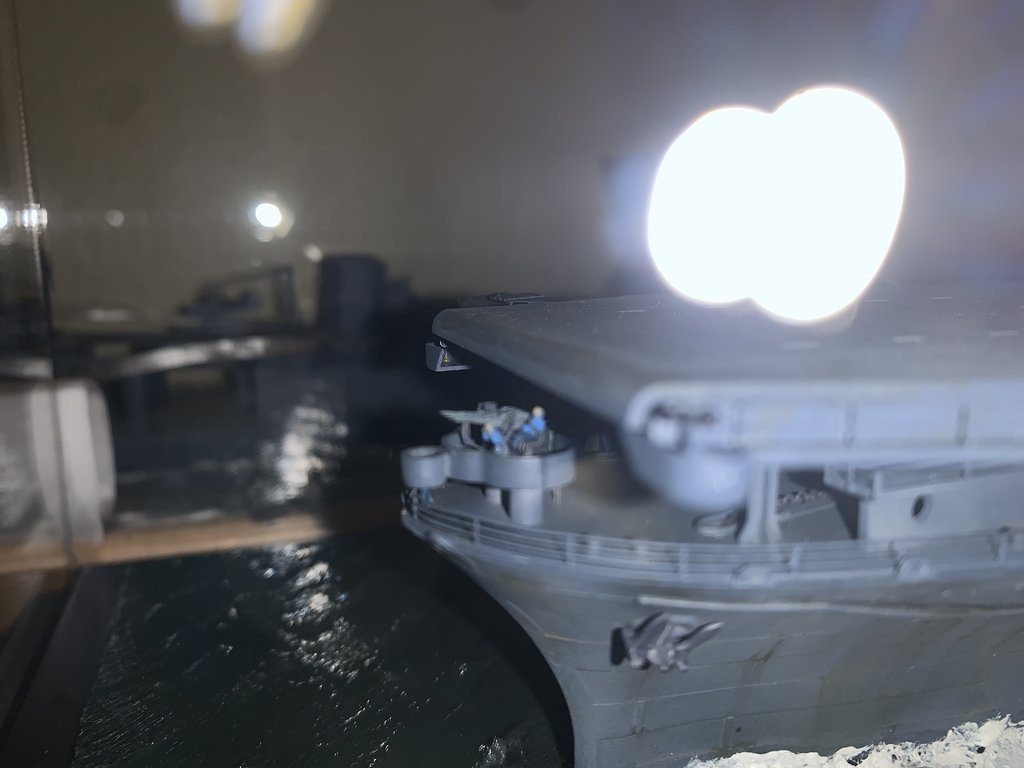
I scratch built a new gun tub for the 1.1 bow mounted gun. I made the walls taller, and the base deck thinner, so overall the gun sits ~1.5 mm lower than the top of the wall compared to the kit gun tub. I also made the base 'legs' out of 2.5 mm diameter sprue, as the kit 'legs' at 3 mm are a bit too thick. Comparing to the photo of the gun mount on the Hornet (posted above), the new mount scratch built tub looks closer to the real thing.
I also installed the catwalk under the front edge of the flight deck. If the gun were much higher, it would interfere with the catwalk. Overall, I think it's a significant improvement over the kit part.
Mike
I scratch built a new gun tub for the 1.1 bow mounted gun. I made the walls taller, and the base deck thinner, so overall the gun sits ~1.5 mm lower than the top of the wall compared to the kit gun tub. I also made the base 'legs' out of 2.5 mm diameter sprue, as the kit 'legs' at 3 mm are a bit too thick. Comparing to the photo of the gun mount on the Hornet (posted above), the new mount scratch built tub looks closer to the real thing.
I also installed the catwalk under the front edge of the flight deck. If the gun were much higher, it would interfere with the catwalk. Overall, I think it's a significant improvement over the kit part.
Mike
- Attachments
-
-
-
MartinJQuinn

- Posts: 8561
- Joined: Tue Jan 11, 2005 1:40 pm
- Location: New Jersey
Re: 1/350 USS Enterprise CV-6
Very nice work on the brass splinter shields. I thought this bow 1.1 on Hornet and Enterprise had no director, however.
Martin
"Tomorrow is the most important thing in life. Comes into us at midnight very clean. It's perfect when it arrives and it puts itself in our hands. It hopes we've learned something from yesterday." John Wayne
Ship Model Gallery
"Tomorrow is the most important thing in life. Comes into us at midnight very clean. It's perfect when it arrives and it puts itself in our hands. It hopes we've learned something from yesterday." John Wayne
Ship Model Gallery
-
taskforce48
- Posts: 1612
- Joined: Mon May 21, 2007 5:49 pm
- Location: The beautiful PNW
Re: 1/350 USS Enterprise CV-6
I can�t prove that Enterprise did or did not have a director, but there is an image from below that shows that added on tub was there.
Great job all around, looks much more the part!
Matt
Great job all around, looks much more the part!
Matt
In the yards right now:
USS Utah AG-16
On Hold
1/350 USS Portland CA-33 1942
1/350 Trumpeter Texas with a twist
USS Utah AG-16
On Hold
1/350 USS Portland CA-33 1942
1/350 Trumpeter Texas with a twist
-
mconnelley
- Posts: 251
- Joined: Sun Feb 07, 2010 8:13 pm
Re: 1/350 USS Enterprise CV-6
Hello:
Here's a photo that I snatched from someone else's build here (sorry, I don't remember whose):

This photo can also be found as photo F-4 in the war history of the Enterprise:
https://www.history.navy.mil/research/l ... -1945.html
The photo seems to show the director position on the front of the gun tub for the Enterprise. The kit has the director position as a little round mini-tub, so I stuck with that interpretation. I agree that the Hornet didn't have this, but it seems that the Enterprise did.
Mike
Here's a photo that I snatched from someone else's build here (sorry, I don't remember whose):
This photo can also be found as photo F-4 in the war history of the Enterprise:
https://www.history.navy.mil/research/l ... -1945.html
The photo seems to show the director position on the front of the gun tub for the Enterprise. The kit has the director position as a little round mini-tub, so I stuck with that interpretation. I agree that the Hornet didn't have this, but it seems that the Enterprise did.
Mike
-
Guest
Re: 1/350 USS Enterprise CV-6
Hello:
I've finished building up the 20 mm guns (yup, all 49 of them). I've made about half of the bases, so I still have that to finish off.
In other news, the airwing needs wings (funny how that works). Here are the 24 wings for the 12 Avengers. I filled in the panel lines on both sides, but kept the line around the aileron. The top row is puttied, whereas the bottom rows have been filed and sanded.
Mike
I've finished building up the 20 mm guns (yup, all 49 of them). I've made about half of the bases, so I still have that to finish off.
In other news, the airwing needs wings (funny how that works). Here are the 24 wings for the 12 Avengers. I filled in the panel lines on both sides, but kept the line around the aileron. The top row is puttied, whereas the bottom rows have been filed and sanded.
Mike
-
mconnelley
- Posts: 251
- Joined: Sun Feb 07, 2010 8:13 pm
Re: 1/350 USS Enterprise CV-6
Hello:
I've built up all 49 of the 20 mm guns. I've made about half of the bases, so I still have that to do. But it's nice to know that AA gun production is nearing an end.
In other news, the airwing is about to get wings. Here are the 24 wings for the 12 Avengers. As with the planes themselves, I'm filling in the panel lines but I left the lines around the ailerons. Next will be primer and paint...and then the 50 wings for the 25 F4Fs
Mike
I've built up all 49 of the 20 mm guns. I've made about half of the bases, so I still have that to do. But it's nice to know that AA gun production is nearing an end.
In other news, the airwing is about to get wings. Here are the 24 wings for the 12 Avengers. As with the planes themselves, I'm filling in the panel lines but I left the lines around the ailerons. Next will be primer and paint...and then the 50 wings for the 25 F4Fs
Mike
- Attachments
-
-
-
mconnelley
- Posts: 251
- Joined: Sun Feb 07, 2010 8:13 pm
Re: 1/350 USS Enterprise CV-6
Hello:
Work on the island started with opening up the doors. The kit has the doors all closed, but photos show that the doors were usually open. I started each door with a 1 mm drill, to remove as much material as I could, then a #11 facto blade and finally a file to straighten out the edges.
Unfortunately, I repeated a mistake of trusting that Trumpeter/Merit/whoever did things correctly. The kit has 3 doors, one on top of each other, on the aft end of the island. However, it seems that the door at the flight deck level shouldn't be there, based on photos and drawings. Since I had just opened up that door, now I had to fill it in. I now have the two upper doors open, and the bottom on filled in. I have also opened up the rest of the doors on the port side of the island.
Speaking of taking away doors, there's a molded on door on the starboard side of the island, sort of in the middle of nowhere. There used to be a platform leading to that door, but by the time depicted by the model, that platform was gone. Rather than have a door to nowhere, I figured that the door would have been removed so I filed off that door.
Mike
Work on the island started with opening up the doors. The kit has the doors all closed, but photos show that the doors were usually open. I started each door with a 1 mm drill, to remove as much material as I could, then a #11 facto blade and finally a file to straighten out the edges.
Unfortunately, I repeated a mistake of trusting that Trumpeter/Merit/whoever did things correctly. The kit has 3 doors, one on top of each other, on the aft end of the island. However, it seems that the door at the flight deck level shouldn't be there, based on photos and drawings. Since I had just opened up that door, now I had to fill it in. I now have the two upper doors open, and the bottom on filled in. I have also opened up the rest of the doors on the port side of the island.
Speaking of taking away doors, there's a molded on door on the starboard side of the island, sort of in the middle of nowhere. There used to be a platform leading to that door, but by the time depicted by the model, that platform was gone. Rather than have a door to nowhere, I figured that the door would have been removed so I filed off that door.
Mike
- Attachments
-
Last edited by mconnelley on Mon Mar 27, 2023 11:17 pm, edited 1 time in total.
-
mconnelley
- Posts: 251
- Joined: Sun Feb 07, 2010 8:13 pm
Re: 1/350 USS Enterprise CV-6
Hello:
Some more work on the wings of the air wing, specifically the 50 wing panels for the 25 F4Fs. Only one side has been puttied...still need to put the other side for all 50.
Mike
Some more work on the wings of the air wing, specifically the 50 wing panels for the 25 F4Fs. Only one side has been puttied...still need to put the other side for all 50.
Mike
- Attachments
-