Page 5 of 10
Re: USS Tecumseh - Canonicus Class ACW Monitor
Posted: Sat Sep 10, 2011 8:28 pm
by Devin
Owen,
I forgot to respond to your email on this until I saw this post. Doh!
I honestly don't know what that device is, but I wouldn't rule out a compass housing. The image you sent me definitely shows the compass in the raised enclosure above the pilot house, but I can only recall seeing a single image of a ship actually using that during the war. What you may be seeing is the usual/alternative arrangement for the compass, in much the same way that a lot of the period and post-war drawings show the extra helm on the turret roof, the rigging for emergency steering, and the emergency tiller hooked up to the rudder. That's just a guess, though.
-Devin
Re: USS Tecumseh - Canonicus Class ACW Monitor
Posted: Sat Sep 10, 2011 11:29 pm
by Roscoe
Owen,
I'm running out of words to describe your model, I've already repeated myself once or twice (or more), but there's only so many words in the dictionary

.
And the only thing I think the turret interior needs is more gunpowder & cannon balls, seriously, it looks fantabulous (add that to the dictionary

)
You know, I remember seeing something like that housing thingy somewhere, I'll check around and see if I can re-find it.
Dean
Re: USS Tecumseh - Canonicus Class ACW Monitor
Posted: Sun Sep 11, 2011 12:55 am
by DrPR
Owen,
Here is a wild guess about the pilot house mechanism. You need two basic things in a pilot house - a way to control the rudder (the helm) and a way to control speed/direction.
What I see in the drawing could be an early version of an engine order telegraph (EOT). It looks like a wheel with a handle on it, and a gear in the center that engages the vertical bar with teeth. Rotating the wheel would raise and lower the vertical bar. As it happens the engineering spaces were directly below the pilot house, so the vertical bar could be attached to a similar wheel below decks to indicate the engine order (direction and speed).
More modern EOTs have handles that rotate around an axis to move a pointer to the desired engine speed/direction. Although they look a lot different the mechanism is essentially the same.
The binnacle may have presented a problem inside the iron pilot house - the mass of iron would surely interfere with the Earth's magnetic field. On more modern ships the binnacle was usually topside, outside the ship's metal structure. Still, it was necessary to adjust the "navigator's balls" on the binnacle to calibrate the magnetic compass to compensate for the ship's interference. Inside the pilot house was a compass repeater slaved to the ship's gyro - that is what we normally steered by. Such a thing didn't exist in the days of the monitors.
Phil
Re: USS Tecumseh - Canonicus Class ACW Monitor
Posted: Sun Sep 11, 2011 6:47 am
by Guest
A hatch?
Re: USS Tecumseh - Canonicus Class ACW Monitor
Posted: Sun Sep 11, 2011 10:58 am
by Roscoe
Owen,
I think Phil is right, an EOT. Here's another pic, although not the Tecumseh, it looks to be the same.

Dean
Re: USS Tecumseh - Canonicus Class ACW Monitor
Posted: Sun Sep 11, 2011 8:36 pm
by Devin
That makes sense. I never thought of it, but there had to be a way to convey speed orders through a hellishly noisy turret.
Re: USS Tecumseh - Canonicus Class ACW Monitor
Posted: Mon Sep 12, 2011 10:20 am
by tea monster
Thank you everyone for all the information, it's really helped. I'm thinking that Phil was right too. I've put in a telegraph that is about the size indicated on the plans. I've also included a speaking tube. I'm still not sure on that serrated-looking vertical thing. I'm thinking that, as Phil said, it's some kind of mechanical regulator, but without knowing really what it looks like, I'd rather err on the side of established design and put something in that people will recognize more readily. so I've left that out till some more info pops up. Again, if anyone can find any info, I'd be grateful! I've followed the plans as to placement and size, but it does look odd compared to other examples I've seen for other vessels. I'm wondering if Ericsson came up with one of his custom wonders for that bit of the monitor.
On a separate note, I've done most of the modelling. There might be some final bits and pieces (I've got to rig the lifeboats), but the major part of the modelling is complete. On to texturing!!
Owen
Re: USS Tecumseh - Canonicus Class ACW Monitor
Posted: Mon Sep 12, 2011 11:29 am
by Roscoe
Looking good... if I were to guess what that serrated-looking vertical thing is, could be each notch was a speed setting on the telegraph, how it was actuated is another thing though, possibly like a ratchet.?
Dean
Re: USS Tecumseh - Canonicus Class ACW Monitor
Posted: Tue Sep 13, 2011 12:15 am
by DrPR
Here are some images from a French monitor plan. It is labeled "Monitors Light Draught Plan General" and "Cherbourg le 20 aoul 1867." The pilot house arrangement is similar to the pictures posted earlier. It appears to have a second conning station below decks with a helm and EOT.
You show a relatively modern EOT in your model, but I doubt that it had such a thing. The monitors were very early steam ships and there were likely many different methods of communicating engine orders in ships of different types. The modern EOT would have evolved later.
I looked for the history of engine order telegraphs and found a little information. A British patent No. 2384 was issued in 1870 to the Chadburn Company which produced EOTs well into the 20th century. The earliest US patent was No. 184,774 "Improvement in Apparatus for Transmitting and Receiving Signals &c," issued in 1876 to a British fellow.
A picture posted earlier appears to show a rack and pinion mechanism. A wheel (not lever) in the pilot house would have a pinion gear at the center. This would engage the rack gear to cause the vertical shaft to move up and down. If the shaft had a similar rack and pinion at the bottom it could rotate a lever or wheel to indicate the engine order. The monitor drawings show a wheel and not a lever in the pilot house, although they really don't show much detail of any sort. I would guess that these early systems just used a simple wheel.
It will be interesting to see if anyone can find a drawing or photograph of a monitor pilot house that actually shows the EOT mechanism.
Phil
Re: USS Tecumseh - Canonicus Class ACW Monitor
Posted: Tue Sep 13, 2011 7:24 am
by mcg
Phil, a wonderful find! And the patent literature search really helps fill in the story.
In the original USS Monitor Ericsson brought control inputs out of the (rotating) turret using square rods running in vertical keyways machined into the turret shaft. In the later monitors, where the turret shaft was fixed, he seems to have stayed with this practice. This is the type of linkage that may be shown in the image Roscoe posted above.
Here is a photo taken underneath the turret of the USS Catskill, showing a couple of outputs. Note the rack and pinion. I think the rack slides up and down and drives the pinion.
This picture appears upside down in "Old Steam Navy," where the author characterizes the quarter pinion as part of an appartus installed in the late 19th century to lift the turret hydraulically. This turret-lifting conjecture is wrong, because the same gear appears in a civil war era photograph of the USS Camanche. So what is it?
It would not be surprising if Ericsson devised direct engine controls for the pilothouse, like those we would expect to find in a locomotive cab. The turret was mounted just ahead of the boilers, so he could have easily fashioned a steam valve control.
There would need to be an additional, strongly leveraged control for the reversing gear. Maybe that's what the handwheel does, via a rack and pinion or a worm drive. By controlling the reversing gear, the handwheel would provide control of both boatspeed and direction. Zero position is stop. Full rotation in one direction is full speed ahead. Full rotation in the other direction is full speed reverse.
http://www.youtube.com/watch?v=VWn8gQ9Ykpk
The front handwheel on this model of the Ericsson engine (the big wheel with the spinner handle) is the reversing gear wheel. The idea would be to remotely actuate or replicate this same handwheel in the pilothouse.
Ericsson used a hand cranked worm drive, bellcranks, and rods sliding in keyways to drive the reversing link for the turrret engine in the original Monitor. Maybe he used a similar system to control, from the pilothouse, the reversing gear for the main engine of the later Monitors. Anyway, there's one more hypothesis.
Michael
Re: USS Tecumseh - Canonicus Class ACW Monitor
Posted: Thu Sep 15, 2011 2:00 am
by DrPR
Michael,
That is a great picture. Clearly, the rack and pinion is driving a shaft exiting to the left of the photo.
Look at the size of the gears and bolts! The size of the wheel in the drawings is pretty large - you would need a large diameter to get the mechanical advantage needed to move all of that mass!
I think the French monitor plans came from this site:
http://www.servicehistorique.sga.defens ... tebato.php
Phil
Re: USS Tecumseh - Canonicus Class ACW Monitor
Posted: Thu Sep 15, 2011 2:19 am
by tea monster
Wow!
I've been looking at the blueprints and the photo. (do you have any more of the interior of the Passaic?)
That does make sense. You can really see the form of the thing and the linkages in the French plans. The one on the American plan seems to be a simplified version of that. It looks like there is some round form behind the wheel on the US plans, like there is a disc behind the wheel (with markings and an arrow that show the setting?). I can see how the wheel for the engine telegraph is off-set and drives the vertical mechanical gear. The only thing I'm not sure of is the form of the top of the housing on the US one. It looks slightly different from the French one, like there is some kind of metal 'hood' over the top of the unit. The French one looks like a more refined version of it. It's much more mechanically 'transparent' as to what goes where though. I'm trying do some sketches to get a viable form together for how the US one is different. When I get something that looks like it would work, I'll post it.
I am tempted to just model the French one. I can see clearly how it works and goes together, it's a lot more detailed than the one on the US plans and it might be more accurate to what was actually built than the US plans as well. I say this as it's possible that the French drew up their plans from an actual set of gear from an existing US Monitor, while the US Plans were done before the ships were constructed in the first place. I'd feel more comfortable getting something that is clearly defined as to what it is for the period, than making up something that MAY be like it was on the original and later winds up to be completely wrong to any vessel of the period.
either way, I'll get something together, in either 2D or 3D and post it up soon.
It looks initially like that brass wheel in the right of the photo might be the same thing as in the pilot house.
I'd like to say a big thank you to of you for helping with this!
Owen
Re: USS Tecumseh - Canonicus Class ACW Monitor
Posted: Thu Sep 15, 2011 8:40 am
by mcg
Same sub-turret apparatus in the USS Camanche. A more proportionate photo.
The pinion is fitted but the rack is not -- or not yet.
The Camanche was, in effect, assembled from a big kit shipped to San Francisco, and several photos show it in the process of assembly. This might account for the missing rack. Another explanation, from "Old Steam Navy" is that the Camanche kit, before it was shipped to California, was cannibalized for replacement parts for Monitors damaged in combat in the East.
The output on the right , picked-off as usual from a vertical slider, is the turret engine reversing control.
The is the Camanche's turret under construction. This photo was taken by Carleton E. Watkins, and appears in Vischer's Pictorial of California, published in 1870. The Henry E. Huntington Library has this book, though I have not seen it. There is a copy for sale on Abebooks for $27,500. Apparently the photographic prints were actually corner mounted into the book. Only a small part of the book treated the Navy. Still, it would be interesting to see. There is a Carleton E. Watkins site. He was in the business of making stereo views. Here is one of the Camanche:
http://www.carletonwatkins.org/views/hi ... 0679bl.htm
It occurs to me that because the USS Camanche was shipped to California for assembly, there might be in California a collection of these documentary photos of this monitor under construction. If so, this could be very helpful in the scholarship and CAD reconstructions we are doing here.
Re: USS Tecumseh - Canonicus Class ACW Monitor
Posted: Fri Sep 16, 2011 12:19 am
by DrPR
A long time back I came across several California historical photo collections on line - don't have any idea where now. I think they were in university libraries.
I wonder if the reversing mechanism was driven by the same rack as the pinion gear? Did the one wheel in the pilot house control both speed and direction?
If anyone wants the full plan for the French monitor send me a personal message or contact me through:
http://www.okieboat.com/Contact%20page.html
It was dated 1867 - that isn't very long after the first US monitors were built. How quickly did the european navies start building monitors? I was also wondering if the plan was for a US monitor. One interesting thing is that the propellers were flat bladed - as was common at the time - and fit into wells that protruded above the main deck because of the very shallow draft. It has two cylindrical sections protruding above the deck where the props are. Did any US monitors have this feature?
Phil
Re: USS Tecumseh - Canonicus Class ACW Monitor
Posted: Fri Sep 16, 2011 8:19 am
by Devin
France and other countries bought several of the U.S. monitors after the war. So, as stated, the plans very well could be for a French update of an older U.S. design.
Almost all of the U.S. monitors had a high/shallow prop well with a removable cover so that the prop could be inspected and/or swapped out without dry-docking the ship. I don't recall any of them actually having the prop proud of the deck when in use, though. Do you have a link to any photos? It would seem to me that leaving the prop so vulnerable to enemy fire would be counter to everything else they did to make sure everything of importance except for the turret was below the waterline. Unless it was one of the Casco class; they did all kinds of weird things to those boats in an attempt to salvage that boondoggle.
Re: USS Tecumseh - Canonicus Class ACW Monitor
Posted: Fri Sep 16, 2011 2:19 pm
by tea monster
Those blueprints look like the American Casco class, which were specially built for shallow-draught operations. The main designer (Ericsson) left the project and the work was completed by someone who, basically, didn't know what they were doing, and the vessels were a complete disaster. According to records, the back deck was awash when she was launched, and that was without armaments or a load of coal!. Hopefully, the French didn't copy the design too closely!
Owen
Re: USS Tecumseh - Canonicus Class ACW Monitor
Posted: Sat Sep 17, 2011 12:41 am
by DrPR
The French plans do look like a Casco class monitor. I found a plan for the USS Nausett on Wikipedia:
http://en.wikipedia.org/wiki/File:Uss_Nausett_1865.jpg
It is almost the same as the French ship.
I was wrong about the cover over the propellers. On closer inspection of the drawing I see it was a soemwhat oval dome instead of like a cylindrical section. And the blades do extend above the main deck slightly.
Phil
Re: USS Tecumseh - Canonicus Class ACW Monitor
Posted: Sat Sep 17, 2011 10:42 am
by tea monster
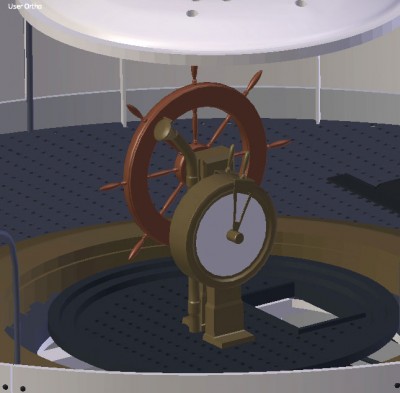
Here is my take on the Helm of the Tecumseh. I've got the basic 'workings' from the French plans (thank you Phil!), but it's got the 'styling' from the US plans and drawings. I've assumed that there is a disk behind the wheel that shows the 'speed' as on several US diagrams I can see that there is something round between the wheel and the background of the illustration. I've not put a compass on there, as I know that there has to be one, but there is no indication of where it is or what it looked like so I think I'm going to leave it, rather that put in something that is wrong. It may be that the compass was held in the hull, if only due to a lack of room in the pilot house!
I managed to find a contemporary drawing, from the Good People at Harper's Weekly. I can't say that it is particularly 'accurate' but it kind of confirms the general arrangement, if nothing else.
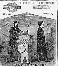
- PILOTHOUSEHARPERS.jpg (35.73 KiB) Viewed 2367 times

Owen
Re: USS Tecumseh - Canonicus Class ACW Monitor
Posted: Sat Sep 17, 2011 4:47 pm
by Devin
Excellent work. That's a very plausible rendition. I wish I'd had some idea of this before I built my Weehawken.
Re: USS Tecumseh - Canonicus Class ACW Monitor
Posted: Sat Sep 17, 2011 5:57 pm
by mcg
Looks excellent, Owen.
Attached is some discussion from the book, "Old Steam Navy" of where the binnacle went in the Passaic class monitors, and apparently in the Canonicus as well.
