Page 1 of 2
Converting Revell's 1/144th scale LSM to LSMR-198
Posted: Sun Dec 27, 2015 11:06 pm
by jcmackay

- A very recognizable still from US Navy footage of LSM(R)s during the Okinawa invasion. Here we have LSM(R)-196, 198, and 199.
Hi everyone,
If you've seen some of my other projects, you won't be surprised that I could not simply build the Revell LSM out of the box. The subject of this build is the USS LSM(R)-198, which was one of the twelve 'Interim LSM(R)s.' The first eight ships (LSM(R)s 188 � 195) fired fin-stabilized 5-inch rockets from manually-loaded rail-type rocket launchers. The remaining four ships of the Interim LSM(R) class (LSM(R)s 196 - 199) fired spin-stabilized rockets from manually-loaded auto-feeding launchers. These ships came about as a result of the Navy's experience early in the island-hopping Pacific war. The Navy realized that during the early stages of an island assault, they needed fire support to bridge the gap between the conclusion of heavy shore bombardment and just prior to the troops hitting the beach. The Navy had achieved good results with LCI's modified to launch rockets, but was looking for increased firepower offered by a larger ship. In 1944 when LSMs began to leave US shipyards, the answer came in the form of LSM hulls converted to be 'rocket ships' or LSM(R)s. So why, you might ask, were hull numbers 188 � 199 referred to as 'Interim' LSM(R)s? Well, the LSMR-401 class with its advanced rocket launcher system was on the drawing boards but not due to reach the fleet until mid-1945, in time for the invasion of Japan. In the interim, though, the Navy was preparing for two upcoming major invasions, Iwo Jima and Okinawa, where rocket ships would be needed. Thus, the 'interim' ships were built and fielded. As it turned out, although the Navy rushed to get the 'interim' ships on line, they arrived too late to support the Iwo Jima invasion. Beginning April Fool's Day, 1 April 1945, the ships provided initial support for the invasion of Okinawa, though. Later, due to scarce resources available to deal with the Kamikaze threat, they were assigned to radar picket station duty. It was during the assignment to radar picket duty that Kamikaze attacks sank three of the Interim LSM(R)s and damaged three others. Following Okinawa, the nine surviving Interim LSM(R)s were sent to Pearl Harbor for conversion into ammo carriers for the planned invasion of Japan.
I recently had the pleasure to attend a reunion of WW2 LSM(R) veterans in Glenview, Ill. It was a joy and an honor to share their company. Although their numbers are rapidly declining, they are making plans for another reunion this coming year. Of the ships represented at the reunion, the shipmates from LSM(R)-198 were the most numerous, which is why I chose this ship as the subject of this conversion.
In the coming weeks, I'll show you my conversion of the Revell kit into the 198. A quick note, though: we are in the process of moving and we still haven't ironed out many details, including internet access. At some point, I expect I'll have to take a short sabbatical.
Thanks for stopping by.
John

Beginning assembly of the hull
Posted: Tue Dec 29, 2015 9:00 am
by jcmackay
Hi everyone,
In today's post, I'll show you the first steps in hull assembly.
I decided to waterline this model. The kit's hull halves have pre-existing inboard grooves that appear to correspond to the beached waterline of an LSM. I began by assembling the two hull halves and cutting out the lower hull:

- The hull is essentially 4 pieces: port and starboard halves, the lower stern, and fantail bulkhead. Since the model would be a waterline version, I didn't need to install the lower stern section. The kit has two athwartships stiffeners that will perform the important function of keeping the hull halves in alignment once the lower hull is removed.
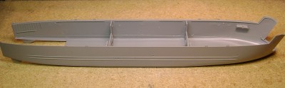
- Here's another view of the hull halves. In 2016, Revell Germany will be issuing a kit of the later-war LSM, presumably in Bundesmarine markings. While that hull will give modelers more choice in modeling later-war LSMs, the foc'sle profile of the early LSM is more appropriate for a model of an interim LSM(R).

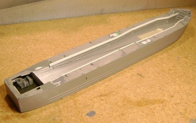
- Here's the hull after cutting the bottom out of the hull. To start, I cut along the molded-in grooves. This will have to be altered later.
John
Hull assembly and compartmentation
Posted: Sun Jan 17, 2016 1:45 pm
by jcmackay
Hi everyone,
We have completed our move to new digs, so now I can resume describing this conversion. Although we were without internet access at our new home for only about 10 days, it seemed like an eternity!
Today, I'll continue the topic of hull assembly and show the start of the stern anchor compartment:

- Since the model will be waterline, I installed some cross-bracing of .060 inch styrene sheet and .060 x .125 inch styrene strips so that I could secure the model to the base.
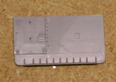
- Revell chose to mold the fantail bulkhead in two pieces; the portion around the stern anchor stand is a separate piece. Although Revell didn't announce it at the time of their release of the early LSM, they planned to release both an early and a late LSM. The stern anchor stand was changed on later LSMs, necessitating a way to incorporate this difference in the two kits. Here's the two pieces assembled. I've also filed down the ladder rungs and drilled new holes for brass wire.

- A shot of the basic hull assembled. Here's something to be cautious of: it is possible to install the tank well deck too far aft. If you do, the stern bulkhead will not mount flush against the sides of the hull.

- On Interim LSMRs, the area that was formerly the hold was divided up into various compartments including rocket component stowage and rocket assembly rooms. One of the new compartments included the room below the fantail-mounted 5 inch 38 gun house. Although it won't be readily visible, I'll install the aft bulkhead for this compartment. To accommodate the new bulkhead, it is necessary to trim .030 off the aft end of the port longitudinal bulkhead.
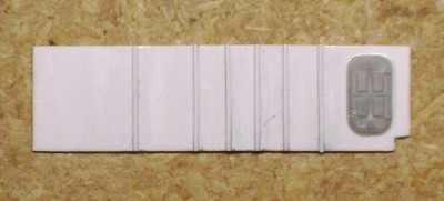
- The new athwartships bulkhead was fabricated from .030 inch styrene with frames of .020 x .020 inch styrene strips. The new compartment bulkhead did away with the port side watertight door and this door was scavenged for the new starboard side WT door.

- Here's the new bulkhead installed.

- And a shot of the compartment in primer.
John
Re: Converting Revell's 1/144th scale LSM to LSMR-198
Posted: Sun Jan 17, 2016 3:06 pm
by Goodwood
Looking good so far, John!
Should be interesting to see how you scratch-build the rocket launchers, and seeing just how many these things carried...I've seen footage of them in action, but never a proper picture of what one of these rocket-boats looked like. Just imagine what it would've been like if the British at Fort McHenry had had one of them in their fleet!
Installing the main deck
Posted: Thu Jan 21, 2016 8:48 pm
by jcmackay
Hi everyone,
A note of thanks to Sean (�Goodwood�), who wrote,
Goodwood wrote:Should be interesting to see how you scratch-build the rocket launchers, and seeing just how many these things carried...I've seen footage of them in action, but never a proper picture of what one of these rocket-boats looked like...
Indeed, the launchers will be the biggest challenge of this build. LSMR-198 had 85 MK 51 launchers on her deck, which will be a challenge to build. I've been working on those already, but they will take the most amount of time to complete. More on that later. Thanks for your comments!

Today's topic is installation of the main deck. First, though, a look at the stern anchor winch room after painting:

- Bulkheads were painted white, the deck was black green, and the winch is neutral gray. The winch is not yet complete in this photo.
Next, deck work:

- The deck on the fantail has to be modified to incorporate the plan of the raised deck for the 5 inch gun. This view shows the deck as it came in the kit.

- Here's the deck after correcting the outline of the raised deck and filling in the base of the port aft 20 mm gun tub. I'm not going to use the kit's gun tubs: for starters, the wall thickness is not correct for scale. Also, the aft gun tubs were moved forward on the interim LSMRs.
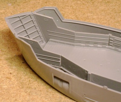
- The bow has to be cut down for the focsle 40mm gun installation. Here is a view of the kit's bow before cutting.

- The bow was cut off level with the top of the bow doors.

- The forward sections of the deck are installed. Once again, I'm not using the kit's gun tubs, so I've filled the deck openings with .040 inch styrene.

- I've completed installing the deck. Transitions between the fantail portion and the remaining deck are kinda rough, so they've been filled with Green Putty. The winch has been assembled and a length of thread has been wound on the winch wire spool for the stern anchor.
John
Installing the raised deck
Posted: Sat Jan 30, 2016 12:23 am
by jcmackay
Hi everyone,
Today, I'll show you the installation of the raised deck. On the 'second flight' ships of the Interim LSMR Class (hull numbers 196 � 199), the deck over the tank well was raised 6 inches above the level of the original LSM hull main deck. In contrast, the deck on the first flight ships (hull numbers 188 � 195) was at the same level as the surrounding original main deck. Here's a look at how I did that:
- I used .060 x .125 inch styrene strips glued to the tank well bulkheads to provide a raised surface about .030 inch above the level of the existing deck.

- Cross braces of styrene were added to give rigidity and additional mounting surface for the deck. On the fantail, the deck was raised 12 inches, which is why the styrene strips don't extend all the way aft.

- I used some .125 x .125 inch and .156 x .156 inch styrene for the braces � they just happened to be what I had on hand!
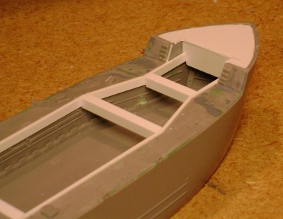
- Before I attached the raised deck, I installed the focsle deck. It would be easier to fill/file/sand the edges before the deck interferes.

- Here's the focsle deck with a quick coat of gray primer. Also, I've filled the bow door gaps. These will get more attention later.

- At last, a deck of .010 inch styrene is installed! The deck is about .040 inch above the surrounding main deck, or 6 inches in scale. Once again, acrylic gel medium was applied over a wood base painted with acrylic Payne's Grey.
John
Re: Converting Revell's 1/144th scale LSM to LSMR-198
Posted: Sat Jan 30, 2016 2:41 am
by Goodwood
Your scratch-building skills and how you describe what it is you're doing really highlight the level of research you put into these conversion builds, John. Keep up the excellent work!
Bow work and installing gun tubs
Posted: Sat Feb 06, 2016 11:47 am
by jcmackay
Hi everyone,
Thank you, Sean (Goodwood), for posting your kind comments. I always look forward to your feedback!
Today's post will describe work on the bow and installing the gun tubs or 'gun shields.' First, let's look at work on the bow:

- After the LSM bow doors were welded shut on the Interim LSMRs, the gaps were covered over with sheet steel. Here, I've replicated that with strips of .005 inch styrene.

- Here's another bow-on shot. All mating seams on the doors were covered with styrene.
And on to installing gun tubs:
- I guess I'm kinda picky, but I didn't like the thickness of the kit's gun tubs. They scale out to almost 6 inches thick, whereas the actual shields were .25 inch thick. I installed gun tubs of brass .005 inch sheet, attached with CA.
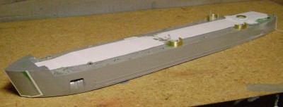
- Another view. You'll also notice the raised deck for the fantail-mounted 5 inch 38. This was 12 inches higher than the surrounding main deck. I built a frame of .060 x .100 inch styrene and topped it with .010 inch styrene sheet and then positioned to the correct height. The base ring for the mount was made of styrene bits added to a section of round styrene cut from a spare fuel tank from a 1/32nd Revell Ki-43 Oscar!
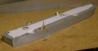
- A view from aft starboard. You can see the first step in installing the stern anchor platform in this shot. The kit represents an early LSM; on the early LSMs, the platform was lower. This configuration was changed on later LSMs. It is relatively easy to modify this on the kit, though. More on that later. I've also added a coaming of .005 inch styrene around the aft starboard ladder opening. This is not represented on the kit. I've also begun adding topside details, such as the smoke stack and bitts.
John
Conn superstructure, more topside details, and anchor platfo
Posted: Sat Feb 13, 2016 11:50 am
by jcmackay
Hi everyone,
Today, I'll show you some work on the conn superstructure, topside detailing, and the stern anchor platform:

- The conn superstructure is a complicated assembly. This is the lower section. On LSMs, there was a railing that ran forward to aft on the inboard side. I've glued scrap styrene into the mounting holes for the railing since the railing won't be installed.

- Here is the stern anchor platform. It can be used as is, but will have to be repositioned to the level of the main deck.

- Here's the beginnings of the 40mm gun tubs. The tubs began as 0.010 inch styrene. A strip of .040 inch styrene was mounted along the inner wall of the tubs to replicate 40mm ammo storage. The one on the left will be mounted on the focsle, the one on the right will go on an elevated frame just forward of the conn.

- Canvas covers were installed over the 40mm ammo storage. Here, I've replicated the canvas with tissue installed with white glue.

- The focsle 40mm tub is installed. I've also installed the topside watertight hatches along the centerline forward-to-aft and the topside hatch aft of the gun mount. The centerline hatches led to the rocket storage and assembly rooms below. These were scratchbuilt of styrene sheet and stretched sprue for the hinges and dogs. These hatches did not have handwheels.

- Other topside details such as ventilators and focsle ladders have been installed. The ladders are a bit on the thick side, but lacking an alternative, I decided to use them anyway.

- The only significant difference between the kit stern anchor platform configuration and the configuration on later LSMs is that the platform was mounted even with the main deck on later ships. The kit accurately replicates the slight upward angle of the platform. New holes were drilled and the associated support struts from the kit were installed.
John
More work on topside details
Posted: Fri Feb 26, 2016 11:50 pm
by jcmackay
Re: Converting Revell's 1/144th scale LSM to LSMR-198
Posted: Sat Feb 27, 2016 9:06 am
by Goodwood
Excellently-executed intricate work, John! Looking forward to more updates...and the dreaded rocket rails!

The hull in primer
Posted: Mon Feb 29, 2016 11:19 pm
by jcmackay
Hi everyone,
Today, we'll have a look at the hull in primer.
First, allow me to thank Sean (Goodwood) for his kind words.
I know you're really curious about the launchers. I've been mulling over the dreaded launchers for a while and here's my plan:
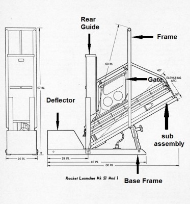
- There are 6 major parts of the launcher: (1) the base frame on which (2) the deflector is mounted, (3) the gate, (4) rear guide, (5) the frame, and the attached launcher (6) sub-assembly. The launchers will be constructed using resin castings for the base frame and deflector, styrene pieces for the gate and rear guide, and PE for the frame and attached sub-assembly. I've already cast the base frame/deflectors and have been constructing the gate/rear guides. Currently, I'm trying to come up with a satisfactory drawing of the frame/sub-assembly that I can submit to a PE shop to make a batch up for me. (I'm not going to try making the PE myself � it would be a steep learning curve.) Any suggestions are welcome! And, of course, photos to follow as I make some progress.
Here's how the hull looks in primer:

- A view from port. I've started building a gun house for the fantail 5 inch 38, but I think I am going to purchase one from an online vendor. More on that later.

- Here's a look from starboard. I won't be permanently installing the conn superstructure until much later because it will be fragile and too much work remains to be done on the hull first.
John
Measure 31 Design 10L camouflage
Posted: Sun Mar 13, 2016 12:50 pm
by jcmackay
Re: Converting Revell's 1/144th scale LSM to LSMR-198
Posted: Sun Mar 13, 2016 1:22 pm
by Goodwood
Excellent basic paint job, John! I wonder if perhaps that gray should be just a bit darker even if you intend to weather the ship...again not a true black, but not quite as light as what you've got now. As it stands, in that light it more closely resembles RLM 81, which was a dark brown-gray used on late-war German aircraft.
Just my two kopecks, I'm sure it looks better in person.

5 inch 38 Gun House
Posted: Sun May 01, 2016 12:38 am
by jcmackay
Hi everyone,
Boy, it has been a long time! We've spent the last couple months recovering from moving and I still don't have a decent place for my hobby. We'll be going to an LSMR reunion in June, so I'm going to try to make some progress on this project so I can display it at the reunion.
A quick note of thanks to Sean (Goodwood) for his previous comments. In the future, I intend to weather the hull so that the current gray appearance better replicates weathered black, so it's not time to despair yet!

I've been tinkering with drawings for the PE for launchers, but my first drawings were too complicated for the size of the PE, so I'm working on a different approach. In the meantime, I may scratchbuild tarpaulin-covered launchers for the time being. In service, the launchers were covered except when getting ready to launch. The launcher electrical connections were extremely sensitive and temperamental, and the covers helped to minimize misfires.
The topic of this update is the 5 inch 38 gun house, or 'turret.' As I mentioned before, I decided to order a 'printed' turret in hopes that it would save me some time and effort. The turret came from Model Monkey; here's a look:

- The turret is the 'early' style or 'single knuckle' turret and comes in two pieces, the turret and the gun barrel. My scratchbuilt turret is of course on the right. Although the piece comes with crisp panel details and frame detailing on the bottom of the turret, the rest of the surface is pretty rough, which will take some time to clean up. Time will tell if taking this route proves to be the more expedient path.
John
Re: Converting Revell's 1/144th scale LSM to LSMR-198
Posted: Thu May 12, 2016 10:00 pm
by dhenning
Looking great! What are your plans for the 20mm's? I have the kit buried somewhere in the stash, but might consider picking up another one if the 20mm's are good. I have a project where I need two and could probably use some more when I build my 1/144 Fletcher. What is your opinion of the ones provided with the LSM kit?
Thanks for the update!
David
Report on the 20mm guns
Posted: Sat May 14, 2016 3:47 pm
by jcmackay
Hi David,
I'm working on dressing up the 20mm guns now. With a little work, they can look presentable. I'd recommend doing something about the barrel, which is about 4.5 inches in diameter in 1/144th scale. What I'm doing is cutting off about .125 inches of the barrel, drilling a hole in the exposed stub, and using CA to install a piece of .015 piano wire, which gives the guns are better appearance. One other thing I have done is use a half-round jeweler's file to dress up the shoulder rests, which look like T-blobs as molded. Of course, the guns are very small, so it is slow work. However, if you are building a LSM(R), which only had four 20mm guns, you'll have leftover 20mm guns from the LSM kit that might come in handy in case you're ham-handed!
One other thing to be aware of is that the kit's guns are indeed the early version, without the Mk 14 gun sight. LSM(R)s had the Mk 14 sight; I'll probably fashion them out of styrene.
Thanks for following along and posting your kind words!
John
Update on the 5 inch 38 turret
Posted: Sat Jun 04, 2016 12:04 am
by jcmackay
Re: Converting Revell's 1/144th scale LSM to LSMR-198
Posted: Sat Aug 20, 2016 12:10 am
by dhenning
John,
Hope you are all settled into the new home and back to modeling. During a recent trip, I read the book "The Heart of Hell" by Mitch Wise. It is the story of the LCI(G)-449 leading up to Iwo Jima. Highly recommended. I've decided to build one of my Lindberg LCIs as a gunboat and will use your LCI build to assist.
Have you made progress on the rocket launchers for your LSM build? Are you still pursuing photo-etch? If so, could a fellow modeler get in the loop to purchase 10 for an LCI(G)? I know that you are modeling a Mk 51 launcher and the LCI's used Mk 7, but I think the difference at this scale would be negligible.
Have you considered getting one of the 3d designers on the forum to print these out instead of photoetch?
Hope all is well and looking forward to following your builds,
David Henning
Re: Converting Revell's 1/144th scale LSM to LSMR-198
Posted: Sat Aug 20, 2016 12:19 pm
by ModelMonkey
Hi John,
Just saw your post and was surprised and disappointed by the quality of the 3D-printed 5" mount you received. This is not the normal quality of Frosted Detail product printed by Shapeways. You might consider contacting Shapeways customer support and sending them photos of the mount you received. Shapeways may offer you a replacement.
