Waterlining Lindberg's LCI(L)-78 kit

Moderators: BB62vet, MartinJQuinn, JIM BAUMANN, Jon, Dan K

jcmackay
Posts: 413
Joined: Mon Sep 06, 2010 9:33 pm
Location: Port Orchard, Wa

Waterlining Lindberg's LCI(L)-78 kit

Post by jcmackay »

Hi everyone,

No, I didn't mislabel this thread; I'm not going to 'deep six' the Lindberg LCI. If you've visited my previous thread about building the LCI-30, you might have seen that one of the visitors brought up the suggestion of a waterlined LCI. I decided I'd give it a shot.

As a recap from my previous thread, the Lindberg LCI has a number of serious flaws that need to be fixed if one wishes to have a fairly representative example of an LCI. Those flaws make waterlining this kit a bit more challenging.

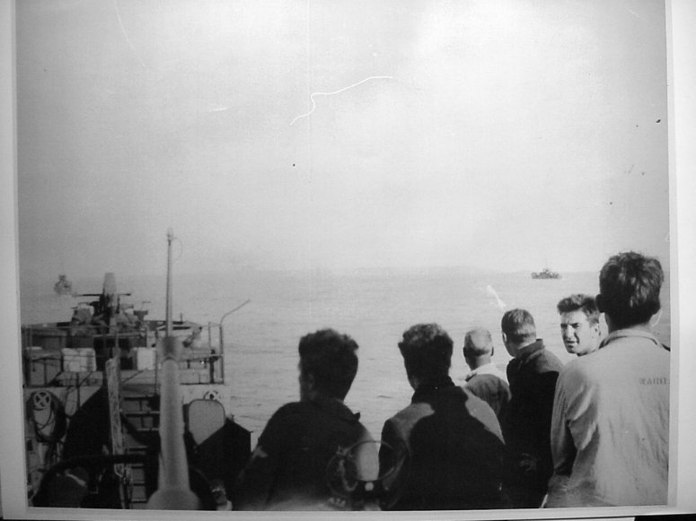
My inspiration for this kit is the following photo of the LCI(L)-361 along with LCI-30 unloading troops during the invasion of New Guinea.
inspiration.jpg
I haven�t decided yet which ship to depict with this model. However, needless to say, it won�t be the LCI(L)-78, because of the mere fact that the -78 was an early square-conn ship, while the kit represents a later round-conn, side-ramp ship. I am torn between finishing it in a single overall color like many of the ships in the Pacific, or applying a camouflage scheme. But I�ll cross that bridge later; I don�t have to make the decision quite yet.

The hull requires a lot of work to make it accurate, but I don�t want to rehash what I�ve previously written about in my LCI-30 thread. I�m going to try to keep the description of the hull modifications to a minimum and refer you to my previous thread on the LCI-30 for additional detail.

As with the LCI-30 project, the bow of the Lindberg kit is not correct, so I began by removing the bow. Before proceeding, I added gunwale detail with styrene strips:
hull halves.jpg
To correct fantail shape and hull dimensions, I removed material along the hull seams and baseline to achieve the correct dimensions and trapezoidal shape of the fantail:
fantail.jpg
hull halves 2.jpg
With a little bit of .060 inch styrene and a generous amount of liquid cement located in strategic places, the hull comes together:
assembly step 1.jpg
assembly step 2.jpg
When this kit was released shortly after the earth cooled, it was motorized.  The residual guides for the motor bulkhead provide a convenient place for a strengthening bulkhead of .060 inch styrene
When this kit was released shortly after the earth cooled, it was motorized. The residual guides for the motor bulkhead provide a convenient place for a strengthening bulkhead of .060 inch styrene
In the next update, I�ll show you how I did the actual waterlining.

John :wave_1:
Last edited by jcmackay on Thu May 25, 2017 8:49 am, edited 1 time in total.
jcmackay
Posts: 413
Joined: Mon Sep 06, 2010 9:33 pm
Location: Port Orchard, Wa

The hull is waterlined

Post by jcmackay »

Hi everyone,

Today, I'll show you the waterlined hull.

First, I began by preparing the center deck section for installation.
Styrene tabs were added to help align and support the deck joint.
Next, installation of the center deck began.
The green putty on the starboard sponson hides the dip that seems to be present on every molding of the LIndberg LCI hull
Then, after finishing the center deck installation, the hull was cut.
I studied several photos to determine how the ships sat in the water when beached to land troops and then made the cuts. I got a little crazy with the knife on the aft starboard hull, but no worries; the scar can be filled and sanded.
The Lindberg bow is wrong, so before I go too far, I have to do some work on the bow.
As I mentioned in the LCI-30 thread, the LCI bow had some distinctive lines.  I've cut two pieces of styrene for the start of correcting the shape of the sides of the bow.
As I mentioned in the LCI-30 thread, the LCI bow had some distinctive lines. I've cut two pieces of styrene for the start of correcting the shape of the sides of the bow.
Here, the styrene pieces are installed on the bow.
The gaps in the gunwales near the focsle are door openings.  I've chosen to depict them as open.
The gaps in the gunwales near the focsle are door openings. I've chosen to depict them as open.
Once the frame for the bow had been installed, I cut then attach the hull to a sheet styrene base.
The styrene base is .080 inch.  With all the modifications to the hull, I wanted to be sure that the hull would not flex or warp, and would provide a secure surface for attaching to the display base.  I reinforced the joint between the inboard hull edges and the styrene base with 100 x .100 inch styrene strip.
The styrene base is .080 inch. With all the modifications to the hull, I wanted to be sure that the hull would not flex or warp, and would provide a secure surface for attaching to the display base. I reinforced the joint between the inboard hull edges and the styrene base with 100 x .100 inch styrene strip.
Next time, I'll show you the cleanup of the base and construction of the new bow.

John :wave_1:
jcmackay
Posts: 413
Joined: Mon Sep 06, 2010 9:33 pm
Location: Port Orchard, Wa

Cleaning up the waterline, building the bow

Post by jcmackay »

Hi everyone,

Today�s update is about cleanup of the base and building the new bow.
I chose to mount the hull on top of the base to assure the base remained flat and the hull would not flex.  This made cleaning up the base along the waterline a little trickier because one must exercise more caution when cleaning up the seam between the hull and base.
I chose to mount the hull on top of the base to assure the base remained flat and the hull would not flex. This made cleaning up the base along the waterline a little trickier because one must exercise more caution when cleaning up the seam between the hull and base.
Here�s a closeup of the new bow ready to be sheeted in styrene.
The hull sheeting is almost complete.
Closeup of the new bow. The distinctive seam along the hull chine was replicated by installing a strip of .040 x .040 inch styrene.
After the bow sheeting was finished, it was time to cleanup the various seams with green putty.
Closeup of the new bow after cleanup.  I checked some of the joints by painting with primer.  Then, corrected with green putty and sanded.
Closeup of the new bow after cleanup. I checked some of the joints by painting with primer. Then, corrected with green putty and sanded.
The superstructure deck and forward and aft bulkheads have been installed.  The seams on the Lindberg kit are pretty rough as built out of the box, but with all the mods I made to the hull, they need a bit more attention.
The superstructure deck and forward and aft bulkheads have been installed. The seams on the Lindberg kit are pretty rough as built out of the box, but with all the mods I made to the hull, they need a bit more attention.

John :wave_1:
jcmackay
Posts: 413
Joined: Mon Sep 06, 2010 9:33 pm
Location: Port Orchard, Wa

Deckhouses

Post by jcmackay »

Hi everyone,

LCI-351 class ships had three entries on the main deck via what I am going to call �deck houses.� I don�t know if that is the proper term for them; perhaps one of our readers can correct me. If you look close at drawings and photos, you�ll notice that the deck houses in the kit are mostly wrong. Today, I�ll show you the rework of the deck houses.
To give a bit of perspective, here is what the original superstructure deck looked like.  On forward and aft ends, it has extensions for the deck houses, which are the wrong shape.
To give a bit of perspective, here is what the original superstructure deck looked like. On forward and aft ends, it has extensions for the deck houses, which are the wrong shape.
For example, this is the superstructure forward deckhouse on the LCI-713.  Although it is not the clearest view, you can see the deck house sides are not straight, but take a couple of jogs.
For example, this is the superstructure forward deckhouse on the LCI-713. Although it is not the clearest view, you can see the deck house sides are not straight, but take a couple of jogs.
The kit�s focsle deck house is the wrong shape.  I�ve used the superstructure forward deckhouse for the focsle deckhouse because it requires little rework. Are you confused yet?   Here�s a view of the slightly reworked deckhouse that will be installed at the aft end of the focsle.  The styrene on top takes the place of the deck extension piece in the kit. I made the steps on this ladder using angle styrene, but for the rest, I�ll make the steps out of .010 x .040 inch styrene.
The kit�s focsle deck house is the wrong shape. I�ve used the superstructure forward deckhouse for the focsle deckhouse because it requires little rework. Are you confused yet? Here�s a view of the slightly reworked deckhouse that will be installed at the aft end of the focsle. The styrene on top takes the place of the deck extension piece in the kit. I made the steps on this ladder using angle styrene, but for the rest, I�ll make the steps out of .010 x .040 inch styrene.
Here�s a shot of the focsle deck house test-fitted.   Notice I�ve cut the door openings.  Eventually, I will add troops to will depict an island landing, inspired by the photo I posted at the start.
Here�s a shot of the focsle deck house test-fitted. Notice I�ve cut the door openings. Eventually, I will add troops to will depict an island landing, inspired by the photo I posted at the start.
Here�s a view of the deck above the superstructure forward deckhouse.  I�ve modified it with a couple of additional angles.
Here�s a view of the deck above the superstructure forward deckhouse. I�ve modified it with a couple of additional angles.
Here�s a view of the superstructure deckhouses.  I installed new bulkheads of styrene.  Yeah, I know they look pretty ugly, with all that putty; I ended up having to use too much putty because of poor fit of the pieces I installed, as you can see in the photos.  I should�ve taken the additional time to ensure a good fit of the styrene bulkheads; it would�ve saved time cleaning up the putty.   Oh well, another learning point.
Here�s a view of the superstructure deckhouses. I installed new bulkheads of styrene. Yeah, I know they look pretty ugly, with all that putty; I ended up having to use too much putty because of poor fit of the pieces I installed, as you can see in the photos. I should�ve taken the additional time to ensure a good fit of the styrene bulkheads; it would�ve saved time cleaning up the putty. Oh well, another learning point.
John :wave_1:
jcmackay
Posts: 413
Joined: Mon Sep 06, 2010 9:33 pm
Location: Port Orchard, Wa

Deckhouse and superstructure seam cleanup

Post by jcmackay »

Hi everyone,

Today, some cleanup work on the deck houses and superstructure.
The deckhouses and superstructure seams have cleaned up nicely, although I should�ve used styrene for the deckhouse bulkheads.
Another view.
Another view.
Closeup of the focsle deckhouse.  I painted the inside of the doorway with flat black because the model will be displayed with the doors open.
Closeup of the focsle deckhouse. I painted the inside of the doorway with flat black because the model will be displayed with the doors open.
John :wave_1:
User avatar
dhenning
Posts: 352
Joined: Sat Oct 05, 2013 1:32 pm

Re: Waterlining Lindberg's LCI(L)-78 kit

Post by dhenning »

John,
Wow-3 builds going on at the same time! Impressive! I finished up my Italeri PT-109 and am looking for my next project. Timing is perfect, so I may just start on the LCI(G) conversion. I'm a little confused on the bow changes-were you able to find cross-sections/frames to guide you or are you doing it from just a side plan view?

Not sure what I will do on the Mk. 7 rocket launcers-might stick with builder a shape out of styrene and covering it up with a tarp for most of them and leave a few exposed.

What did you think of the 1/160 20mm from Shapeways?

David
jcmackay
Posts: 413
Joined: Mon Sep 06, 2010 9:33 pm
Location: Port Orchard, Wa

Re: Waterlining Lindberg's LCI(L)-78 kit

Post by jcmackay »

Hi David,
Thanks for the note and the kind words. :thanks: :thanks: In response to your question about the cross-sections, I have some drawings that I have been working from. But of course, I also relied on photos to try to get it as close as possible. I also made a mold of the bow, hoping to have that to fall back on, should I decide to build another.

With regard to the Shapeways 1/160th 20mm's, I think they are very nice. Currently, though, Shapeways only offers 20mm guns with a modified splinter shield. The vendor was very responsive to my request to resize the 20mm's to 1/160th, but unfortunately, he didn't recognize that he was working off an earlier project for an Iowa Class battleship, with the splinter shields notched. It is barely noticeable and there are examples of LCIs that had the same mod. I hope to show you what they look like soon.

John :wave_1:
User avatar
dhenning
Posts: 352
Joined: Sat Oct 05, 2013 1:32 pm

Re: Waterlining Lindberg's LCI(L)-78 kit

Post by dhenning »

Starting my LCI(G)-449 as well. Needless to say, have been looking at all of your photos and posts for the LCI-30 build, the 691 class build, and this one. Won't be going as far as you on the bow. I filled in the stem with thick superglue and started aggressive reshaping with files and sanding sticks. I have a shape that I am happy with. Added the .030" sq. stock for the bottom chine. Waiting on my Shapeways order of the 1/160 20mm mounts, 40mm Bofors, watertight doors, and ready service lockers (doors and lockers kindly rescaled to 1/160 by Steve "Model Monkey". Waiting anxiously for more info on your build!

David
jcmackay
Posts: 413
Joined: Mon Sep 06, 2010 9:33 pm
Location: Port Orchard, Wa

Trial and error with gun tubs

Post by jcmackay »

Hi everyone,

Thank you, David, for posting your comments:
dhenning wrote:Starting my LCI(G)-449 as well. Needless to say, have been looking at all of your photos and posts for the LCI-30 build, the 691 class build, and this one. Won't be going as far as you on the bow. I filled in the stem with thick superglue and started aggressive reshaping with files and sanding sticks. I have a shape that I am happy with. Added the .030" sq. stock for the bottom chine. Waiting on my Shapeways order of the 1/160 20mm mounts, 40mm Bofors, watertight doors, and ready service lockers (doors and lockers kindly rescaled to 1/160 by Steve "Model Monkey". Waiting anxiously for more info on your build!
That's great to hear you're starting your LCI(G) and I hope you'll be posting some photos on MW soon! I am especially interested to see what you do with the bow and the results of your reshaping of the stern. I haven't ordered the lockers and doors as you have, yet, but I was going to get around to that eventually. Keep us posted! :thanks:

Summer is the time for military reunions and my schedule is very busy with those, so the work on the models has slacked off. I'm also trying to finish up some commission builds, too, but David guilted me with his comments into posting an update. :heh:

Today, I'll show you the trial and error installation of gun tubs:
I thought it would be easier to use .010 inch styrene for the gun tubs.  After all, styrene is easier to cut and much easier to attach to styrene.  However, it didn't work out so well; I couldn't get the tubs to be consistent.  After a bit, I just removed them altogether and decided to go with brass.  Also, you can see that I filled in where I had previously drilled out the port side portholes.  The model has these molded in the wrong location.
I thought it would be easier to use .010 inch styrene for the gun tubs. After all, styrene is easier to cut and much easier to attach to styrene. However, it didn't work out so well; I couldn't get the tubs to be consistent. After a bit, I just removed them altogether and decided to go with brass. Also, you can see that I filled in where I had previously drilled out the port side portholes. The model has these molded in the wrong location.
Here's a view of the brass gun tubs.  I had to attach the .005 inch brass tubs with CA, but of course, once I'd shaped them to the way I wanted them, they didn't unbend.  I haven't installed the focsle gun tub, yet, because I need to get rid of the huge locator hole.
Here's a view of the brass gun tubs. I had to attach the .005 inch brass tubs with CA, but of course, once I'd shaped them to the way I wanted them, they didn't unbend. I haven't installed the focsle gun tub, yet, because I need to get rid of the huge locator hole.
John :wave_1:
Last edited by jcmackay on Mon Jun 26, 2017 7:53 pm, edited 1 time in total.
jcmackay
Posts: 413
Joined: Mon Sep 06, 2010 9:33 pm
Location: Port Orchard, Wa

Bitts and pieces

Post by jcmackay »

Hi everyone,

A quick update on some work since the last post.

I�ve installed the brass focsle gun tub and begun installing the bitts.
The bitts were made from .010 x .060 inch styrene strips and .040 styrene rod.


John :wave_1:
jcmackay
Posts: 413
Joined: Mon Sep 06, 2010 9:33 pm
Location: Port Orchard, Wa

New conn

Post by jcmackay »

Hi everyone,

The conn superstructure on the Lindberg kit is terrible: as can be seen in photos and drawings, LCI conns were round, but the kit has flat sides port and starboard around the watertight door detailing. LCI conns were open to the elements, which resulted in many ships being fitted with an awning to shield the bridge watchstanders from the elements. The top of the kit�s conn is a flat, solid piece that covers what would have been the open conn. I suppose I could have carved and filled the kit conn to make it correct, but I decided to scratchbuild a new one. I�ll show you the start of that today.
The shell of the conn was made from .020 inch styrene, with .040 inch decks.  I aligned the seam of the conn with where the aft door will be located.  The black marks are alignment marks for the portholes.  I capped the conn on the top with a piece of .010 inch styrene.  This would become the sill of the venturi.  Then, I removed the excess styrene material inboard to open up the conn.  Next, I installed venturi stand-off brackets of .015 x .040 styrene.  Finally, the venturi face of .010 x .080 inch styrene was attached.
The shell of the conn was made from .020 inch styrene, with .040 inch decks. I aligned the seam of the conn with where the aft door will be located. The black marks are alignment marks for the portholes. I capped the conn on the top with a piece of .010 inch styrene. This would become the sill of the venturi. Then, I removed the excess styrene material inboard to open up the conn. Next, I installed venturi stand-off brackets of .015 x .040 styrene. Finally, the venturi face of .010 x .080 inch styrene was attached.
I removed the ladder deck house from the kit�s conn and attached it to the new conn.
John :wave_1:
jcmackay
Posts: 413
Joined: Mon Sep 06, 2010 9:33 pm
Location: Port Orchard, Wa

Lifeline Stanchions

Post by jcmackay »

Hi everyone,

Topic of today's update: a bit of work on the conn and beginning to install the lifeline stanchions.
I drilled out the portholes on the conn and test-fitted the mast.
Stanchions are .015 inch piano wire installed with CA.
Eventually, I'll use thread to replicate the lifelines, just as I did on my previous model of the LCI(L)-30.  It may be a bit more work than PE, but I like the appearance better.
Eventually, I'll use thread to replicate the lifelines, just as I did on my previous model of the LCI(L)-30. It may be a bit more work than PE, but I like the appearance better.


John :wave_1:
User avatar
dhenning
Posts: 352
Joined: Sat Oct 05, 2013 1:32 pm

Re: Waterlining Lindberg's LCI(L)-78 kit

Post by dhenning »

Hey John
Good to see your updates. Spent a few days at the mother-in-law's lake house with the family over the weekend and actually have a place to work there in the evenings. Getting caught up with you, but not quite. Got the bits and chocks on, the stern anchor guard, the screws and v struts all in with what I had on hand. Still taking the easy way out though! Lived with the 4 blade vs. 3 blade screws and the slightly reshaped bow (I did compare it to another kit that I have on hand and you can tell a difference!). Did not modify the stern. Was concentrating on getting a good glue joint at the seam and by the time that I got the gap taken care of, I could not force myself to split it open to try to get the more defined shape.

I am flipping between your different builds and had a question on the exhaust outlets on the sides of the hull (I think this was on your LCI-30 build). Have you found any detailed photos or drawings of this area? Haven't been able to find much myself.

Also, take a look at this photo of the 449 http://www.navsource.org/archives/10/15/1015044902.jpg What are the two valve handles P & S on the bow bulkhead? There doesn't appear to be any valve body on the exterior of the bulkhead. The bow section was hit by Japanese mortars on the 449 at Iwo Jima and "The Heart of Hell" talks about the ammo stored in this area and the engineering officer flooding the compartment to prevent stored ammo from igniting. Could they be for that purpose?

Next step on my project, LCI(G)-449, will be the gun tubs and the pilot house. Watching for your future posts!
David
jcmackay
Posts: 413
Joined: Mon Sep 06, 2010 9:33 pm
Location: Port Orchard, Wa

Re: Waterlining Lindberg's LCI(L)-78 kit

Post by jcmackay »

Hi everyone,
Thank you, David, for posting your comments and posing your questions. :thanks: I'll try to answer what I can. You asked:
dhenning wrote:I am flipping between your different builds and had a question on the exhaust outlets on the sides of the hull (I think this was on your LCI-30 build). Have you found any detailed photos or drawings of this area?
Photos are hard to find of the exhaust area. Here is one of the 443:
Unfortunately, I haven't been able to find any straight-on photos of the hull in this area. This photo is courtesy of Navsource.org
Here's another photo of a 351 class ship:
This is a poor photo, but in this photo, the exhaust area doesn't have the upper and lower rubbing strips.  This photo is courtesy of Navsource.org.
This is a poor photo, but in this photo, the exhaust area doesn't have the upper and lower rubbing strips. This photo is courtesy of Navsource.org.
In contrast, here is a photo of the LCI(L)-1091, which is a museum ship in Eureka, CA.
The 1091 is of the 691 class.  Note that like the photo of the 419, the exhaust port area doesn't have the upper and lower rubbing strips.  This photo is courtesy of the USS LSIL-1091 Navy Museum Ship facebook page
The 1091 is of the 691 class. Note that like the photo of the 419, the exhaust port area doesn't have the upper and lower rubbing strips. This photo is courtesy of the USS LSIL-1091 Navy Museum Ship facebook page
Here's a photo of the LCI(L)-713, which is a museum ship in Portland, OR.
Once again, no rubbing strips.  In this case, the exhaust ports are blanked off.  This is my photo.
Once again, no rubbing strips. In this case, the exhaust ports are blanked off. This is my photo.
I have drawings of the LCI-1 class, LCI-351 class, and LCI-691 class, and dimensions of the exhaust area are different on each. On the LCI-1 class drawing, the area is approximately 120 inches X 18 inches. On the 351 class, it is 130 inches X 18 inches. On the 691 class, the area is 150 inches X 18 inches.
dhenning wrote:What are the two valve handles P & S on the bow bulkhead? There doesn't appear to be any valve body on the exterior of the bulkhead. The bow section was hit by Japanese mortars on the 449 at Iwo Jima and "The Heart of Hell" talks about the ammo stored in this area and the engineering officer flooding the compartment to prevent stored ammo from igniting. Could they be for that purpose?
Well, you've got me stumped. I've noticed those, too, but haven't been able to find any description of their function. I'll let you know if I find the answer.

It's great to hear about your progress on the 449 model. I've said it before, but I'll say it again: I hope we get to see some photos of it on MW!

John :wave_1:
User avatar
dhenning
Posts: 352
Joined: Sat Oct 05, 2013 1:32 pm

Re: Waterlining Lindberg's LCI(L)-78 kit

Post by dhenning »

Thanks for the photos of the various exhaust configurations. I had found the 443 photo, but didn't have a copy that I could zoom in on for the details.
Working on deckhouses/stairs and gun tubs now. I'm going with brass stairs over the deckhouses. I think that either the Gold Medal Models N Scale Industrial stairs or the Nautilus 1/144 set for the Revell LSM should work.

Will try to take some pics this weekend. First have to get something to cover up my work surface-way too many distractions on it!

Thanks again for the info!
David
jcmackay
Posts: 413
Joined: Mon Sep 06, 2010 9:33 pm
Location: Port Orchard, Wa

A coat of primer

Post by jcmackay »

Hi everyone,

A big thanks to David for posting his recent comments. Looking forward to seeing your LCI! I'm going to sound like a broken record again, but other projects are eating up my time once more, so I haven't been able to dedicate much time in the model. However, here's an updated photo:
I added a few pieces and then shot it with a coat of Tamiya primer.  The final scheme won't be gray, but I haven't decided yet whether to tackle an overall green ship or one of the camouflage schemes.
I added a few pieces and then shot it with a coat of Tamiya primer. The final scheme won't be gray, but I haven't decided yet whether to tackle an overall green ship or one of the camouflage schemes.
John :wave_1:
jcmackay
Posts: 413
Joined: Mon Sep 06, 2010 9:33 pm
Location: Port Orchard, Wa

Model in primer

Post by jcmackay »

Hi everyone,

I thought I'd take some photos with some of the major components posed in place so that you could get an idea of how she'll look assembled.
Here's a photo of the model with the conn and guns in position.  The model is on the wood base that will eventually become a water scene using clear acrylic gel.
Here's a photo of the model with the conn and guns in position. The model is on the wood base that will eventually become a water scene using clear acrylic gel.
The guns and conn are only temporarily attached. They'll be removed when it's time to do the final painting and then reinstalled.
Most of the smaller details, such as deck fittings, will be added once the overall paint scheme has been applied.
John :wave_1:
User avatar
dhenning
Posts: 352
Joined: Sat Oct 05, 2013 1:32 pm

Re: Waterlining Lindberg's LCI(L)-78 kit

Post by dhenning »

Looking good John! Have made progress on my build as well. Have about finished up the detailing on the pilothouse and will be switching to locating and fabricating the deck details next. Want to get the locations pinned down and locator holes drilled before I prime it and lose my centerline markings.

Took some pics this evening of my work so far, but the files are too large. Will see if I can resize them or might have to change the camera settings and try again.

Question on your build: Did you use the same 0.047" rod for the mast that you used on your earlier square bridge build? Also, it looks like you used something to replicate the porthole rings on the pilothouse-what did you use? I tried some photoetch ones that I had, but they were not the right diameter and I didn't like the look.

David
User avatar
dhenning
Posts: 352
Joined: Sat Oct 05, 2013 1:32 pm

Re: Waterlining Lindberg's LCI(L)-78 kit

Post by dhenning »

Here are photos of my LCI(G)-449 build so far. No real surgery on the bow-just filled in with thick superglue from the inside and reshaped it to a better shape and added the anchor cut out (?). Still looking at your photos and thinking that I might tackle it, but am happy to be moving on. I compared it to another Lindberg LCI and I can tell the difference.

Working on deck fittings/vents/ stacks now.
Attachments
IMG_0643.JPG
Pilot house detail
Pilot house detail
IMG_0645.JPG
User avatar
dhenning
Posts: 352
Joined: Sat Oct 05, 2013 1:32 pm

Re: Waterlining Lindberg's LCI(L)-78 kit

Post by dhenning »

Well the bow photos didn't show much and the last pick has the flag bag in its alternate horizontal position! Oh well, at least I finally got some pics up!

David
Post Reply

Return to “Works in Progress”