Page 1 of 7
1/350 USS Yorktown CV-10 (1945) - Trumpeter
Posted: Tue Jul 18, 2006 5:49 pm
by ModelMonkey
Altering Trumpeter's 1/350 USS Yorktown CV-10, 1944 to her 1945 appearance.
After seeing some truly inspirational work on this site, I have decided to try some scratchbuilding techniques to improve Trumpy's 1/350
USS Yorktown CV-10 modifying the kit to represent the ship as she appeared after her October 1944 refit about the time her air group, Air Group 9, with others, sank
IJN Yamato.
Thanks to Tracy White, Keith Bender, Keith Hufnagel, Abram Joslin, Timm Smith, Hubert Ortinger and many other modelers who provided information specific to
USS Yorktown.
Inspired by these 1/350 scale
Essex class models in particular:
Keith Hufnagel's
Kelly Quirk's
Andy Elwood's
John R. Haynes'
Pierre Marchal's
1/350 USS Yorktown CV-10 (1945) - Trumpeter
Posted: Tue Aug 14, 2007 1:11 am
by Keith Hufnagel
Hello Steve and Forum, 'Marvelous Build'. As always the Yorktown camouflage pattern comes up as a topic of conversation. One of the reasons my build was so definite as to her appearance was the wonderful series of photos of available for that date. (early Oct. 44'). I was however curious as to your eventual rendering of Yorktown. Since Air Group 9 came aboard about the same time as her bomb strike (March 18 45') and her apparent next modification was not until April 45', did you intend to show her Camo pattern bomb blackened ,weather-worn, and covered with rust and primer scalds or with a fresh paint job and the April refit? I was tempted to do the former but felt it might be beyond me. You have put so much work into this project and are truly creating a masterpiece. I am curious to find out your final painting strategy. I'll be watching your updates with great admiration. Have fun! Keith Hufnagel
Re: CV-10 Camo
Posted: Wed Aug 15, 2007 8:41 pm
by ModelMonkey
Thanks so much, Keith! It is your work that inspires me!
Keith Hufnagel wrote:Since Air Group 9 came aboard about the same time as her bomb strike (March 18 45') and her apparent next modification was not until April 45', did you intend to show her Camo pattern bomb blackened ,weather-worn, and covered with rust and primer scalds or with a fresh paint job and the April refit? I was tempted to do the former but felt it might be beyond me.
We think alike! I'd like to try "her Camo pattern bomb blackened ,weather-worn, and covered with rust and primer scalds" but it might be beyond my skills as well. If I had the elevators up, I'd also be tempted to display the ship during landing operations and replicate the famous, dramatic crash scene of the Hellcat broken in two next to the island. Talk about giving the model some visual interest!
Thanks for all the inspiration, gentlemen!
1/350 USS Yorktown CV-10 (1945) - Trumpeter
Posted: Mon Dec 03, 2007 3:46 pm
by ModelMonkey
Scratchbuilding techniques can be used to improve Trumpy's 1/350
USS Yorktown CV-10 modifying the kit to represent the ship as she appeared after her October 1944 refit about the time her air group sank
IJN Yamato.
Thanks to Tracy White, Keith Bender, Keith Hufnagle, Abram Joslin, Timm Smith, Hubert Ortinger and many other modelers who provided information specific to
USS Yorktown.
Inspired by these 1/350 scale
Essex class models in particular:
Keith Hufnagel's
Kelly Quirk's
Andy Elwood's
John R. Haynes'
Pierre Marchal's
One comment on the kit as a whole: IMHO, it's the best plastic
Essex class
Yorktown available.
That being said, the Trumpy
Yorktown kit suffers from some noticeable shape problems, some of which are easy to correct, others are not (boxy hull). Also, the kit does not accurately portray
Yorktown at any time during her service history. Out of the box, the kit's features are a mix of Yorktown's 1944 and somewhat different 1945 appearance.
And the parts fit is awful. You will have to sand or trim virtually every part to correct shape problems, mold lines and ejector pin marks. The hull halves fit will require additional putty and sanding.
The GMM photo-etch sets are fantastic.
1/350 USS Yorktown CV-10
Posted: Mon Dec 03, 2007 3:46 pm
by ModelMonkey
Summary of some of the changes to be made:
1. 40mm Quad Bofors mounts.
For 1945, the kit's Bofors mount count is correct but two of the port mount locations at gallery deck level will have to be lowered a tad.
2. Radar fit. Install the lattice tower and SC-2 on the starboard side of the funnel. On the port side near the forward edge there was a pole mast with an SG-A atop it. It appears to begin at the forward edge of the searchlight platform extending vertically upwards and ends above the level of the funnel cap ("The Fighting Lady", pages 136, 155 and "Warship's Data 5, USS Yorktown", pages 12 & 32).
3. "Reproducers" (loudspeakers) and other island details: use the GMM set.
4. Small pole mast on the funnel cap aft: enlarge it to include a yardarm topped by a small platform ("The Fighting Lady", page 155 and "Warship's Data 5, USS Yorktown", pages 12, 25 & 28 ). Use the small yardarm from the GMM set. Paint it dull black.
5. Incinerator exhaust pipe. The kit does not include one and it was very conspicuous on the real ship. The pipe was fitted to the starboard side of the island. The base of it exits the island about centerline of the funnel above the flight deck level (just below the 20mm gallery level) and extends at an angle up and forward of the searchlight platform, bending
several times, then straight upwards to above the funnel cap ("Warship's Data 5, USS Yorktown", page 12 & 45).
6. Starboard hangar deck catapult extension: for 1945 omit the extension
and replace with a small sponson. For pre-1944 refit use the kit's which is correct for a 1944 Yorktown. The hangar deck catapult was removed from Yorktown during the August-October 1944 refit ("Warship's Data 5, USS Yorktown", page 47).
7. Wind deflectors were installed on the forward splinter shields of the signal platform ("Warship's Data 5, USS Yorktown", page 12, and "The Fighting Lady", page 155). This is the pentagon-shaped platform with the Mk-37 Director on it forward of the tripod mast.
8. Piping on the hull exterior: is missing. This piping carried explosive aircraft fuel "AVGAS".
9. Compass: there should be a compass on the tripod mast's lowest triangular platform ("The Fighting Lady", cover). Yorktown carried the early tripod platform from the GMM set, not the late.
10. Ship's bell: (one of at least two) hung from the upper triangular platform on the tripod mast ("The Fighting Lady", cover).
11. Hangar deck needs a lot of work as will the gallery deck (the edge of the flight deck) which are bereft of any details a la Tamiya 1/350 kits.
12. Ship's whistle: make and install one on the port side of the funnel ("The Fighting Lady", pages 136, 155 and "Warship's Data 5, USS Yorktown", pages 12 & 32).
13. Two mooring rings "nostrils" are missing from the kit. They were located just below the bow 40mm Bofors tub.
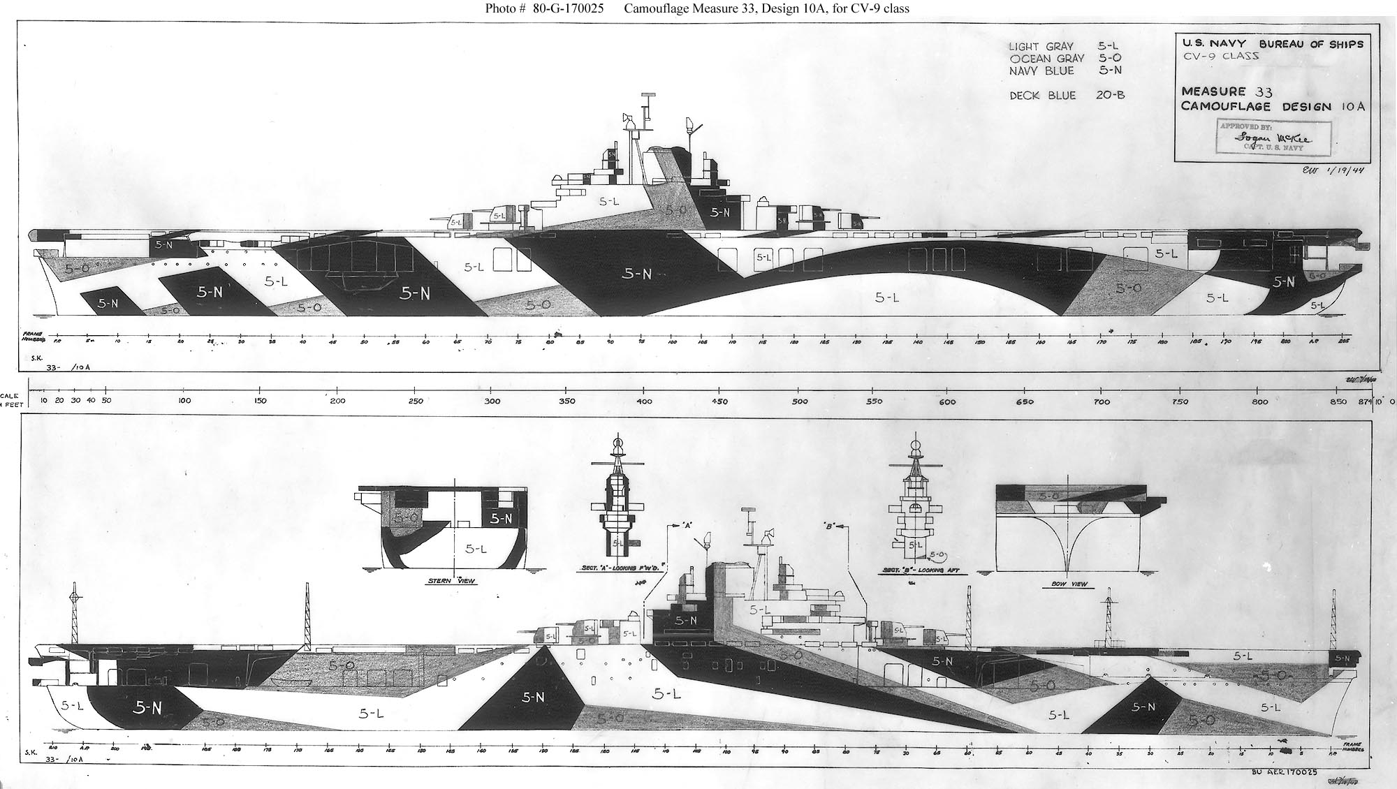
14. Colors. The official US Navy design sheets for Ms 33-10a specify Light Gray 5-L, Ocean Gray 5-O, Navy Blue 5-N and Deck Blue 20-B. There has been some discussion that the colors applied to Yorktown were actually Pale Gray 5-P, Haze Gray 5-H and Navy Blue 5-N on vertical surfaces with Deck Blue 20-B on horizontal surfaces. Keith Hufnagel painted his the latter.
I recommend studying Tracy White's comments in the Calling All Essex Class Fans thread. He has done considerable research on this class.
Posted: Mon Dec 03, 2007 3:49 pm
by ModelMonkey
The Island: New Bridge and Signal Deck
References indicate that some features of the kit's island are more accurate for a 1944
Yorktown (e.g. small, rounded bridge) while other features are more accurate for 1945 (e.g. Bofors configuration - see Note 1 below).
The most noticeable changes made to the island during the 1944 refit included the addition of an enlarged bridge, changes to the signal deck's port side, and the addition and relocation of radars.
GMM produces two superb PE detail sets for the Trumpeter kit and I will be using both for this build. They contain some very nice items, prominent in many photos of the real ship, such as the loudspeakers seen in the photo below.
Each Essex class ship was slightly different in radar fit. "Warship's Data 5: USS Yortown (CV-10)" by Robert F. Sumrall has terrific, detailed photographs of
Yorktown's radar fit as it changed throughout her service life.
The photo on Page 35 indicates where each of the GMM PE radars should be installed for Yorktown's 1945 fit.
The mast platforms located between the tripod legs are also GMM PE. The GMM parts are connected making them easier to align. To ensure that the platforms are positioned at the correct height, locate the upper platform so that it is even with the funnel cap service walkway (base of the cap).
Although the most dramatic alterations to
Yorktown were made during the late 1944 refit, by the spring of 1945 additional railings had been installed along the funnel cap service walk and some other radar changes had been completed.
ShipCamouflage.com, a terrific reference, has the official, approved Ms 33-10a pattern used for Yorktown. (See below). Check photos to see how it was applied to the ship. Photos indicate there were minor variations.
Although I chose the colors stated in official design sheets for Ms 33-10a (5-L, 5-O, 5-N and 20-B), there has been some discussion that the colors applied to
Yorktown were actually Pale Gray 5-P, Haze Gray 5-H and Navy Blue 5-N on vertical surfaces with Deck Blue 20-B on horizontal surfaces. Keith Hufnagel chose the latter for his terrific build. (See:
http://www.modelshipgallery.com/gallery ... index.html)
Posted: Mon Dec 03, 2007 3:52 pm
by ModelMonkey
Shell (Hull) Plating
Replicating hull plating on a model can be accomplished many ways. In 1/350 scale the hull plates are very thin so the technique I chose replicates raised strakes using various layers of sprayed-on automotive red primer.
A ship's skin is made up of many steel plates and is called shell plating. Essex class ships' shell plating pattern is conspicuous in photographs. Careful study of photographs is necessary to learn the plating pattern and to determine which strakes overlap the others.
Tracy graciously sent me some photos of Lexington which were very helpful and Keith sent me scans of the actual ships' plating plans (thanks, gentlemen!)
Posted: Mon Dec 03, 2007 3:52 pm
by ModelMonkey
Hull Plating Butt Straps
The vertical joints between hull plates above the waterline for most of the hull on the real ship were reinforced with metal strips called "butt straps" visible in photos below of CV-21. These have been replicated using 0.010 thick styrene strips glued to the strakes then sanded very thin after the glue hardened. See photos of the model later in this thread.
Posted: Mon Dec 03, 2007 3:55 pm
by ModelMonkey
Hangar Deck detailing begins.
Using
Anatomy of the Ship: The Aircraft Carrier Intrepid (AOTS) as a guide, the hangar deck can be further detailed and improved.
Detailing the hangar deck is the most labor-intensive, scratch-building effort of this model.
To best see the hangar deck, the modeler will want to open some or all of the roller doors. I chose to open them all as well as vents on the kit's bulkhead parts. The PE hatches are from the GMM set.
The Trumpeter kit's hangar deck bulkheads are simplified in that many interior structural details have been omitted. Many of these details are visible from outside the ship when the roller doors are open. Omissions include the transverse flight deck supports. These supports look like transverse bulkheads jutting into the hangar bay and are very conspicuous on the real ship. The transverse flight deck supports carried the weight of the flight deck above and buttressed the ship's sides.
In order to properly fix the modified bulkheads to the hangar deck, several parts-locating blocks molded onto the hangar deck parts have been removed.
Posted: Mon Dec 03, 2007 3:55 pm
by ModelMonkey
Hanger Deck, aft.
In order to continue, hangar deck bulkheads are fixed in place. The kit
parts fit here is terrible, due to the thickness of the hangar deck parts as Tracy
pointed out, so much sanding and putty was required on the hull exterior to close
the open joints. Some interior bracing of the starboard side vent trunk parts
was also needed as the kit parts came warped giving the assembled vent trunk
bulkheads a Coke bottle shape when viewed from above. The hangar deck is
now ready for detailing ("Light Labyrinths", ladders, ammo hoists, etc.), further
painting and cleanup.
Note that the larger roller door tracks have been replaced by Evergreen I-beam
strips.
Posted: Mon Dec 03, 2007 3:55 pm
by ModelMonkey
Hanger Deck, midships. Interior images of the vent trunk from the film "The Fighting Lady" (Yorktown's nickname) show the words "BEWARE OF PROPELLER" painted in red flush with the aft edge of the vent trunk. Note, singular, not "PROPELLERS"
Note that it is believed that not all of the footage in that film was taken aboard Yorktown so this safety reminder may have been painted on the vent trunk of another ship. But I like the detail (and the movie!), it will be very visible through the open roller doors of the midships elevator, so I decided to include it on the model.
Posted: Mon Dec 03, 2007 3:59 pm
by ModelMonkey
Improving the kit's Flight Deck parts
Some observations of the flight deck parts of Trumpy's 1/350 Yorktown:
1. The kit's flight deck parts have the ship's two as-built portside flight deck cutouts. These cutouts provided space for two Bofors mounts. During the August-October 1944 refit, the Bofors mounts were lowered and the flight deck cutouts were filled in.
2. Flight deck surface detail is a vast improvement over Trumpy's earlier Hornet kit, specifically, planking and tie-down strips look much, much better.
3. The flight deck is divided into three sections. The three flight deck sections are not the same thickness so joining them for a smooth flight deck surface is tricky. I also found that removing locator strips on the parts' undersides aids in the fit of the flight deck to the hull's bulkheads.
4. The 21 arrestor cables may be more accurate for an early Essex; too many for 1944-1945. During the frantic night recovery following the June 19, 1944 "Great Marianna's Turkey Shoot" - the unprecedented event where Admiral Mitscher ordered the lights turned on to guide in air groups out of gas - Yorktown's LSO was landing planes nearly simultaneously on the number 2 wire and the number 9 wire suggesting Yorktown only had nine arrestor cables at that time (The Fighting Lady, Clark Reynolds, pg. 164). Or perhaps Yorktown only had nine arrestor cables rigged but mechanisms for 21. I'll defer to Tracy for confirmation.
4. As talked about in earlier posts, the gallery deck is lacking any detail on the vertical surfaces. No slam on Trumpeter as Tamiya omits the same details with their kits.
5. The real ship has very noticeable longitudinal members between the structural supports for the flight deck on the forecastle (parts D13, D15 and D16 on the short hull kit). The framing detail on part D16 is very heavy and the part's "wings" should extend outward much farther, similar to the wings of parts D13 and D15.
6. The flight deck parts' undersides are not detailed at all. There are no kit parts to replicate the hangar deck overhead.
7. The underside of the port side flight deck overhang is replicated by separate kit parts but they lack detail. Once installed, there is a rather large, unsightly gap along the center of the gallery deck.
Posted: Mon Dec 03, 2007 4:04 pm
by ModelMonkey
Improving the kit's Elevator Wells
The kit's forward elevator well bulkhead parts are without any detail. 97 parts have been added to replicate various features such as equipment panels, structural members, pulleys, cables and roller tracks. Note that the forward elevator moved along tracks fixed to the bulkheads. The aft elevator did not.
The forward elevator well was detailed according to photos of Hornet post-war, much busier than depicted by the kit. During the war, the bulkheads were usually painted a dark color, probably Navy Blue 5N. After making these new bulkheads, it was pointed out to me that during WWII, the forward bulkhead did NOT have the cables and pulleys seen in the postwar photo so changes have to be made.
The kit's forward elevator part has been inserted into an opening I cut into the kit's hangar deck.
Posted: Mon Dec 03, 2007 4:08 pm
by ModelMonkey
Painting the Hull
USS Yorktown was wearing
Ms. 33-10a in April, 1945 at the time her air group, Air Group 9, helped sink
IJN Yamato.
For those building
Yorktown as she appeared in 1945, note that she had been repainted during the August-October, 1944 refit slightly differently than her 1944 Ms. 33-10a pattern so check your resources closely. Pictorial Histories Publication
Warship's Data 5: USS Yorktown (CV-10) by Robert F. Sumrall (ISBN 0-929521-45-5), had several good photos of the ship in 1945 (post-1944 refit). Particularly useful in determining
Yorktown's 1945 camouflage pattern were photos found on pages 1, 29, 35, 46, 48, & 49. They are particularly helpful as they show the ship freshly painted during its post-1944 refit cruise from all four quarters.
Still some touch-up to do but hull painting is largely complete.
The close-up photos below show the shell plating detail to good effect:
If you are building your model as the ship appeared in 1945, avoid the photo on page 60 of "Warship's Data 5: USS Yorktown (CV-10)". Although captioned "March 1945", the Bofors mount locations indicate that the photo is actually of
Yorktown before the 1944 refit. The camouflage pattern in 1945 is slightly different than the pre-refit pattern.
Although I prefer WEM enamels, I am now airbrushing indoors so this model is being painted with ModelMaster and Poly Scale acrylics made by Testors. Despite reports that ModelMaster Marine colors and PolyScale marine colors have been discontinued, they are all available directly from
Testors Corporation
Posted: Mon Dec 03, 2007 4:11 pm
by Foeth
Great work

Posted: Mon Dec 03, 2007 4:15 pm
by ModelMonkey
Thank you, EJ!
Improving the Gallery Deck bulkheads:
The real ship's Gallery Deck was a busy place with lots of interesting fittings, openings, devices, etc. all begging to be added to your kit. One significant method of access to the
Gallery Deck was through many openings in the bulkhead just below the flight deck. These openings were conspicuous on the real ships and by including them in your model the kit's appearance can be improved.
To do so on my model, I studied photographs of several ships of the class, many provided by Tracy White, of USS Lexington and USS Franklin (ships whose structural appearance was nearly identical to Yorktown), in order to locate the openings and determine their size.
In the photos below, the flight deck is not yet fixed to the hull and a light coat of deck blue has been sprayed on the flight deck to help identify any seam problems that need fixing. Also note that Yorktown had the two flight deck cutouts for the port Bofors (nearest the 5-inch guns) filled in during her August-October, 1944 refit.
IMHO, Trumpter did a great job on the flight deck planking and tie-down strip detail for their 1/350 scale Essex class kits.
There are many techniques you can use to add Gallery Deck bulkhead openings to your model. The technique I chose to replicate the openings shown in the photos above was to create new openings using thin, 0.010" (0.25mm) thick styrene strips overlaying the kit parts.
According to photos and AOTS drawings, the gallery deck bulkhead height should be about 0.24" (6.0mm). Instead of using one strip 0.24" wide, build up to 0.24" by using three Evergreen .010" x .080" (0.25mm x 2.0mm) strips laid side by side. The square openings should be .080" x .080" (2.0mm x 2.0mm). By leaving 0.080" wide gaps in the center strip, you will create the square openings. Step-by-step:
1. Mark the location and type of opening (rectangular, square, oval, etc.) on the kit parts. If you are using a PE set with perforated gallery deck catwalks, be sure to check bulkhead opening locations against the PE catwalk parts to ensure your openings are in logical locations with respect to the catwalks. This is especially important starboard side aft. The catwalk above the starboard aft crane area is positioned on the bulkhead higher than other catwalks. A bit of care here will save you from having finding out an inclined ladder to that raised area lays across an opening.
2. Grind out a cavity for the openings in the kit parts using a Dremel tool (or equivalent) slightly larger than the opening. You can achieve a more realistically thin edge for the openings if you grind out a cavity in the kit parts before applying the styrene strip.
3. Lay down the first (top) strip even with the top edge of the flight deck.
4. Lay the second (middle) strip onto the bulkhead leaving gaps 0.080 wide for the square openings over the cavities you ground out in the earlier step. Using a 0.080" wide scrap styrene piece as a spacer will help you make perfectly uniform gaps.
5. Lay down the last (bottom) strip.
6. After the glue has set, sand smooth.
7. Add the 20mm Oerlikon platforms and other details of your choosing.
Posted: Mon Dec 03, 2007 4:16 pm
by Devin
Steve, your posts make me look longingly at the USS Essex I have sitting above my workbench. I got her to the point that my scratch built hangar detail was added (not as much as yours, though!), and she's ready to have the hull plating applied and deck glued on, but I put her aside and haven't touched her in nine months.
Great work on yours, I'll look to this for the pitfalls I need to be aware of.
-Devin
Posted: Mon Dec 03, 2007 4:30 pm
by MartinJQuinn
Brilliant work...also a brilliant idea to split this post out into it's own thread.
Posted: Mon Dec 03, 2007 5:59 pm
by ModelMonkey
EJ, Devin, and Martin, thank you so much for your kind compliments!
Improving the Flight Deck sections' underside:
The real ship's Flight Deck was supported by various structural trusses and members that were visible from below. Here you can see some initial work to add structural details to the underside of Trumpy's 1/350 Flight Deck parts forward as well as the 20mm galleries. There are 82 Evergreen styrene pieces added in this step so far, all visible in the first photo. The members under the Flight Deck are .020"x.060" (0.5mm x 1.5mm). The parts added to the 20mm galleries are .010" x .125" (0.25mm x 3.2mm).
Posted: Tue Dec 04, 2007 6:40 am
by nick
Very amazing detail Steve!
I appreciate your hardwork for giving us the info abot the Yorktown!