I couldn’t quite get the crossing of the main topmast stays out of my mind. To sort this out, I first had to detach the two stays. And here it becomes clear once again how beneficial it is to build according to the original design: I simply had to loosen the two lanyards on the deck behind the foremast, and the two stays could be unhooked.
To properly evaluate this area, all the backstays are still missing. There are the three standing backstays, the breast backstay and the flying backstay, both of which could be repositioned flexibly as required. To get a feel for it, I threaded in five coloured strings.
And I could already see that it might be pretty tight up there.
And as you can see, the breast backstay and the two front standing backstays pass very close to the top.
Down below, however, everything falls into place quite logically.
I prepared the breast backstay with a horseshoe splice. To do this, I clamped the rope to a spare mast.
The excess lines are then trimmed. The normal standing backstays are then ready more quickly, just as with the lower masts. Fitted around the masthead.
The shrouds are then quickly fitted.
I might have been better off making the breast backstay as single ropes, as it’s so difficult to get past the sister blocks between the first two shrouds. The rear standing backstay was also made as a horseshoe splice, resulting in the awkward twist you can see here.
So I replaced these with single ropes, which allowed me to get past more easily. Next comes the flying backstay, which was fitted last; this one isn’t dressed. It’s also made up of two single ropes, which can be positioned better.
And then the main topmast stay and its preventer stay are back in place. Once the main topmast stay is set and the preventer stay is threaded through the eye as described, the whole setup suddenly makes perfect sense


Because of my imitation of serving, the whole thing is naturally a bit wider than in the original, but it still fits and the two stays don’t seem to be pinching each other.
There will be one more brief interlude: In the fighting top level, the stays running there still need to be served. I’ve marked the positions with light-coloured thread.
And this is what the complete set up looks like now.
And finally, White Jacket inspecting his workplace.
Enjoy, XXXDAn
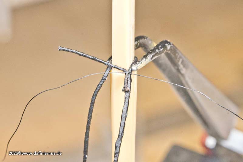
I couldn’t quite get the crossing of the main topmast stays out of my mind. To sort this out, I first had to detach the two stays. And here it becomes clear once again how beneficial it is to build according to the original design: I simply had to loosen the two lanyards on the deck behind the foremast, and the two stays could be unhooked.
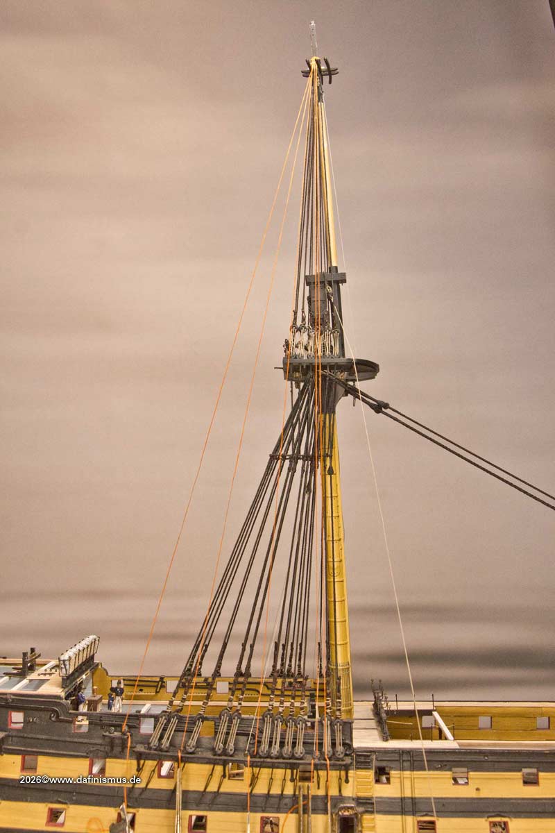
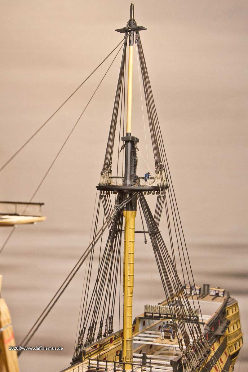
To properly evaluate this area, all the backstays are still missing. There are the three standing backstays, the breast backstay and the flying backstay, both of which could be repositioned flexibly as required. To get a feel for it, I threaded in five coloured strings.
[img]https://www.mediaharmonists.de/bilder/Sammler44/Victory_topmast_stays_260612_6688.jpg[/img]
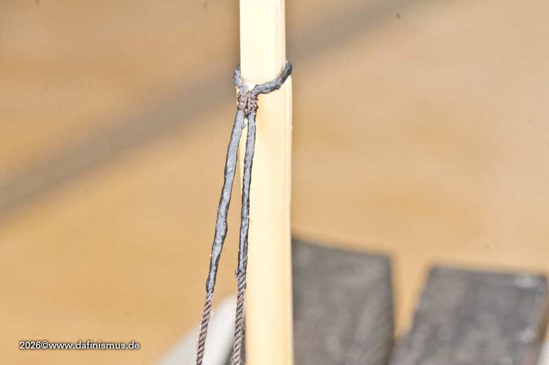
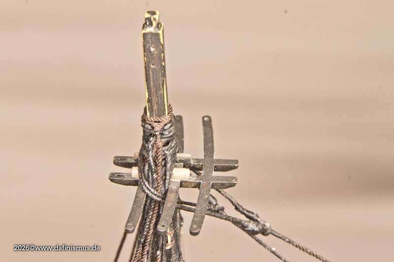
And I could already see that it might be pretty tight up there.
[img]https://www.mediaharmonists.de/bilder/Sammler44/Victory_main_topmast_stays_260612_6711.jpg[/img]
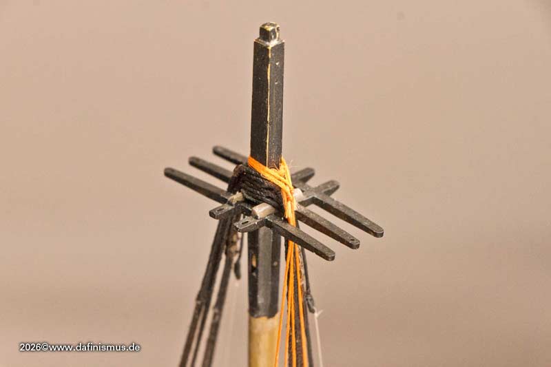
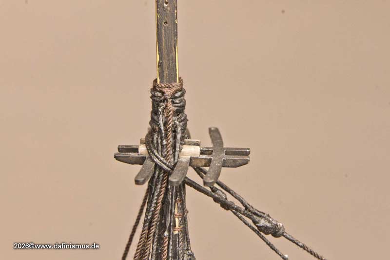
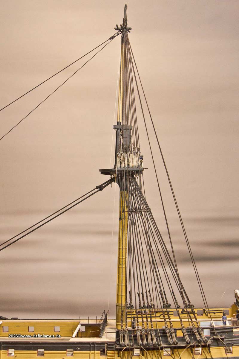
And as you can see, the breast backstay and the two front standing backstays pass very close to the top.
[img]https://www.mediaharmonists.de/bilder/Sammler44/Victory_main_topmast_stays_260612_6699.jpg[/img]
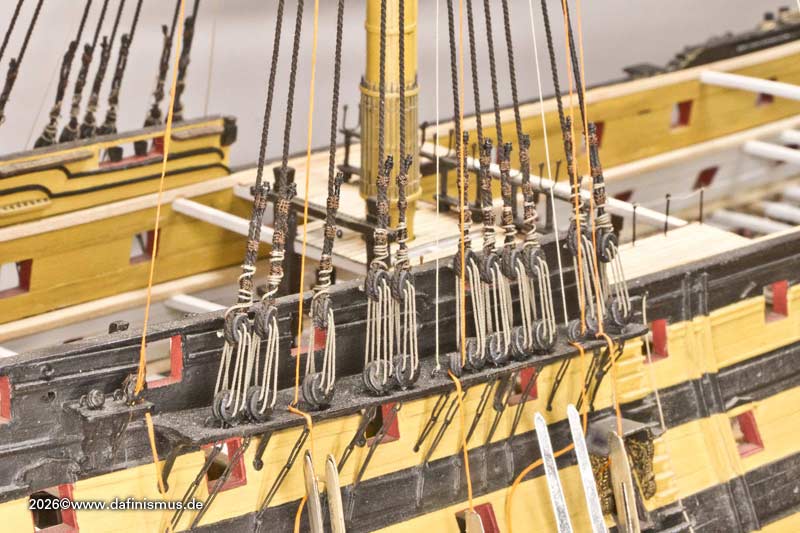
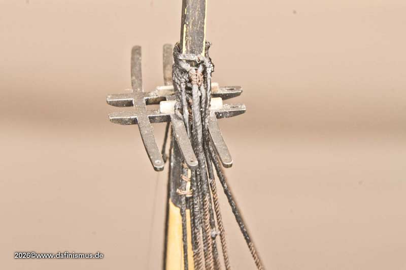
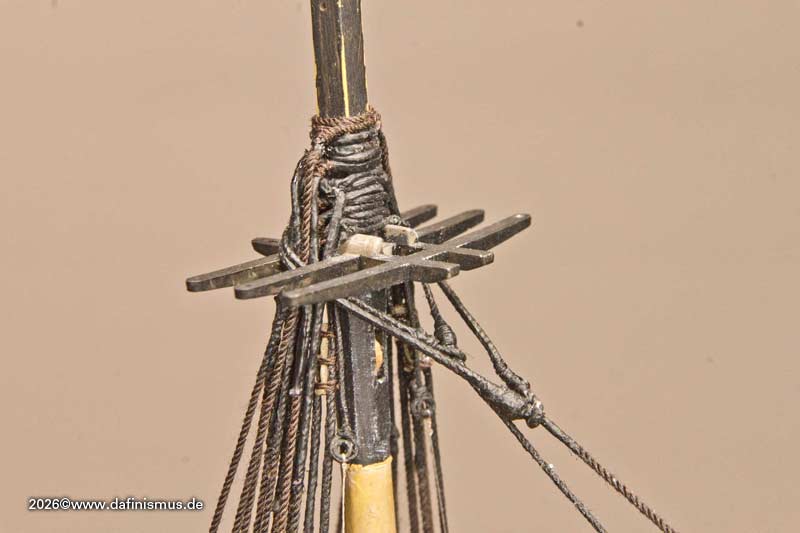
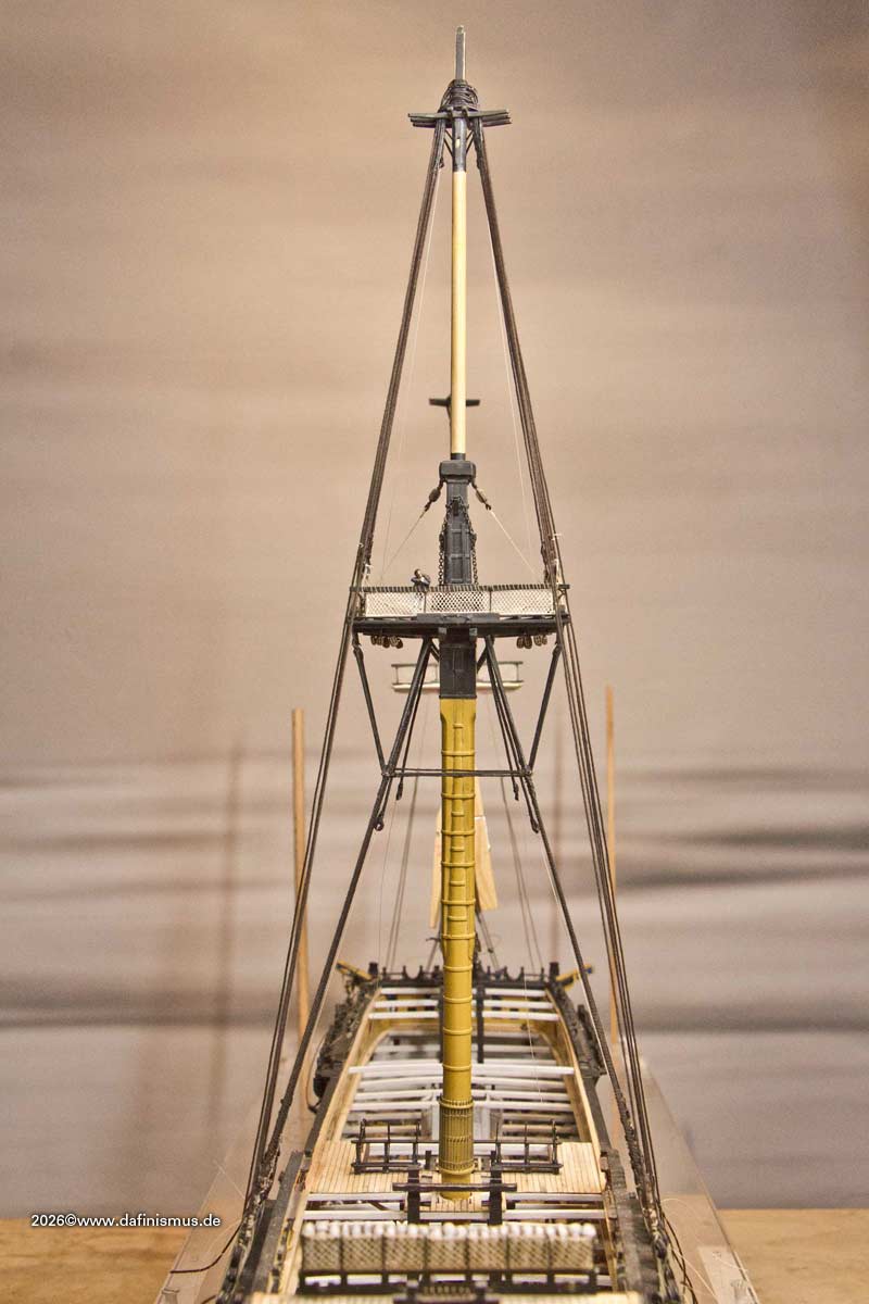
Down below, however, everything falls into place quite logically.
[img]https://www.mediaharmonists.de/bilder/Sammler44/Victory_main_topmast_stays_260612_6692.jpg[/img]
I prepared the breast backstay with a horseshoe splice. To do this, I clamped the rope to a spare mast.
[img]https://www.mediaharmonists.de/bilder/Sammler44/Victory_topmast_stays_260613_6714.jpg[/img]
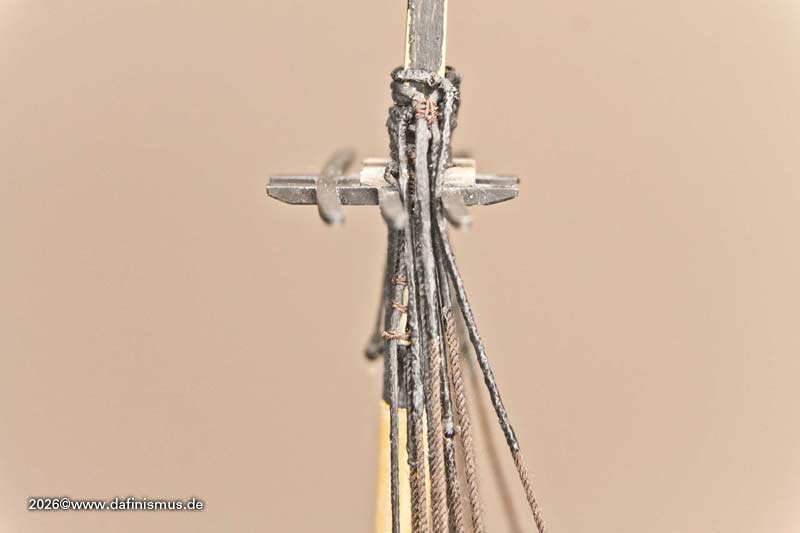
The excess lines are then trimmed. The normal standing backstays are then ready more quickly, just as with the lower masts. Fitted around the masthead.
[img]https://www.mediaharmonists.de/bilder/Sammler44/Victory_topmast_stays_260613_6727.jpg[/img]
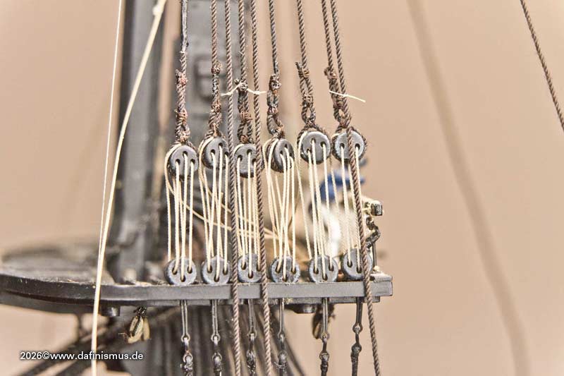
The shrouds are then quickly fitted.
[img]https://www.mediaharmonists.de/bilder/Sammler44/Victory_topmast_stays_260614_6731.jpg[/img]
I might have been better off making the breast backstay as single ropes, as it’s so difficult to get past the sister blocks between the first two shrouds. The rear standing backstay was also made as a horseshoe splice, resulting in the awkward twist you can see here.
[img]https://www.mediaharmonists.de/bilder/Sammler44/Victory_topmast_stays_260614_6739.jpg[/img]
So I replaced these with single ropes, which allowed me to get past more easily. Next comes the flying backstay, which was fitted last; this one isn’t dressed. It’s also made up of two single ropes, which can be positioned better.
And then the main topmast stay and its preventer stay are back in place. Once the main topmast stay is set and the preventer stay is threaded through the eye as described, the whole setup suddenly makes perfect sense :-)
[img]https://www.mediaharmonists.de/bilder/Sammler44/Victory_topmast_stays_260614_6773.jpg[/img]
[img]https://www.mediaharmonists.de/bilder/Sammler44/Victory_topmast_stays_260614_6781.jpg[/img]
[img]https://www.mediaharmonists.de/bilder/Sammler44/Victory_topmast_stays_260614_6782.jpg [/img]
[img]https://www.mediaharmonists.de/bilder/Sammler44/Victory_topmast_stays_260614_6788.jpg[/img]
Because of my imitation of serving, the whole thing is naturally a bit wider than in the original, but it still fits and the two stays don’t seem to be pinching each other.
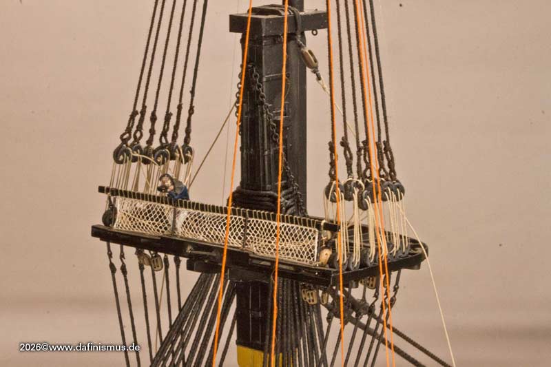
There will be one more brief interlude: In the fighting top level, the stays running there still need to be served. I’ve marked the positions with light-coloured thread.
[img]https://www.mediaharmonists.de/bilder/Sammler44/Victory_topmast_stays_260614_6751.jpg[/img]
And this is what the complete set up looks like now.
[img]https://www.mediaharmonists.de/bilder/Sammler44/Victory_topmast_stays_260614_6764.jpg[/img]
[img]https://www.mediaharmonists.de/bilder/Sammler44/Victory_topmast_stays_260614_6769.jpg [/img]
[img]https://www.mediaharmonists.de/bilder/Sammler44/Victory_topmast_stays_260614_6770.jpg[/img]
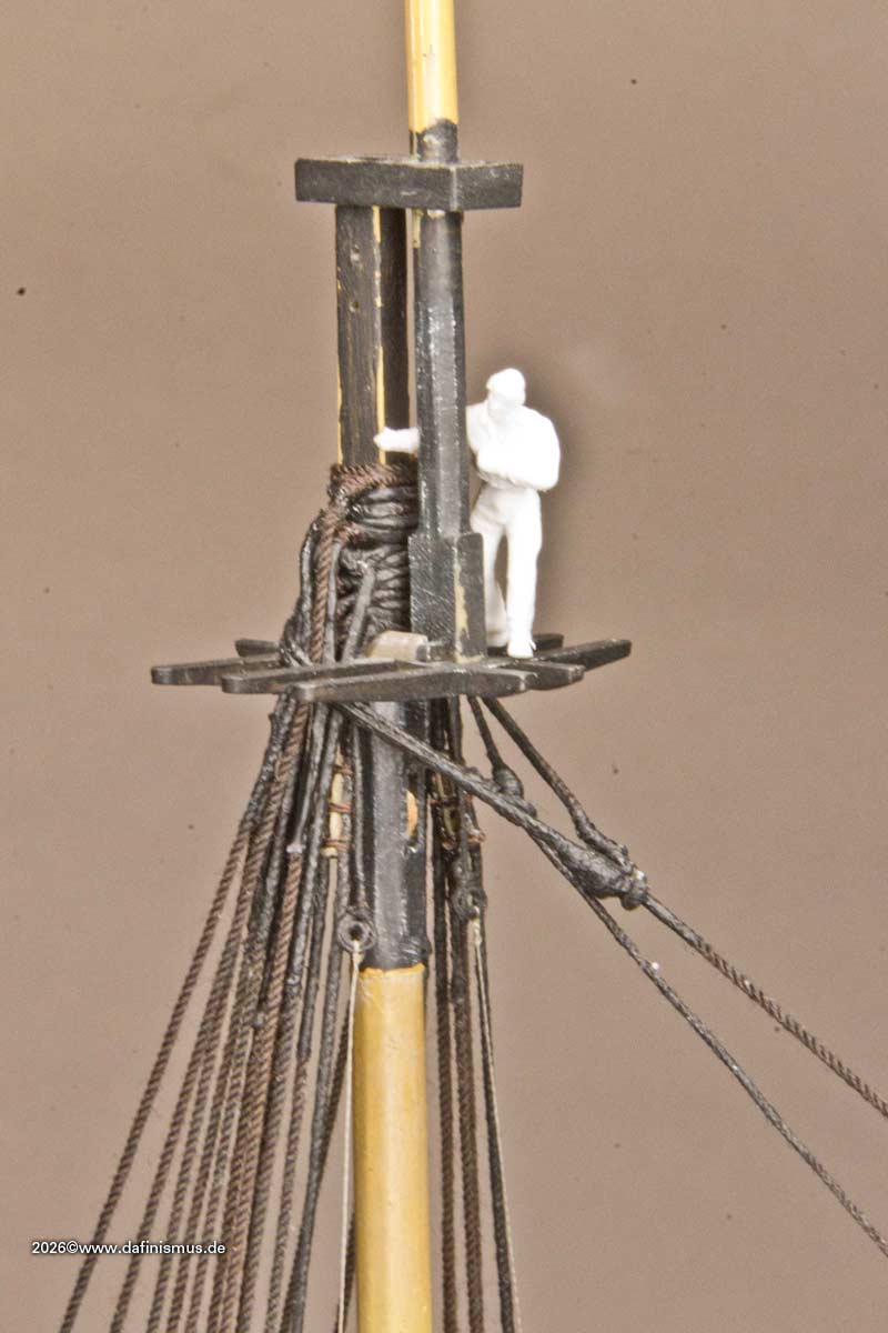
And finally, White Jacket inspecting his workplace.
[img]https://www.mediaharmonists.de/bilder/Sammler44/Victory_topmast_stays_260614_6811.jpg[/img]
Enjoy, XXXDAn