To HMS Victory and beyond

Moderators: BB62vet, MartinJQuinn, JIM BAUMANN, Jon, Dan K

User avatar
dafi
Posts: 1002
Joined: Mon Mar 12, 2012 11:13 am
Location: Ludwigsburg/Germany
Contact:

Re: To HMS Victory and beyond

Post by dafi »

And now something completely different: The Christ Child was in a very good mood before Christmas and delivered the first samples of the channel irons and hammock holders for my Constitution *jumping for joy*

Image

Image

And finally, I had a little time to tinker with it :-)

So, popcorn and beer at the ready, X-Files in the DVD player, and off to work with joy!

Image

See you on a ship yard on other side of the Atlantic.
posting.php?mode=edit&p=1092529

XXXDAn
To Victory and beyond ...
viewtopic.php?f=59&t=99050&start=60

See also our german forum for the age of Sail and History:
http://www.segelschiffsmodellbau.com
User avatar
dafi
Posts: 1002
Joined: Mon Mar 12, 2012 11:13 am
Location: Ludwigsburg/Germany
Contact:

Re: To HMS Victory and beyond

Post by dafi »

After being away for a while due to work on the Constitution and work in the mids Austria´s mountains, here’s a little something again concerning Victory.

I fancied continuing the gratings extravaganza of the upper decks upon the two lower decks as well. Since I was already at it. So I scaled and printed out the plans of the lower decks and checked how they lined up with the model.

Image

Then I modified the 3d print files for the upper decks and printed them ...

Image

... and added other already existing parts.

Image

Image

Image

And then the fine-tuning began. Transfer the printed parts onto the decks to mark out the cut-outs.

First, use the scalpel to mark the length and ...

Image

...then use the compass-scriber to mark the long sides.

Image

To saw out the openings, I use the fretsaw ...

Image

... and then scored along the length with a scalpel and snaped it simply off.

Image

That was a real nightmare of planning and fiddling about ...

Image

... naturally with a few casualties : )

Image

And suddenly just like that, the gratings were in place.

Image

Then was painting time for those parts involved.

Image

Image

The deck was given some colour shading along the run of the planks.

Image

Image

Image

Image

As it was still a bit too subtle, I added a bit of black ink in the same direction.

Image


I tried out a few things with the planks, like scribing the joints and so on. But none of it was convincing for my liking. Then came the winner: a very simple and straightforward pencil line.

Image

An old New Year’s Eve firework stick made a good ruler, as it allowed for a slight irregularity in the line despite the parallelism.

Image

And then I carefully removed the excess graphite with tape, otherwise it smudges – I really don’t like working with clear varnish. The visibility of the texture turned out just right, so that in my view it can also be a good alternative to visible decals.

Right then, best regards, DAniel
To Victory and beyond ...
viewtopic.php?f=59&t=99050&start=60

See also our german forum for the age of Sail and History:
http://www.segelschiffsmodellbau.com
User avatar
JIM BAUMANN
Posts: 5682
Joined: Mon Jan 10, 2005 5:30 pm
Location: Nr Southampton England

Re: To HMS Victory and beyond

Post by JIM BAUMANN »

very very excellent!

The pencil is an underrated tool--especially for the butt ends

In your gargantuan scale.... :big_grin: you can put all the butt ends in--but make the, a bit narrower a line than the for and aft planking--otherwise it can look like a chessboard....


In my small scales I put some random pencil strokes on- about 25 % of what would be there
-so that the observer when he/she -sees a butt end--believes they are there
But ( haha! ) it does not overwhelm the decking

weiter so!
JB
....I buy them at three times the speed I build 'em.... will I live long enough to empty my stash...?
http://www.modelshipgallery.com/gallery ... index.html

IPMS UK SIG (special interest group) www.finewaterline.com
User avatar
dafi
Posts: 1002
Joined: Mon Mar 12, 2012 11:13 am
Location: Ludwigsburg/Germany
Contact:

Re: To HMS Victory and beyond

Post by dafi »

Thank you Jim, very appreciated!

Anyway ...
OotB2.jpg
... somehow I had a vague recollection that, after the modelling show in Stuttgart last November, the transport box containing the ship had slipped out of my hands. I thought to myself, with the big biannual convention in Augsburg this weekend coming, I’d better have a look inside before.

I have to say, I’ve got my research wrong again. Firstly, I can’t remember the maintop mast being shot down, and secondly, the mizzen mast was severed from its base a bit higher up. So back to the research department to see where that incorrect information came from.

See you Saturday in Augsburg perhaps? The artist will be present ;-),

XXXDAn


PS: @marijn van gils Have a good look, that is the way it should look like :-)
To Victory and beyond ...
viewtopic.php?f=59&t=99050&start=60

See also our german forum for the age of Sail and History:
http://www.segelschiffsmodellbau.com
SG1
Posts: 404
Joined: Mon Apr 17, 2017 2:43 am
Contact:

Re: To HMS Victory and beyond

Post by SG1 »

Superlative rendering of planking, excellent work. Love the ruler! :cool_2:
User avatar
dafi
Posts: 1002
Joined: Mon Mar 12, 2012 11:13 am
Location: Ludwigsburg/Germany
Contact:

Re: To HMS Victory and beyond

Post by dafi »

Right then, I still owe you the resolution to that cliffhanger from Augsburg. But I’ve just been really busy lately :-)

The mizzen mast had simply snapped neatly just below the belay ring. I’d only made the mast as a test piece back then; it was never intended for the model. That’s why it had no reinforcement. A single skewershaft not only repairs it, it actually stiffens the whole thing. I don’t even need to glue it; it holds together really well just by being inserted. It was handy for fitting that I still had spare parts on hand, which allowed me to easily adjust the required diameters.

Image

Image

The main top mast was a bit more of a challenge – thinner and broken in the visible area. But here too, a reinforcement, this time made of 2 mm stainless steel wire, and it was patched up :-)

Image

Image

A bit more paint over it, no one can see anything anymore and that’s that :-)

Repair time: plastic, 28 minutes; removing and reinserting the lanyards of the main top, 1.26 hours and ...

...and there she was – less than 12 hours after the damage was discovered, the little beauty, with her slender stripes, was able to show herself off with her head held high at the exhibition in Augsburg.

Image

Image

Image

XXXDAn
To Victory and beyond ...
viewtopic.php?f=59&t=99050&start=60

See also our german forum for the age of Sail and History:
http://www.segelschiffsmodellbau.com
Mexspur
Posts: 1
Joined: Thu Jun 04, 2026 1:07 pm

Re: To HMS Victory and beyond

Post by Mexspur »

Great work.
I miss not being able to give you a “thumbs up”.
User avatar
JIM BAUMANN
Posts: 5682
Joined: Mon Jan 10, 2005 5:30 pm
Location: Nr Southampton England

Re: To HMS Victory and beyond

Post by JIM BAUMANN »

Very good-
-nothing worse than slender spars that bend or break.
(I today bent a brass yard-arm by knocking it :Mad_5: :Mad_6:
you have my sympathies!

Bravo for going through with the fixes!
Mfg
JB
....I buy them at three times the speed I build 'em.... will I live long enough to empty my stash...?
http://www.modelshipgallery.com/gallery ... index.html

IPMS UK SIG (special interest group) www.finewaterline.com
User avatar
dafi
Posts: 1002
Joined: Mon Mar 12, 2012 11:13 am
Location: Ludwigsburg/Germany
Contact:

Re: To HMS Victory and beyond

Post by dafi »

Thanx Mexspur and Jim.

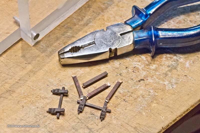
And after that? After that, things went on as they always do: the heavy-duty clearing tools came out.

Image

But what had happened yet again?

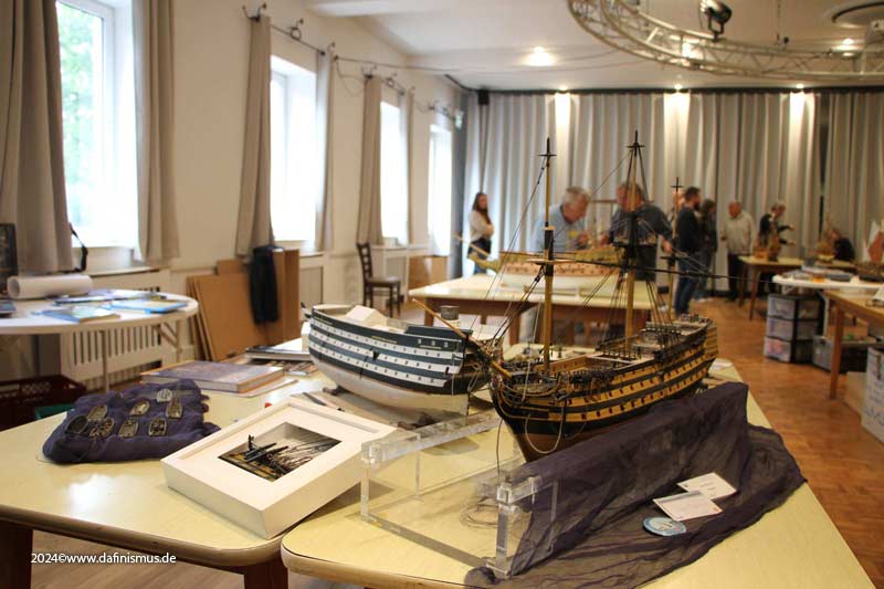
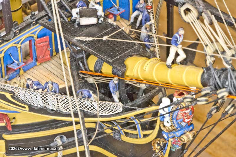
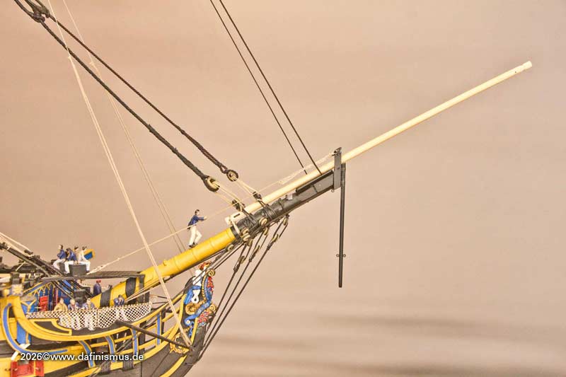
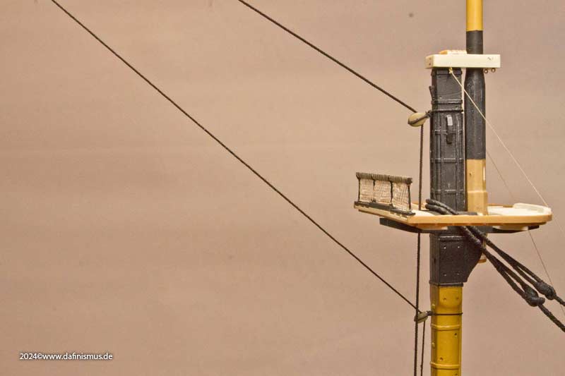
As I always want to show at least a little progress – apart from repairs – at exhibitions, I had at least fitted the main topmast stay for Augsburg as a little treat.

Image

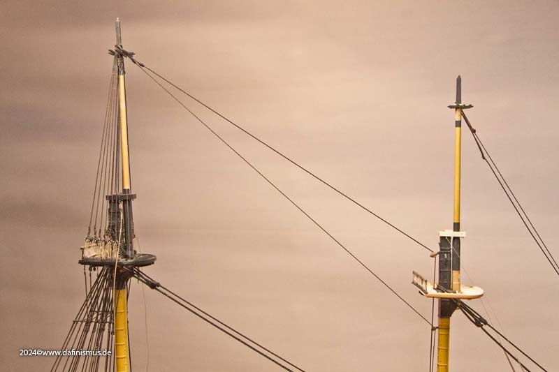
To do this, however, I had to attach the eyebolts in the middle deck, which wasn’t very elegant.

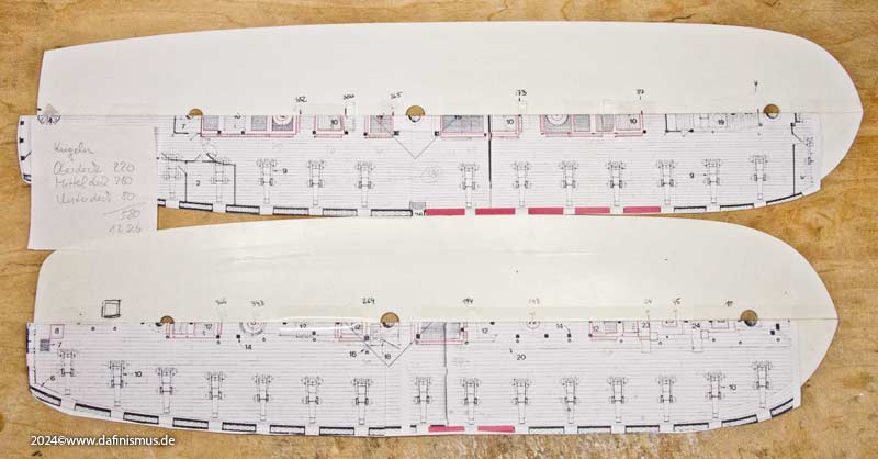
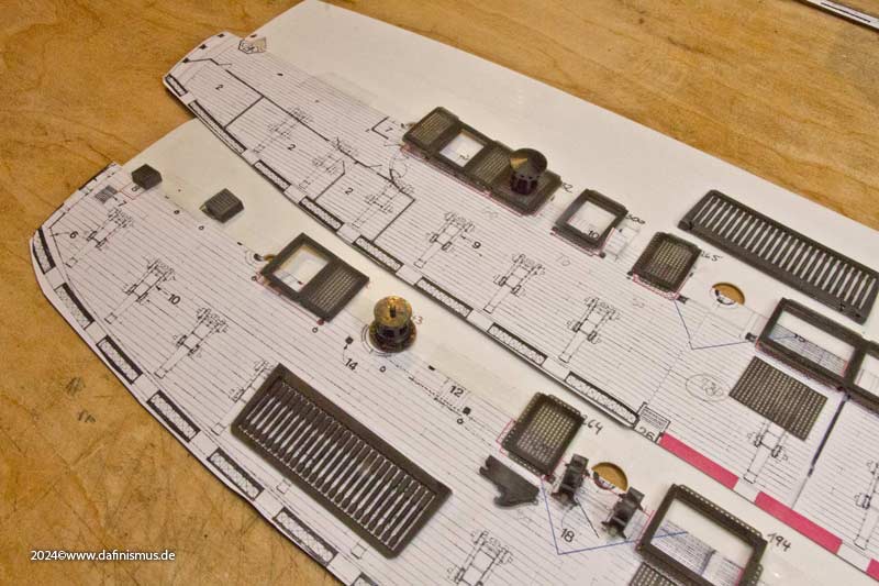
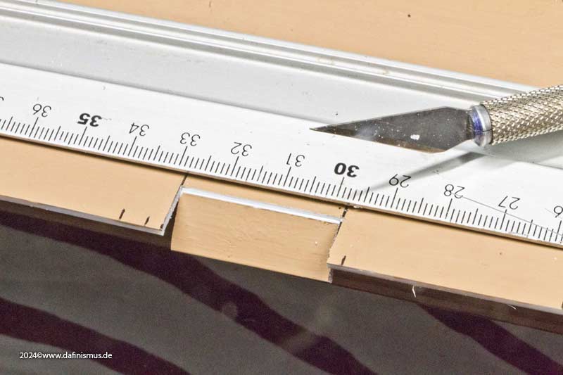
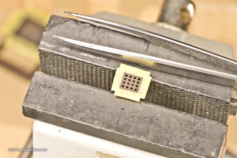
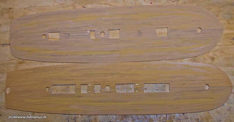
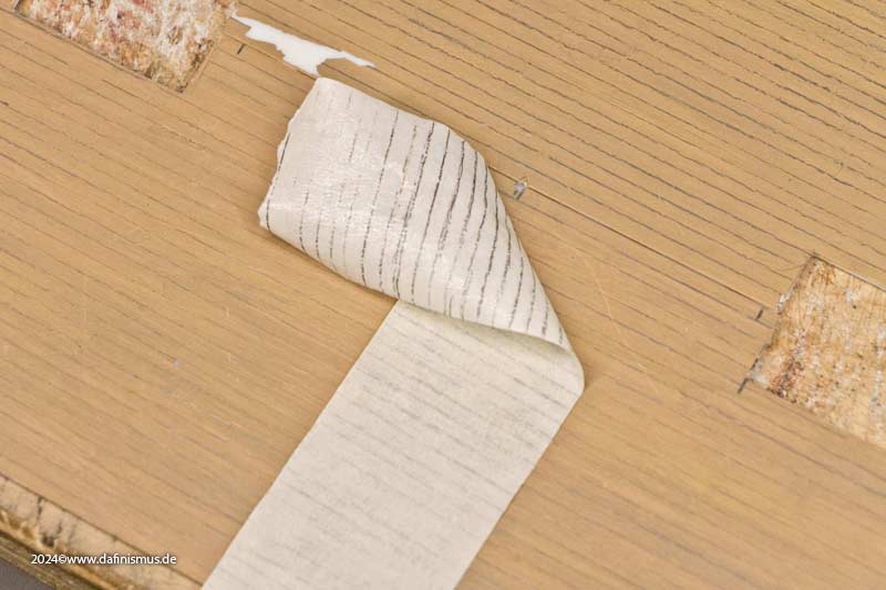
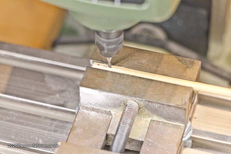
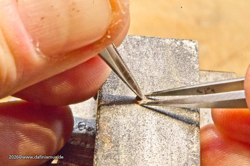
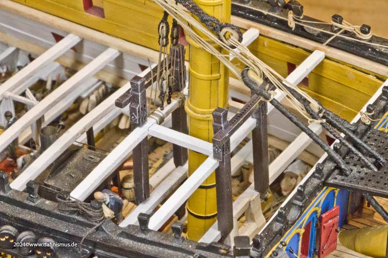
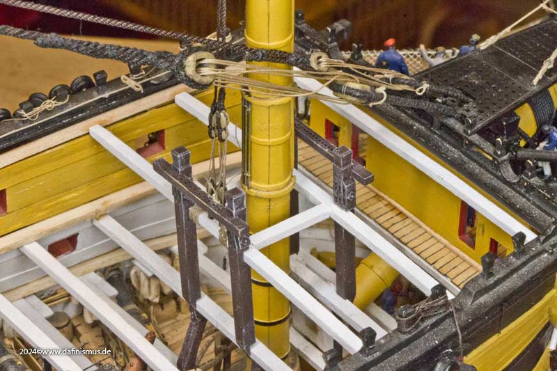
So I installed new deck beams in the forecastle and placed the necessary support beams underneath. As there’s a change of rhythm here, I used those funny angled supports...
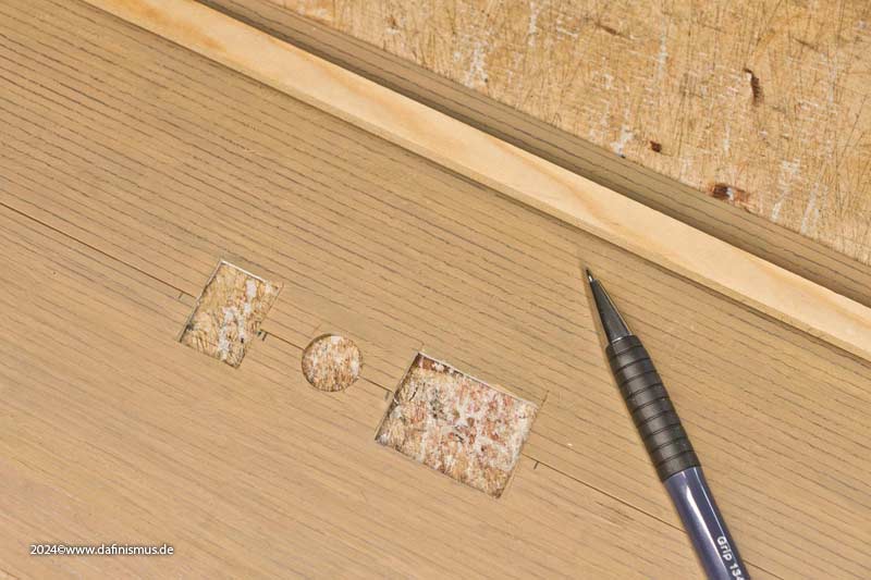
to mark it out,
Image

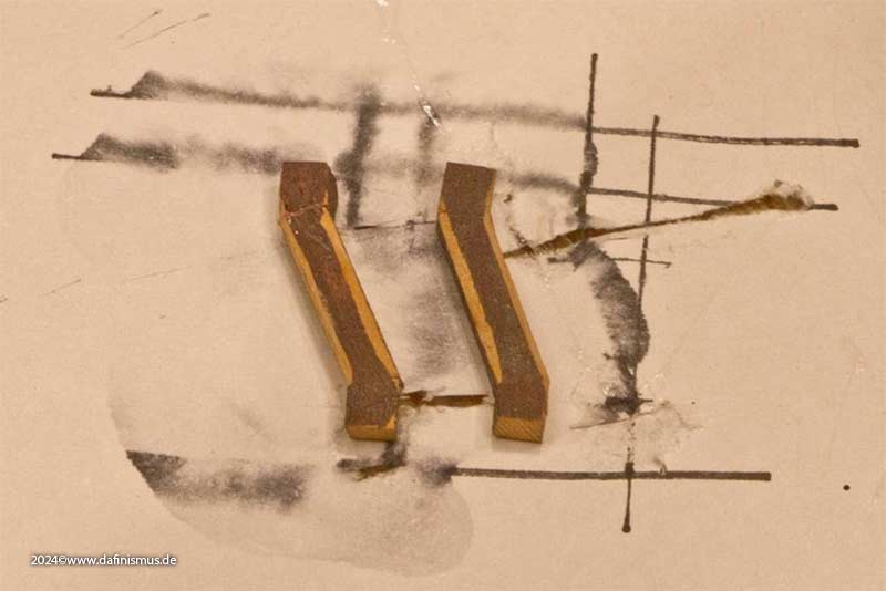
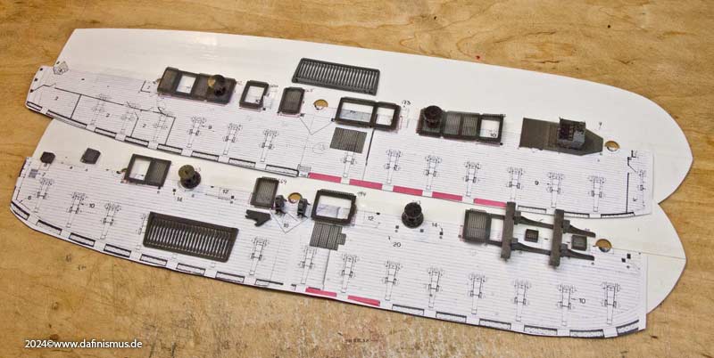
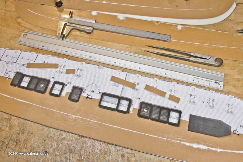
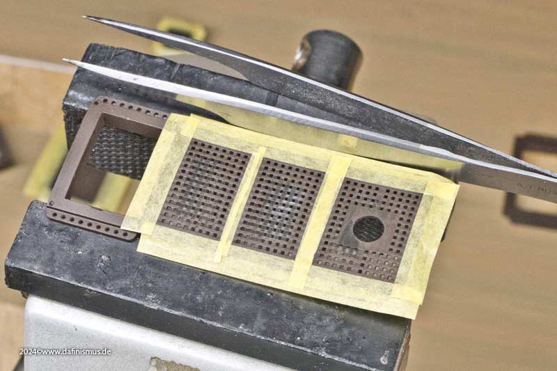
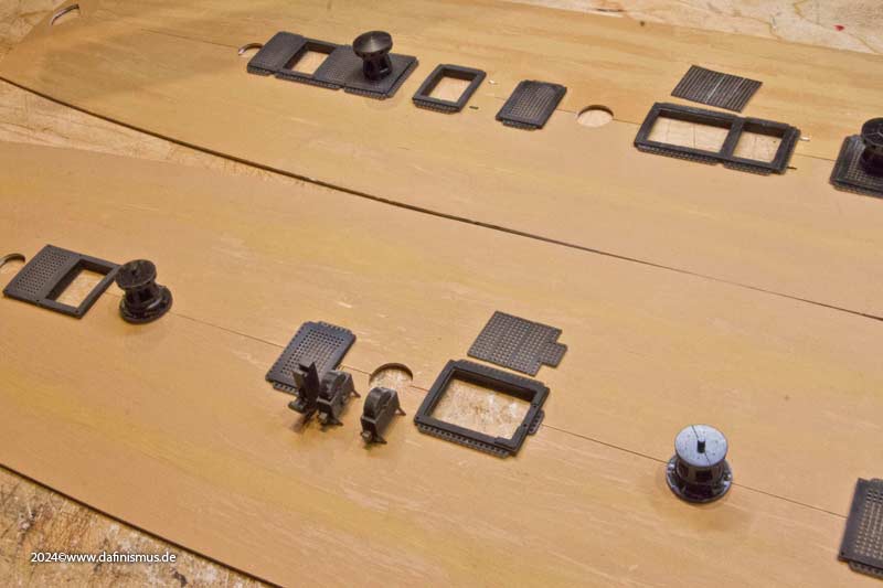
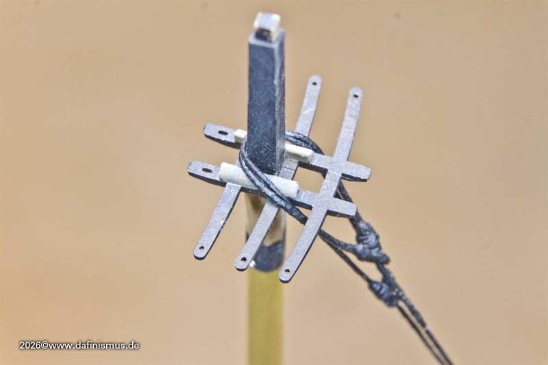
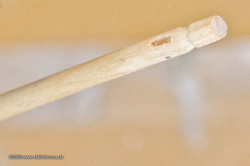
...glued them to a piece of paper to ensure they were perfectly aligned. A first coat of paint makes it easier to get the chamfers even. After that, the lower parts of the bitts were positioned in line with the supports underneath. For the upper bitts parts, I used my resin ones. It was tricky to position the holes for their tenons correctly, as they were placed very close to the edge of the beams ends. Nevertheless, I went ahead and positioned them.

Image

Image

Image

Image

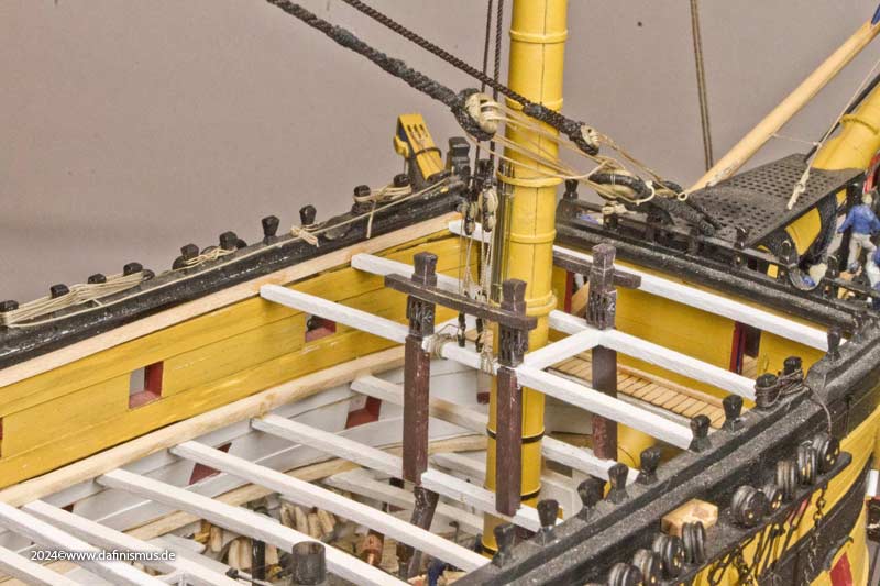
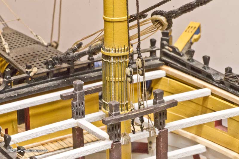
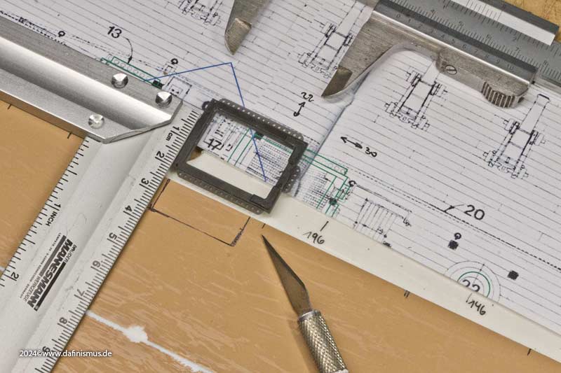
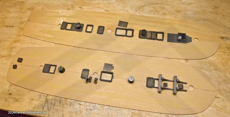
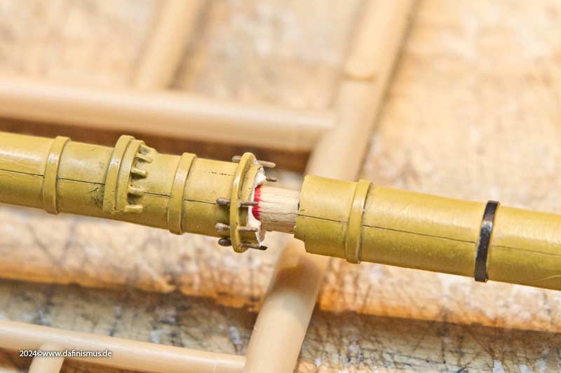
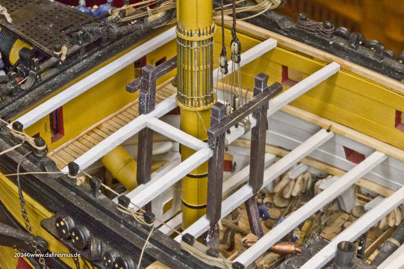
At first glance, it looks quite alright, but on closer inspection you can see the poor transition between the lower and upper sections of the bitts.

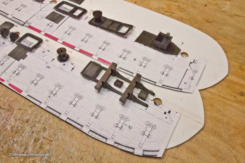
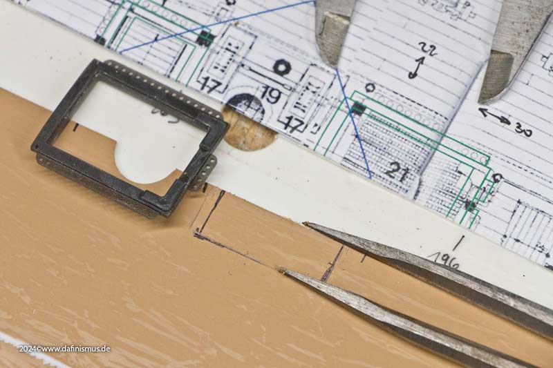
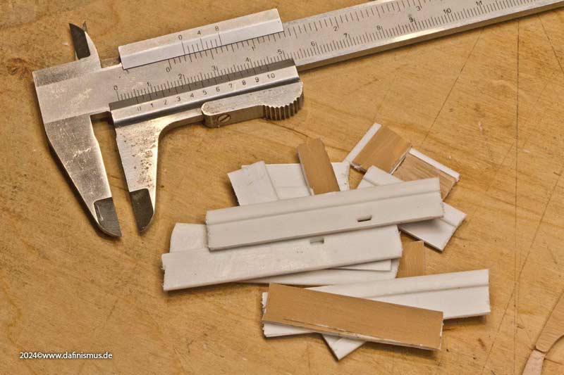
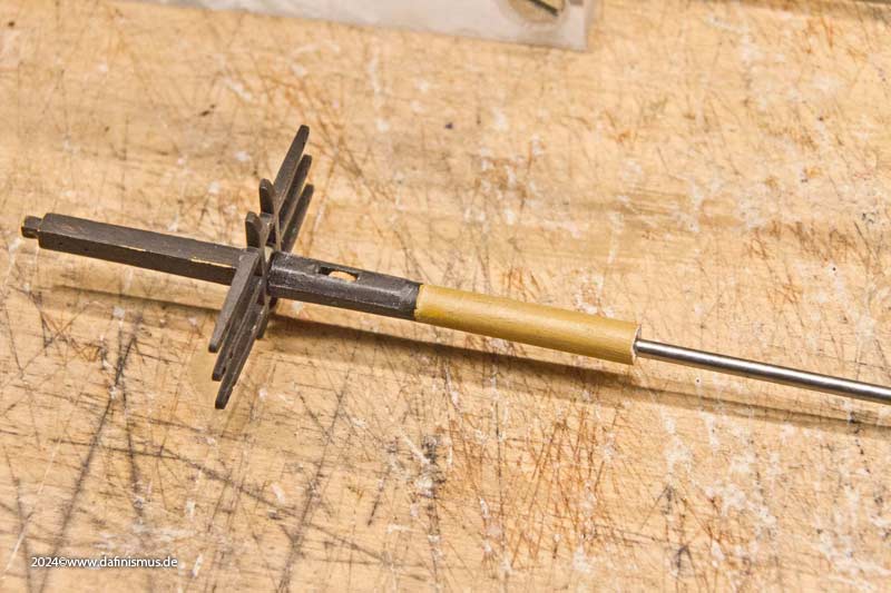
So, out come the big pliers and off it goes :-)

Image

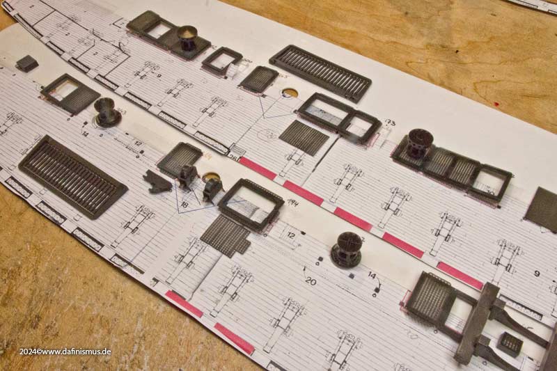
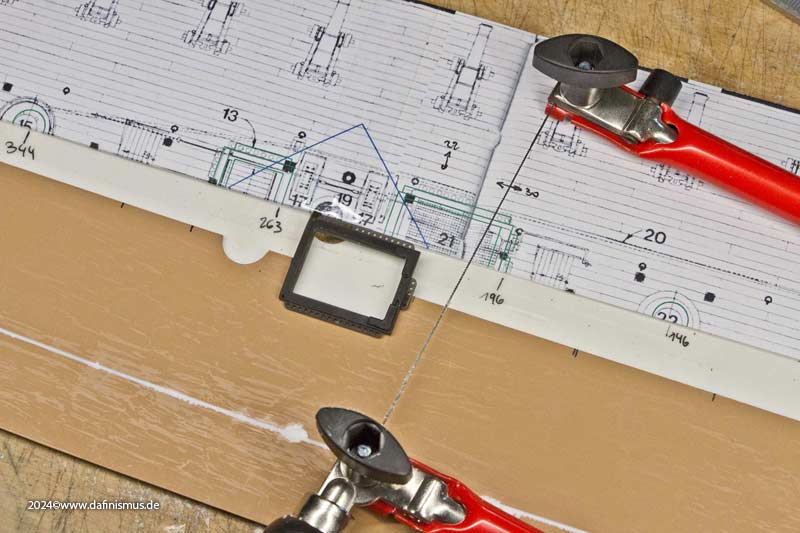
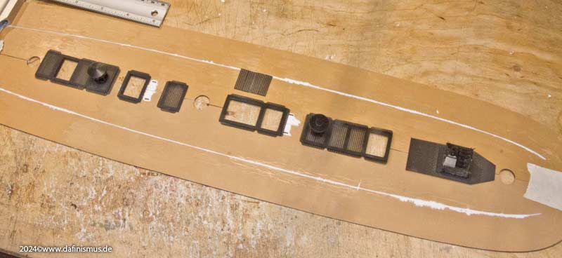
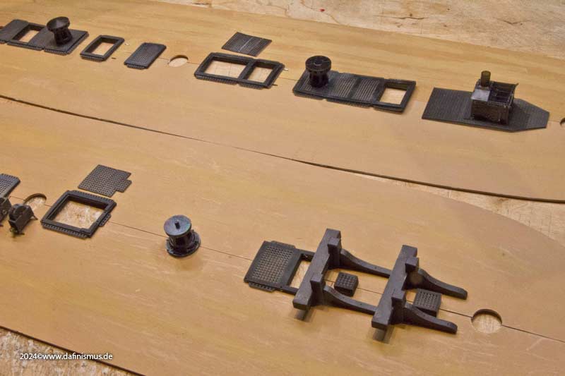
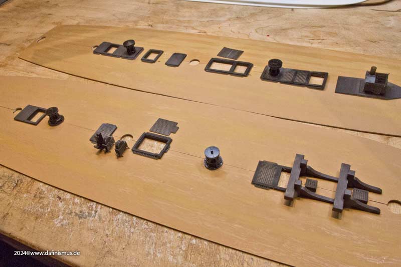
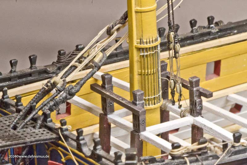
Then I reprinted the bitts with the lower section included and the corresponding cut-outs, and it looks much better already.

Image

Image

Image

Image

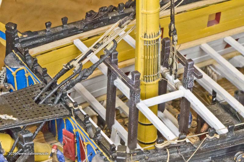
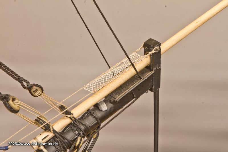
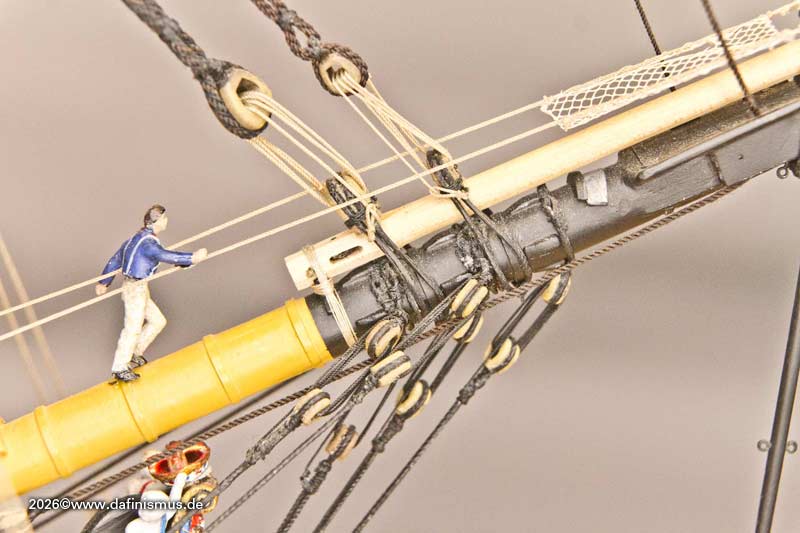
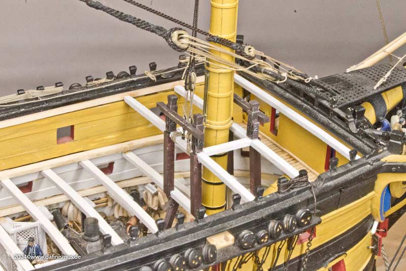
And now the lanyards for the stays fit too in the correct level (shown here with the old bitts still)

Image

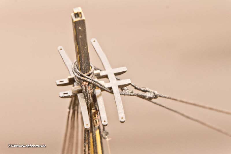
Steel still uses violin blocks on almost all the stays, whilst he has replaced all other violin blocks with standard double blocks. Most rigging instructions specify only thimbles and lashing at this point, but in my estimation, this is a later method of use.

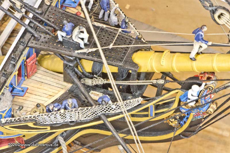
A distinctive feature of the main topmast stay and the preventer stays is, of course, that the topmast preventer stay is thrown over the actual topmast stay, but is then led under it in the eye so that it can be used for the staysails. Here I need to sort it out properly again to ensure that the two do not pinch each other.

Image

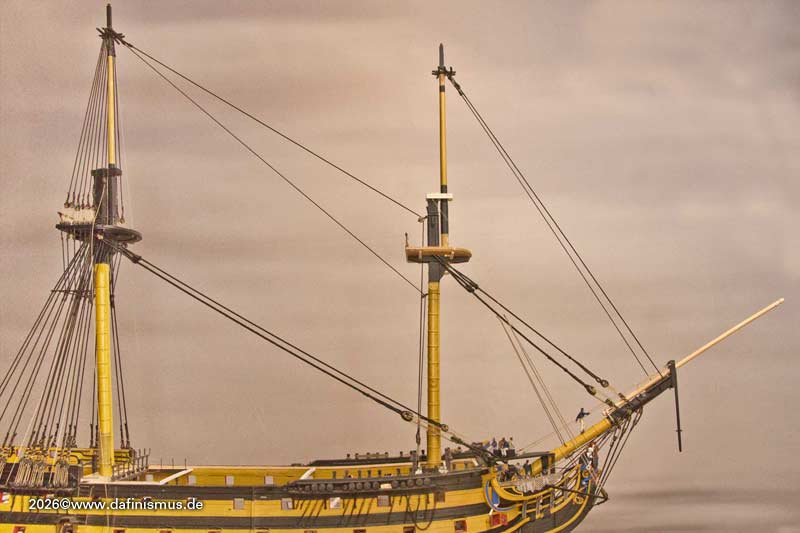
To throw the shrouds over the foremasthead, the stay block at the masthead must of course be removed; to do this, however, only the lashing on the rear need to be loosened.

Image

XXXDAn
To Victory and beyond ...
viewtopic.php?f=59&t=99050&start=60

See also our german forum for the age of Sail and History:
http://www.segelschiffsmodellbau.com
User avatar
dafi
Posts: 1002
Joined: Mon Mar 12, 2012 11:13 am
Location: Ludwigsburg/Germany
Contact:

Re: To HMS Victory and beyond

Post by dafi »

Funny things happen on the way to Victory. Why are there two double seats of ease on Mariners Walk? Any new findings from dafinistic investigations?

Image

...

Yep, because once you’re at the stays, you might as well join in with the fore topmast stay and the fore topmast preventer stay. Here too, the stays are crossed so that the preventer stay can be used as a rider for the staysails.

Image

Note: Don’t be surprised – I’ll fit the shrouds underneath later; to do that, I just need to loosen the lanyards at deck level :-)

The stays pass behind the bowsprite´s cap through the violin, with the forestay on the starboard side through the front hole and the backstay on the port side through the rear hole. There is a block with a sheave beneath each one. From there, both should run to their respective bolts on the knight heads.

Image

Somehow, I’ve always seen the lanyards inside the supporting pillars of the mariner walk; to do this, I placed the fore topmast stay in position with some overlap and marked the position of the pillar with a coloured thread so that the block cannot chafe.

Image

But it did look a bit odd, the way the rope was wriggling its way through behind it.

So I threaded a coloured string through again – once on the inside and once on the outside – and lo and behold...

Image

... unhooked the block from the knighthead and moved it outwards ...

Image

... and it actually makes more sense out there.

Then I’ll wrap the excess rope around the lanyard with half-hitches, just like in the original, but I won’t glue it yet, because that’s exactly what I need to undo before I can fit the topmast shrouds.

And you can also see why the two thrones aka seats of ease chairs had to be moved out of the way first – it’s all bloody cramped in here. When repositioning them, they’ll have to be 2 mm further out so that it fits.

XXXDAn
To Victory and beyond ...
viewtopic.php?f=59&t=99050&start=60

See also our german forum for the age of Sail and History:
http://www.segelschiffsmodellbau.com
User avatar
dafi
Posts: 1002
Joined: Mon Mar 12, 2012 11:13 am
Location: Ludwigsburg/Germany
Contact:

Re: To HMS Victory and beyond

Post by dafi »

And once you’ve started down that road, you have to see it through: after the bowsprit, it was finally the jib boom’s turn.

Years ago, I’d already prepared it to show the differences between plastic and wood.

Image

Image

Both times, the jib boom had the same dimensions and the same weight attached to it, but the difference is striking :-)


So, I finally got my little Proxxon mini-milling machine out again; I had to mill a hole for the heel lashing and two sheave holes into this jib boom, which has been waiting for its finish for so many years.

Image

The rear sheave serves to hoist the jib boom itself, the front one for the flying jib boom.

Image

It was a bit of a faff getting the sheaves to the right thickness, but pressing them down with one pair of tweezers and sliding them over the sandpaper with the other worked well in the end.

Image

Then attach the surprisingly thin stropp at the heel of the boom.

Image

Image

... and that’s it. And these are the four double stay assemblies currently fitted. Enjoy.

Image

Best regards, Daniel
To Victory and beyond ...
viewtopic.php?f=59&t=99050&start=60

See also our german forum for the age of Sail and History:
http://www.segelschiffsmodellbau.com
Post Reply

Return to “Works in Progress”