I'm not sure if this is the right sub-forum for posting this query but please feel free to let me know and/or move the thread!
I have recently taken up 3D model making using Blender and I am working on creating a model of the TDY jammer assembly as seen aboard ALASKA (CB-1) in 1945. I've noticed during my research that there are multiple external forms this jammer assembly could take depending (I assume) on date of install and where it was installed, etc.
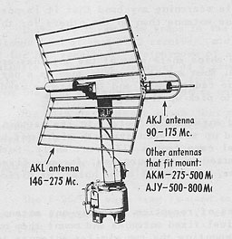
Later installations seem to universally make use of the 10AFJ antenna pedestal, equipped with the various types of reflectors available (10AKL, 10AKJ, 10AKM, 10AJY) which covered different frequency bands. Friedman's Naval Radar mentions that these reflectors could be swapped around by the ship's company "in about an hour" if required. Here is the later installation with 10AFJ pedestal and AKL/AKJ antennas installed back to back (I understand that the 10AFJ pedestal could rotate to bring the proper antenna to bear):
This excellent photo of WASHINGTON (BB-56) in late 1945 shows the later type installation on the small platform below the air defense level: http://navsource.org/archives/01/056/015645r.jpg
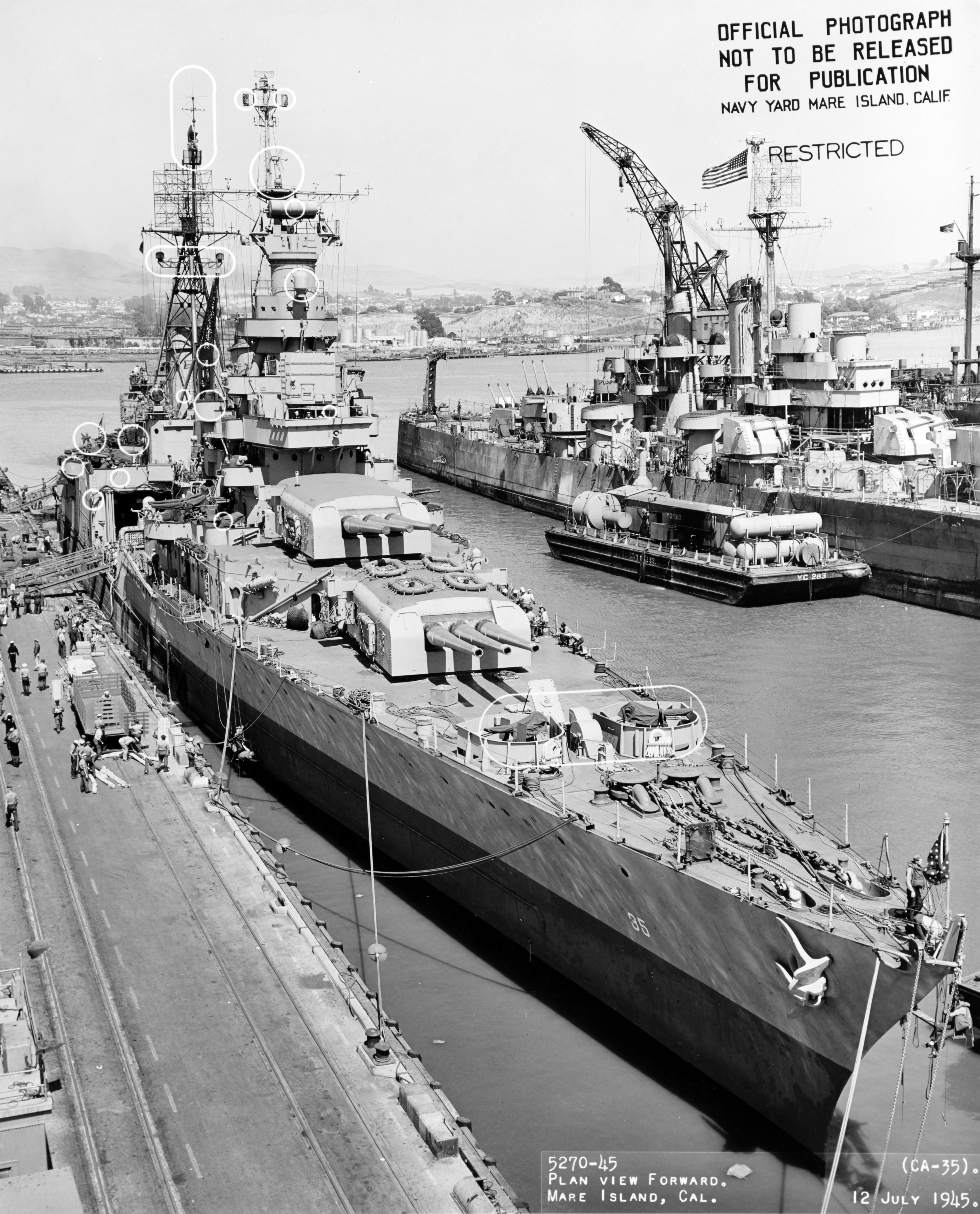
Also visible here is another TDY on the after side of the fire control tower about one deck level down, facing starboard and aft -- I assume this is a fixed installation designed to cover the obvious blind spot from the TDY on the front of the fire control tower. This 12 July 1945 photo of INDIANAPOLIS (CA-35) also shows the later TDY jammer at the foretop: http://www.navsource.org/archives/04/035/0403541.jpg
---
The later installation is very well documented and finding plans of it is straightforward -- what interests me for this project is what I think must be some sort of "early" or "interim" rotating antenna pedestal for the TDY seen on ships in late 1944. I have been able to identify a similar installation aboard ALASKA (CB-1), INDIANAPOLIS (CA-35) in early 1945, NORTH CAROLINA (BB-55) in 1945, and aboard MISSOURI (BB-63) during the surrender.
This photo of ALASKA in 1945 shows the TDY very clearly at the air defense level -- most artists have shown this as the later type installation: http://www.navsource.org/archives/04/1201/04020130a.jpg
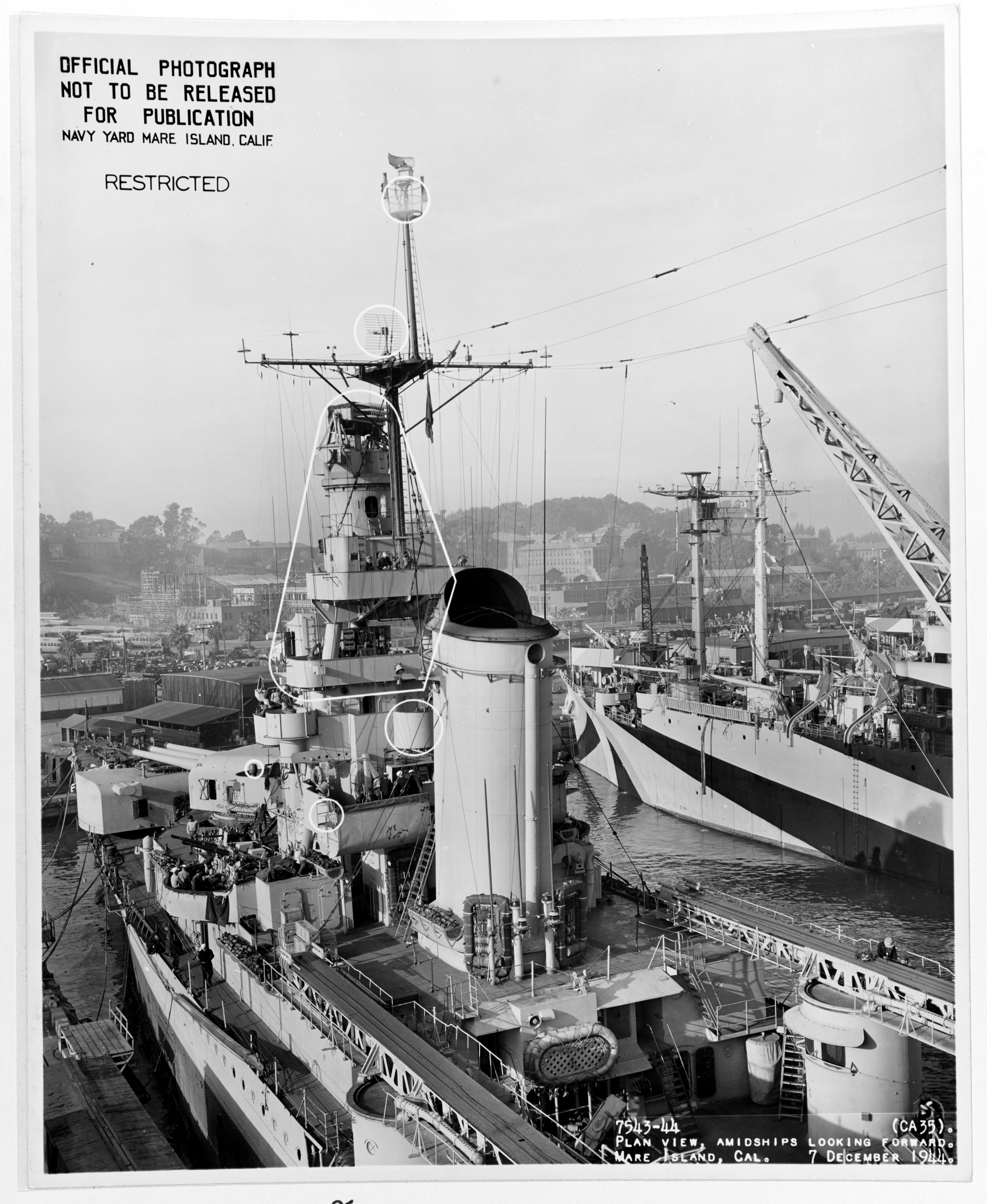
This photo of INDIANAPOLIS (19-N-76909) during the December 1944 yard period at Mare Island shows the early TDY at the foretop (it was later replaced with the 10AFJ pedestal and two reflectors): http://www.navsource.org/archives/04/035/0403521.jpg
This photo of MISSOURI at sea (80-G-376365) on 20 July 1945 while refueling shows the early type TDY bracketed below the air defense level forward: https://www.navsource.org/archives/01/016341c.jpg
Unfortunately there is no higher res version of 80-G-376365 I have been able to locate.
This photo of NORTH CAROLINA in July 1945 (80-G-469988) shows the same installation roughly even with the air defense level on a small bracket forward: http://navsource.org/archives/01/055/015545o.jpg It seems the pedestal base and the bracket are still present on the museum ship, with even the cabling for the unit running aft under the air defense level: https://i.redd.it/oue8ai86rqq31.jpg
---
Some key observations on the "early" type antenna pedestal are that the supporting stanchion for the antenna reflector is vertical without any tilt associated (like 10AFJ), and that only one reflector seems to be fitted. The pedestal does seem to rotate to "aim" the antenna down a specific bearing much like the 10AFJ pedestal later on (as evidenced by the photo of NORTH CAROLINA - 80-G-469908 where the antenna is slewed to port). The reflector on all of these early installations seems to be the larger corner reflector of the 10AKL antenna.
I believe the model of TDY fitted to ALASKA is the earlier type -- specifically because the reflector support appears as a square shape behind the reflector, instead of the circular support of the 10AFJ pedestal (in front elevation view, with the reflector facing the viewer bow-on).
Does anyone here have any information on this early type of TDY installation beyond what I've deduced above? I'm sure the unit was fitted to other ships (I just don't know which ones and discovering the above has been by happy circumstance). Any help is appreciated!
Also, a very good document describing operation of the TDY is available here: https://www.ibiblio.org/hyperwar/USN/re ... index.html
Cheers
Ian


