This is my first post in the Calling All Ship Fans forum - Not sure if anyone else here is building this ship at the minute (there seem to be quite a few models of it about), but it seems like the best place to post it.
Anyway, I'm currently scratchbuilding a 1/96 model of HMVS Cerberus (late 19th century turreted monitor/coast defence ship), based on the downloadable card model kit plans from Paper Shipwright. I'm building the model to represent the ship in the late 1880s with a single mast, additional light armament and shortened flying deck. The model is now about two-thirds complete in terms of major structural components, but there are still many small details to add.
Though I have plenty of reference material for the Cerberus (both the card model plans and photographs, plans and drawings from http://www.cerberus.com.au) there are still many details of the ship which I'm not sure about!
Any advice or information would be appreciated, hopefully this thread will be of use to anyone else building a model of this ship, whether scratchbuilt or from the card kit.
My first question is about the steam vent pipes next to the funnel. The various plans, drawings and models of the Cerberus seem to contradict each other about this. Some show a single large pipe forward of the funnel, others a pipe aft of the funnel and offset to one side (this is the configuration shown in the paper model) and others several small pipes around the funnel.
Which is correct, or was the layout of the steam pipes modified during the ship's life?
Calling all HMVS Cerberus breastwork monitor fans
Moderators: BB62vet, MartinJQuinn, Timmy C, Gernot, Olaf Held, Dan K, HMAS, ModelMonkey
-
Edward Pinniger

- Posts: 461
- Joined: Wed Jan 18, 2006 1:05 pm
- Location: UK
-
Avery Boyer

- Posts: 934
- Joined: Mon Apr 24, 2006 4:56 pm
- Location: Berks County, Pennsylvania
- Contact:
Ooh! Any pics? I have built the card model (Twice  ), but it isn't the easiest. I am contemplating building it in 1/350 out of yogurt container plastic ( ). I'd also like more info. Can anyone help us?
"It is best to remain silent and let others assume you are dumb than to speak up and remove all doubt"
http://nssavannah.wordpress.com/
http://nssavannah.wordpress.com/
-
Edward Pinniger
- Posts: 461
- Joined: Wed Jan 18, 2006 1:05 pm
- Location: UK
-
RickF
- Posts: 128
- Joined: Fri Oct 14, 2005 4:52 pm
- Location: Norfolk, UK
Not an expert, but I started building a 1:96 version using the paper model as a source for the plans.
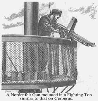
I'm building her with the full length flying deck, military mast mounted in the cowl vent with high position fighting top and Nordenfelt five barreled guns as secondary armament.
Unfortunately progress has come to a halt as other projects have taken over my life, but I hope to get back to her one day!
Rick

Black, white and buff - not grey!
-
Pieter
- Posts: 1608
- Joined: Sat Sep 17, 2005 9:19 am
Count me in. I've built the card model once in a simplified version (plastic in 1/700). After that I bought the Kombrig version, found out how many mistakes I'd made and started doing the kit. It is now complete and painted in it's subassemblies except the main hull. Still trying to figure out how to assemble the anchor derricks on the main hull without damaging them.
-
Edward Pinniger
- Posts: 461
- Joined: Wed Jan 18, 2006 1:05 pm
- Location: UK
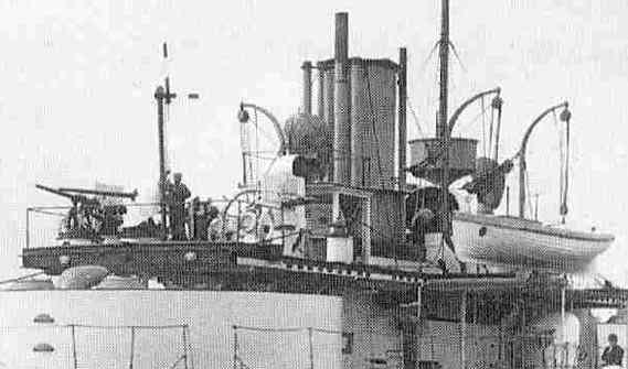
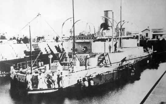
This photo appears to answer my question about the steam pipes: http://www.cerberus.com.au/fdeckbow.jpg
It seems that in addition to the pipe aft of the funnel and offset to one side (as in the paper model) there are two pipes forward of the funnel, one the same size as the aft one and the other shorter and narrower.
Another interesting detail visible in this photo is the signalling semaphore (the sailor is standing next to its base), and the searchlight platform (between the ventilator and the funnel) which seems to be missing from most plans and models of the ship, though it is shown on several photos. I believe that it is positioned above a skylight.
There's a lot of useful information in the Image Library at http://www.cerberus.com.au, including some good photos of the Nordenfelt guns which will be useful for anyone attempting to scratchbuild these.
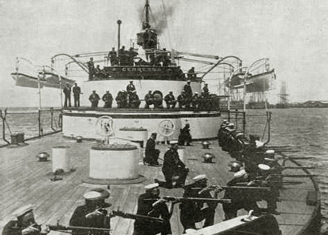
I have a question about this photo, http://www.cerberus.com.au/cerbdeckrifles.jpg - It clearly shows covers (grates?) on the forward skylights instead of the elaborate "faceted" glass covers usually seen. As most photos show the glass covers, I'm guessing that the solid ones were installed when at "action stations", to remove the danger from flying glass fragments?
As the glass covers look like they'll be a serious pain to scratchbuild, I'm definitely inclined to build the skylights with the solid covers as shown in the photo!
I also have a couple of questions about the single mast fitted to the Cerberus in its post-1885 fit:
- Was the mast fitted into the boiler air intake structure? The mast is fitted at the same location as this structure, but plans and photos do not clearly show what's at the bottom of it. The one photo I have shows what appears to be a large vent cowling in the position of the air intake, quite different to the original fitting which is a rectangular box with a cylindrical intake on top.
- Was the fighting top made of solid metal sheet, or open? It definitely looks solid in photos, but this could be due to a canvas spray shield? This contemporary drawing: http://www.cerberus.com.au/nord5intopcleancom.jpg shows a wire mesh structure with a wooden floor. (I think this is a generic representation of a fighting top and is not specifically meant to be the one on the Cerberus)
It seems that in addition to the pipe aft of the funnel and offset to one side (as in the paper model) there are two pipes forward of the funnel, one the same size as the aft one and the other shorter and narrower.
Another interesting detail visible in this photo is the signalling semaphore (the sailor is standing next to its base), and the searchlight platform (between the ventilator and the funnel) which seems to be missing from most plans and models of the ship, though it is shown on several photos. I believe that it is positioned above a skylight.
There's a lot of useful information in the Image Library at http://www.cerberus.com.au, including some good photos of the Nordenfelt guns which will be useful for anyone attempting to scratchbuild these.
I have a question about this photo, http://www.cerberus.com.au/cerbdeckrifles.jpg - It clearly shows covers (grates?) on the forward skylights instead of the elaborate "faceted" glass covers usually seen. As most photos show the glass covers, I'm guessing that the solid ones were installed when at "action stations", to remove the danger from flying glass fragments?
As the glass covers look like they'll be a serious pain to scratchbuild, I'm definitely inclined to build the skylights with the solid covers as shown in the photo!
I also have a couple of questions about the single mast fitted to the Cerberus in its post-1885 fit:
- Was the mast fitted into the boiler air intake structure? The mast is fitted at the same location as this structure, but plans and photos do not clearly show what's at the bottom of it. The one photo I have shows what appears to be a large vent cowling in the position of the air intake, quite different to the original fitting which is a rectangular box with a cylindrical intake on top.
- Was the fighting top made of solid metal sheet, or open? It definitely looks solid in photos, but this could be due to a canvas spray shield? This contemporary drawing: http://www.cerberus.com.au/nord5intopcleancom.jpg shows a wire mesh structure with a wooden floor. (I think this is a generic representation of a fighting top and is not specifically meant to be the one on the Cerberus)
-
RickF
- Posts: 128
- Joined: Fri Oct 14, 2005 4:52 pm
- Location: Norfolk, UK
-
RickF
- Posts: 128
- Joined: Fri Oct 14, 2005 4:52 pm
- Location: Norfolk, UK
I thought the site that I got the drawings from was the State Library of Victoria
http://sinpic.slv.vic.gov.au/cgi-bin/Pw ... &PID=29634
but they do not seem to be there now. However, I have them all on my PC, so if you want them, PM me with your e-mail address and I'll forward them.
Rick
http://sinpic.slv.vic.gov.au/cgi-bin/Pw ... &PID=29634
but they do not seem to be there now. However, I have them all on my PC, so if you want them, PM me with your e-mail address and I'll forward them.
Rick
Black, white and buff - not grey!

-
RickF
- Posts: 128
- Joined: Fri Oct 14, 2005 4:52 pm
- Location: Norfolk, UK
Regarding EP's post in the scratchbuilding thread:
The photo I posted (courtesy of http://www.cerebus.com.au) shows a view of the aft turret in the 1870s and is yet another illustration of the problems of how and what to include in a model for any period. There are doors over the turrret gunports and the officers heads are not fully enclosed. And, as EP says, the breastwork is black. It also show one of the skylights with the glass cover removed. I believe this was done when clearing for action, and a metal cover fitted
On the neverending topic of the davits, the following is an extract from the specification which now appears at:
http://www.cerberus.com.au/specification.pdf
Boats Davits and Other Fittings for Boats. To be in Number, Size, and Positionas shown upon the Drawings, or as mav be required, complete with Blocks, Chain Guys, Metal Sheaves, Topping Lifts, Slips, Crutches, Eye Bolts, and all other Fittings requisite for Raising, Lowering, Stowing, and Securing all the Boats. The Boats' Davits are to hinge and swivel at the Heel as may be directed.
This is signed by Reed, and while it doesn't prove that the davits where extendable, at least it shows he was thinking about it!
Rick
Black, white and buff - not grey!
-
Edward Pinniger
- Posts: 461
- Joined: Wed Jan 18, 2006 1:05 pm
- Location: UK
A couple more questions:
- Was the compass platform (on the aft deck) square or round? The card model has a round platform, but the only references sources I can find which show the compass platform (a contemporary engraving, and photos of the 1/48 model) both have a square platform.
- What are the three U-shaped fittings on the turret roofs? I assumed that these were vision ports, but the only photo I can find which appears to show this fitting: http://www.cerberus.com.au/cerbgunreplace2.jpg - shows a rounded object which looks more like a vent.
-
RickF
- Posts: 128
- Joined: Fri Oct 14, 2005 4:52 pm
- Location: Norfolk, UK
EP,
It looks round in this early photograph http://www.cerberus.com.au/AWM_300036.jpg
The fittings on the turrets are sighting hoods - one for each gun captain and one for the turret comander. I believe the sights were fitted to the forward edge of the turret, but only when at action stations. This plan shows the hoods.

They seem to have changed with the years, like so much else on the ship. There are also large round hatches? on the turret tops, as seen in the background here http://www.cerberus.com.au/awmP00952_002.jpg
It looks round in this early photograph http://www.cerberus.com.au/AWM_300036.jpg
The fittings on the turrets are sighting hoods - one for each gun captain and one for the turret comander. I believe the sights were fitted to the forward edge of the turret, but only when at action stations. This plan shows the hoods.
They seem to have changed with the years, like so much else on the ship. There are also large round hatches? on the turret tops, as seen in the background here http://www.cerberus.com.au/awmP00952_002.jpg
Black, white and buff - not grey!
-
Edward Pinniger
- Posts: 461
- Joined: Wed Jan 18, 2006 1:05 pm
- Location: UK
Many thanks for the info! There seems to be a lot of useful information on the plan you posted - it shows a number of features not shown in any other references I have, such as the central turret shafts actually extending up through the roof of the turret and apparently attached to the flying deck. Is there any way to obtain a higher-resolution copy?
I also wasn't aware that the floor of the turrets was actually below the level of the breastwork deck (lucky I didn't attempt to build any interior detail in the turrets on my model - their floor is at deck level!)
I have to say that the compass platform (between the two skylights) definitely looks more square (or rectangular) than round to me in that photo, but that's just my opinion (and it's hard to tell for sure from such a small image)
-
RickF
- Posts: 128
- Joined: Fri Oct 14, 2005 4:52 pm
- Location: Norfolk, UK
If you are building Cerberus with a shortened flying deck, I think the compass was removed from the deck and may have been installed on the bridge by then. It was replaced by a companionway installed between the two skylights - not sure of the date. The images "Mustering at the Stern", "Aft Turret" and "Sunday Divisions" ( http://www.cerberus.com.au/image_librar ... magewindow ) clearly show this, together with the removable skylight covers.
The plan of Cerberus came from http://home.vicnet.net.au/~maav/cerbplan.htm
There is a better cross-section of the turret on this page: http://www.cerberus.com.au/alterations.html
You are welcome to share any of the drawings I have accumulated - I've sent you a PM.
Rick
The plan of Cerberus came from http://home.vicnet.net.au/~maav/cerbplan.htm
There is a better cross-section of the turret on this page: http://www.cerberus.com.au/alterations.html
You are welcome to share any of the drawings I have accumulated - I've sent you a PM.
Rick
Black, white and buff - not grey!
-
David Gatt

- Posts: 225
- Joined: Sun Oct 09, 2005 4:22 pm
- Location: Melbourne Australia
-
brad

- Posts: 169
- Joined: Tue Aug 18, 2009 7:09 pm
- Location: Adelaide, Australia
Re: Calling all HMVS Cerberus fans
It's a crying shame to see this poor thing being treated in this way.
I have just purchased the 1/350 resin kit of Combrig which is, really, the basis of a kit rather than the whole - and it's only a waterline version, as well. Still better than nothing and something a little different to build.
All I have to do now is work out which period I want the model to represent.
cheers,
bj
Happy to help with research & assistance regarding medals to Australians.