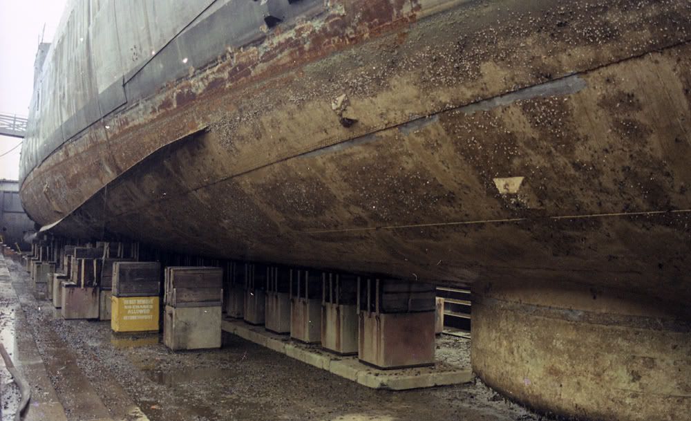
Here is a Hull photo of the USS Cassin Young DD-793 (Fletcher Class) taken during a drydocking period in 1979-80 that i came across. Credit for the photo is: National Park Service photo, Boston National Historical Park. Of note are the large number of rivets. I had always thought she was a welded ship.
Also, the sonar dome "appears" to be longer than what I have seen before. Did she have another dome incorporated? Or is the camera playing tricks on my eyes?
OK, for todays update, I THINK I'm done with the lower hull as far as modifications go......except for the sonar dome.
I have completed the Condenser Intakes and Discharges plus an assortment of other discharges, that I can't place names to.........yet. All were done with aluminum or brass pipe. I have kind of a patchwork of primer due to all the other alterations.
The Belly Intakes:
Intakes and discharges:
Forward Eng Room Condenser intakes and discharges:
I've been preparing the Brass risers as the stand. Stupid stand is harder than I thought.
Barnacles.... ....one by one. They would cover up a whole host of errors.
One thing I actually thought about after I started this...........was to "plate" the whole hull with beer can aluminum. The reason for this isn't to "oil can" but to show the really "obvious" overlapping on the real thing. I think the "problem" with that would be it's not that ovbvious from a distance.
Steve,
You're doing a great job; I am very impressed!!
Keep up the good work; I'm following your progress with a lot of interest and anticipation.
best,
Bruce
Bruce
OSC USN-Ret
Currently on the building ways:
1/144 USS Stevens DD-479
1/144 USS Cook Inlet AVP-36
1/144 USS Walke DD-416
1/144 USS Blue DD-387
1/144 USS Preble DDG-46
I've been DIW trying to get a grip on my "Base" plan.
Brass Riser update.
I've learned more about brass lamp risers than I ever wanted to know. They come in different shapes and sizes, anodized and not. I chose non-anodised. The only place I could find them in my area was at a lamp store.
The risers that I chose have a "specialty" thread to them. 1/4" 28 and not the standard 1/4" 20. That took some looking to find.
I now have the nuts and bolts hardware, and I have the brass tubes. These tubes fit snugly together. "Plan A" I will mount the larger one inside the hull from keel to deck to provide a solid support for the smaller tube to slide into. (by the way I have one set of risers for "Plan B" that I cut off the threaded male end and drilled out the barrel that will allow the smaller tube to fit into. "Plan C" will be to sand down the threads on the male end and slide the smaller tube onto it tightly. This gives me several options to work with)
Be careful using USS Cassing Young's sonar dome. It is upgraded version mounted in 50'. Initially sonar dome was smaller and placed more forward (just before first 5' gun). We had a discussion here on Fletcher Fans forum regarding a sonar. Later on I will send you some additional data.
After almost 2 months of working on my Fletcher, I have just yesterday glued my first two kit pieces together.
I have joined the two hull halves together. Liquid glue, doublers, Kit Hull braces, and then the not so pretty interior contraption for the holding of the display stand. Half a bottle of CA on that. Not pretty inside but solid as a rock.
I was careful with all the joining being done from inside so there is very little exterior cleanup. The seam does need a little sanding.
Still have some fine details to work out. Bic pen is the white plastic outer sleeve mounted securely inside the hull. The larger dia brass tube slides snugly inside the plastic Bic tube, will be CAed permanently. Small brass tube will be either Option 1. inserted INSIDE the Lamp Riser where i cut off the male threads and drilled it out. or Option 2. Slid OVER the sanded off male threads on the riser. This will be able to fit snugly inside the larger brass tube and yet be removable.
A solid "no shake" stand. I ground down the male threads on the Brass Riser. Fitted and CAed the smaller brass tube to that end of the riser. The larger brass tube is CAed into the White Bic plastic pen........which is very solidly attached to the inside of the hull.
You will note from the photo that I had thoughts of drilling out the Brass Riser and either slipping in the smaller tube or a long bolt. Went through several brass risers in this testing process.
I THINK I have something that will be solid, yet allow me to remove the hull from the stand. If i had not wanted to make the stand removable i would have omitted the smaller tube. It would then have fit onto the male elnd of the riser.
Hi Steve,
Great work so far. I am at about the same stage as you on the same model. The only difference is that I am changing it to a late war representation of the Kidd with the square bridge and extra armament, which I intend to scratchbuild. That will give me enough extra work to do, so I am leaving the the plating stretchmarks off my agenda!
I have also been looking for information on the underwater inlets and outlets and have only some pics of the Kidd and those in the Fletcher thread on this site. Your work is going to help me a lot.
Regarding the echo sounder bulb under the hull, Bob Steinbrun fitted the correct version (1945) on his model, which was apparently able to be withdrawn into the seachest in the hull next to the keel. I have a pic of his model and as far as I can see it looks nothing like the pics we have seen so far. Maybe he could be approached for a resource for this. It would be a pity for you to be unable to model it for lack of info.
Best Regards,
Peter
OK, one last "Stand" photo and I'm back to work on the ship.
I have attached a "Temporary" build stand. The display stand later. It's not hard to see the belly intakes sitting elevated like this. No brass parts have been CAed as of yet, but the photo showing it being lifted shows that the fit is tight and it's not really going anywhere. I had to cut down my bolts as I recessed the heads into the wood base.
This stand/base has taken me an abnormally long time since I've never made a ship stand before. I had to spend the time now as once the deck is in place............I'm out of options. At least now i have the steps down. Next ones will be much simpler as far as time is concerned.
Short update. While inspecting the main deck "sitting" in place on the hull, my attention kept going to the midship 20mm gun tubs (as seen in the above photo) that are molded into the hull. They HAD to go. I cut them out.........repairing the damage and am building new much thinner tubs out of thin styrene. Photos later.
Finally an update with pictures. I got the waist 20mm Gun Tubs done. I scraped off the old thick ones, sanded, and polished the deck. I built the tubs out of thin styrene.
References are all over the page on just what these things look like. I checked the plans and i checked photos. Those drain holes are all over the place.......reference wise. What I have done is come up with what looks plausible according to the references that i do have. They are certainly better than the originals. I'm happy with them.
First photo shows the sanded and polished deck along with the tub pieces.
The finished product. The rib around the tub "appears" to be a stiffening piece. You can just about see the old molded tub laid on the far side inside the new tub. Little out of focus there.
Looks pretty close to me ... good work, but you may want to cutout some more of the lower part of the bulwark. And yes the 20-mm (and 40-mm) splinter bulwarks did vary quite a bit from builder to builder and repair yard. But generally speaking, the first few Fletchers were built to the Gibbs and Cox plans and were close in "styles" at both BIW and Federal. But, there were still minor differences. In 1/700 scale this isn't even noticeable ... but in these larger scales they can be.
First two images are Fletcher on 26 June 1942 at Federal SB&DD.
The third image is O'Bannon on 21 June 1942 at Bath Iron Works.
It also looks like the top lip was rolled over on them. You might want to put a piece of half round around the top. Good looking build so far. You're putting more into it than I would want to.
Any ship larger than a Destroyer is a waste of metal.
I don't know that it will be that it will be that noticeable. If you have plans to "clutter-up" your model to look "lived on", some strategically located "stuff" (rope, etc) could hide the missing drains. I didn't post a view of the O'Bannon or Nicholas looking at this bulwark from the aft direction, because I couldn't find a good view. But, I went back and found an aft view of this area on the Chevalier (DD-451) that shows that it was made much as Fletcher's bulwark. Basically you have the forward end of the splinter/spray bulwark done the way the early BIW Fletchers were made, the only difference from those ships are the additional drains on the aft side. Other views of these ships in the South Pacific show no changes to this bulwark that I can determine.