Calling all USS Hornet CV-8 fans
Moderators: BB62vet, MartinJQuinn, Timmy C, Gernot, Olaf Held, Dan K, HMAS, ModelMonkey
-
j leyland
- Posts: 129
- Joined: Thu Feb 17, 2005 2:54 pm
Re: Calling all USS Hornet CV-8 fans
The HP resin kit of the CV-5 class has an accurate hull and is quite good on basic shapes. The Trumpeter deck is better detailed and the HP deck is in three pieces, but they are engineered so that the joint can be hidden by arresting gear cables if you don't mind one crossing the fwd elevator (it did, but in actual practice it was usually pulled back and fixed to the first tie down strip aft of the elevator so that the elevator could be used). I used this kit as the basis of a Dolittle Raid diorama and was happy with the basic shapes.
-
wildspear

- Posts: 84
- Joined: Thu Apr 05, 2007 10:52 am
- Location: MI/ usa
- Contact:
Re: Calling all USS Hornet CV-8 fans
John and Sixman,
When makeing the templates for your hull jig, how is the Webb Warships plan different than the book I'm getting from Maryland Silver Company? Do either one of you have some scans of the templates you used? Any help you be most helpful, I'll be starting my build in Jan 2010.
When makeing the templates for your hull jig, how is the Webb Warships plan different than the book I'm getting from Maryland Silver Company? Do either one of you have some scans of the templates you used? Any help you be most helpful, I'll be starting my build in Jan 2010.
-
wildspear
- Posts: 84
- Joined: Thu Apr 05, 2007 10:52 am
- Location: MI/ usa
- Contact:
Re: Calling all USS Hornet CV-8 fans
Dick,dick wood wrote:Hi all:
I am in the process of building the Trumpter Hornet, and I have a question concerning the funnels. Did they have splitters, and if they did can anybody give me a descriptopn so I can install them?
Thanks in advance.
Did you ever find out info about the splitters? I'm starting my build in Jan 2010 and the info would be most helpful.
-
wildspear
- Posts: 84
- Joined: Thu Apr 05, 2007 10:52 am
- Location: MI/ usa
- Contact:
 Re: Calling all USS Hornet CV-8 fans
Does anyone know where I can get a cross section at the frames/bulkheads? I want to try a plank hull instead of correcting the hull I have in my trumpeter kit.
-
dick wood

- Posts: 72
- Joined: Mon Jan 10, 2005 6:21 pm
- Location: Westerville, Ohio
- Contact:
Re: Calling all USS Hornet CV-8 fans
Wildspier:
No I did not so I will use my best guess on this one.
No I did not so I will use my best guess on this one.
Dick Wood
-
Michael Vorrasi

- Posts: 476
- Joined: Sun May 08, 2005 11:15 am
- Location: Brooklyn NY USA
Re: Calling all USS Hornet CV-8 fans
Dick, If you can elaborate, that might help me understand what you are trying to figure out. If you mean are there separate uptakes inside the funnel, yes, there are three separate uptakes inside the island's big single funnel housing, but what are you trying to convey with the term splitter?dick wood wrote:Hi all:
I am in the process of building the Trumpter Hornet, and I have a question concerning the funnels. Did they have splitters, and if they did can anybody give me a descriptopn so I can install them?
Thanks in advance.
Mike

-
Dick J

- Posts: 1991
- Joined: Mon Aug 06, 2007 6:29 pm
Re: Calling all USS Hornet CV-8 fans
Mike,
I don't believe he is referring to the three circular uptakes. He is referring to the possibliity of divisions within each of the uptakes. If you look at some of the cruiser and destroyer funnels, the interior is "split" into a number of chambers, usually reflecting the number of boilers serviced by that particular funnel. In other words, each boiler uptake is a distinctly separate tube all the way to the top of the stack. These divisions are often masked in photos by the "mesh" clinker screens over the top.
I don't believe he is referring to the three circular uptakes. He is referring to the possibliity of divisions within each of the uptakes. If you look at some of the cruiser and destroyer funnels, the interior is "split" into a number of chambers, usually reflecting the number of boilers serviced by that particular funnel. In other words, each boiler uptake is a distinctly separate tube all the way to the top of the stack. These divisions are often masked in photos by the "mesh" clinker screens over the top.
-
Michael Vorrasi
- Posts: 476
- Joined: Sun May 08, 2005 11:15 am
- Location: Brooklyn NY USA
Re: Calling all USS Hornet CV-8 fans
Thanks Dick J. I now understand what he is after. Unfortunately, the plans might not show that internal detail, but I'll give it a look tonight. The Yorktowns had nine boilers and three uptakes, but I need to check how each was fed. The after-most uptake exhaust is slightly smaller than the two ahead of it, so I'm not sure if the distribution was even to all three. I'll do some checking and report back. I have a good close up of Yorktown that, if memory serves, shows the funnel details well.Dick J wrote:Mike,
I don't believe he is referring to the three circular uptakes. He is referring to the possibliity of divisions within each of the uptakes. If you look at some of the cruiser and destroyer funnels, the interior is "split" into a number of chambers, usually reflecting the number of boilers serviced by that particular funnel. In other words, each boiler uptake is a distinctly separate tube all the way to the top of the stack. These divisions are often masked in photos by the "mesh" clinker screens over the top.
Mike
-
Dick J
- Posts: 1991
- Joined: Mon Aug 06, 2007 6:29 pm
Re: Calling all USS Hornet CV-8 fans
Mike,
I am fairly confident that each uptake serviced three boilers. The forward six boilers produced the steam which was then run through the after three, the "superheaters", which boosted the pressure. That could explain the difference in uptake size.
I am fairly confident that each uptake serviced three boilers. The forward six boilers produced the steam which was then run through the after three, the "superheaters", which boosted the pressure. That could explain the difference in uptake size.
-
Michael Vorrasi
- Posts: 476
- Joined: Sun May 08, 2005 11:15 am
- Location: Brooklyn NY USA
Re: Calling all USS Hornet CV-8 fans
Dick J, you are correct. Checked the plans. The first three, boilers 1 to 3, feed the first uptake, the next three feed the center one and the last three feed the aft uptake. The superheater set (boilers 7 through 9) would have differing exhaust characteristics, and this would explain why the aft uptake exhaust port is slightly smaller.Dick J wrote:Mike,
I am fairly confident that each uptake serviced three boilers. The forward six boilers produced the steam which was then run through the after three, the "superheaters", which boosted the pressure. That could explain the difference in uptake size.
Back to the question at hand from Dick Wood. Splitters. A qualified maybe. The plans do not show internal details of the uptakes. The overhead plan of the funnel caps show a six segmented clinker screen framework, aligned with one frame running through each cap directly port to starboard, and then an even x laid atop to form the pizza pie. Now is where the "maybe" comes in. There is a fairly wide fore and aft aligned "something" running through the center of each cap opening, below the clinker screen frames. It could be a splitter, dividing each uptake into even left and right sections, or it could be just a structural girder that does not run down into the funnel uptake. Cannot draw a conclusion from the plans. The photo I had in mind did not help. On a model, it might not matter that much, but there is definitely something in there and it is a couple of feet wide too. If someone placed something in there like fore & aft splitters, nobody could say it was wrong (yet!).
(PS, did you get the photos I sent you of the Big E's forward 1.1" Quad and director from her Santa Cruz battle damage report? Still puzzling over the possible location of where CV-8 had her director for this tub. Doubtful they would have mounted a manual one at that stage in the war, especially when CV-6 got a director at the same time. I'm leaning to it possibly being on the port side stub catwalk left under the fwd. flight deck ramp. From the underside, the only close shot I have of it, that little catwalk stub was beefed up, as if holding something weighty. It is not open grating as the rest. What do you think?)
Mike
-
Dick J
- Posts: 1991
- Joined: Mon Aug 06, 2007 6:29 pm
Re: Calling all USS Hornet CV-8 fans
Hi Mike,
I got the photos, but I still can't locate Hornet's 1.1 director. However, one thing to consider is the difference between the two. Enterprise only cut out the middle of the catwalk. Hornet lost almost all of it. could the director somehow have been mounted behind the tub, and the catwalk was removed to give greater lines of sight? Attaching it to one of the stubs wouldn't explain why the catwalk on the other side of the tub was removed. Beyond that, I have no idea.
I got the photos, but I still can't locate Hornet's 1.1 director. However, one thing to consider is the difference between the two. Enterprise only cut out the middle of the catwalk. Hornet lost almost all of it. could the director somehow have been mounted behind the tub, and the catwalk was removed to give greater lines of sight? Attaching it to one of the stubs wouldn't explain why the catwalk on the other side of the tub was removed. Beyond that, I have no idea.
-
wildspear
- Posts: 84
- Joined: Thu Apr 05, 2007 10:52 am
- Location: MI/ usa
- Contact:
 Re: Calling all USS Hornet CV-8 fans
I start my CV-8 build tomorrow and I'm planning on doing a plank hull (trying at lest) I still need a side veiw showing where the frames are. Hopfully in scale (1/350) but at lest with measurements so if anyone can help me I would be most grateful.
-
Michael Vorrasi
- Posts: 476
- Joined: Sun May 08, 2005 11:15 am
- Location: Brooklyn NY USA
Re: Calling all USS Hornet CV-8 fans
You can find the hull cross sections in both the Webb Warships CV-5 plans (from The Floating Drydock) and in the Maryland Silver Co. CV-5 plan set and CV-5/6/8 blueprint books, although you will have to do some converting to the proper scale. You will not find that kind of detail on line because it is generally too big and the measurement figures too small and detailed to scan to a digital file.wildspear wrote:I start my CV-8 build tomorrow and I'm planning on doing a plank hull (trying at lest) I still need a side veiw showing where the frames are. Hopfully in scale (1/350) but at lest with measurements so if anyone can help me I would be most grateful.
-
Michael Vorrasi
- Posts: 476
- Joined: Sun May 08, 2005 11:15 am
- Location: Brooklyn NY USA
Re: Calling all USS Hornet CV-8 fans
Dick J wrote:Hi Mike,
I got the photos, but I still can't locate Hornet's 1.1 director. However, one thing to consider is the difference between the two. Enterprise only cut out the middle of the catwalk. Hornet lost almost all of it. could the director somehow have been mounted behind the tub, and the catwalk was removed to give greater lines of sight? Attaching it to one of the stubs wouldn't explain why the catwalk on the other side of the tub was removed. Beyond that, I have no idea.
Dick J, take a look at this shot. The catwalk stub seems to have something built atop it of a more substantial structural nature, to hold added weight that a catwalk would normally not have on it. In fact, it looks to be stepped up on top of the remaining stub. That is what has me sniffing around this location. I don't think it could be situated behind the gun mount as half the mount is already under the flight deck, and fields of view for good fire control would have been impossible. I cannot account for it at any other possible location. Another possibility is that the bow mount was slaved to the number two director that sat in the cylindrical tub in front of the island, as that director would also have a good field of view for the bow tub's field of fire. Of course, that would require the director's normal mount, the number two 1.1" quad on top of the forward clipping room, to also be firing at the same target, or else switched over to the number one director in the starboard catwalk just aft of the five 20mm tubs there. I'm leaning in favor of the spot in this photo as having the director sitting on top of it. OTOH, I could be all cross-eyed and looking at it and seeing something that isn't there, like maybe that is a platform that is actually behind the stub catwalk to service the DF loop. A definite possibility! Need to find better photos to confirm this theory, but I put it out there for all to consider. (Sidebar: of interest in this photo, note the stowed DF loop antenna. I've seen it extended in other photos. She had one under the starboard aft flight deck corner as well, for 360 degrees coverage.)
More on CV-8's AA batteries. I reviewed the old Floating Drydock Battle Damage Report for Hornet at Santa Cruz, and reviewed the rarely reproduced shots from Pensacola taken before the famous photo of Hornet about to be struck by the diving Val. My copy has a particularly clean copy of the photo. I can clearly make out seven distinct dark blobs signifying a 20mm gun mount alongside the starboard island, and the location of the eighth is in front of these, and a bit fuzzy in this shot, but I've already verified that eighth one in another shot, so eight 20mm alongside the island is confirmed. The locations are one in front of her original four, and three aft of the original four with splinter mats or plates along the railings for these. The splinter shields for the four originals remained in place (I can see the curved ends in an overhead photo from Santa Cruz), and were added to with the mats/plates. Now, just what was that pesky antenna on CV-5 and 8 for...the hunt continues...!
Mike
-
Dick J
- Posts: 1991
- Joined: Mon Aug 06, 2007 6:29 pm
Re: Calling all USS Hornet CV-8 fans
Mike,
A director in this location would suffer as much of an obstructed view as would one behind the tub. The most likely explanation for the structure on the catwalk is the DF loop you referenced. The structure is the DF operating station. Using the director for #2 1.1 would introduce a paralax issue due to the distance between the gun and the director. Paralax can be compensated for in more complex systems, but in this case, the complexity would probably be beyond the rudimentary 1.1 director. A director behind or beside the bow tub would be able to target low fliers, such as torpedo planes working on an anvil attack. (The reason for the bow mount in the first place.) You are correct in that such a director would be totally obstructed for high elevation targets. The lack of other good locations for the director was the reason for the scary location on Enterprise. When CV-6 was modernized, The new tub was lower and off-center (but the cut in the catwalk was still centered - it was needed for the original higher gun and tub but not needed for the lower tub) allowing the director to be placed beside it.
A director in this location would suffer as much of an obstructed view as would one behind the tub. The most likely explanation for the structure on the catwalk is the DF loop you referenced. The structure is the DF operating station. Using the director for #2 1.1 would introduce a paralax issue due to the distance between the gun and the director. Paralax can be compensated for in more complex systems, but in this case, the complexity would probably be beyond the rudimentary 1.1 director. A director behind or beside the bow tub would be able to target low fliers, such as torpedo planes working on an anvil attack. (The reason for the bow mount in the first place.) You are correct in that such a director would be totally obstructed for high elevation targets. The lack of other good locations for the director was the reason for the scary location on Enterprise. When CV-6 was modernized, The new tub was lower and off-center (but the cut in the catwalk was still centered - it was needed for the original higher gun and tub but not needed for the lower tub) allowing the director to be placed beside it.
-
Fred-Branyan
Re: Calling all USS Hornet CV-8 fans
Hornet model builders
I have over 300 photos of the ship and its planes, which I have been collecting for some time due to the fact my father was on the ship for its entire career. I have separated some of them into a collection intended for model builders so that the camo scheme can be done correctly and that also includes closeup details. I have a similar collection for its planes through Midway that includes closeups of the dual 30 cal MG mounts for the SBD/TBD planes. Some of the ship photos are already on maritimequest, I can put them on a CD for anyone who is interested. I also have some you tube footage saved that proves the existence of a wide dark stripe running the length of the flight deck on the starboard side with the B25s on the deck, and that the wide white inboard stripe for the Doolittle launch actually had narrow black stripes on either side of it.
Fred Branyan
fredb1948@aol.com
-
Michael Vorrasi
- Posts: 476
- Joined: Sun May 08, 2005 11:15 am
- Location: Brooklyn NY USA
Re: Calling all USS Hornet CV-8 fans
Dick, considering all your thoughts and observations, I was looking at the CV-6 photos agaim, and was struck by how small the director tub was in relationship to the modified cloverleaf shaped gun tub itself. I don't think that little director tub on CV-6 could hold the directors of the type Hornet used for her original four 1.1" mounts. If a newer smaller director was used in Hornet for #5 1.1" mount, it is quite possible that it could fit inside one of the outer cloverleaf "lobes" in the main tub. Think this might be a possibility? Take a look at these comparisions between CV-8 and CV-6. Those wing lobes might fit. Only question is would the director be in the line of fire if the mount is trained that way. I think the director might be situated low enough to clear the barrels (but it might be noisy!) If one were to trace the circle formed by the added middle lobe, anything outside that circle would be clear of the gun mount, so it is a possibility. The only other alternative, and one I think unlikely and retrograde, was that number 5 mount was completely manual.Dick J wrote:Mike,
A director in this location would suffer as much of an obstructed view as would one behind the tub. The most likely explanation for the structure on the catwalk is the DF loop you referenced. The structure is the DF operating station. Using the director for #2 1.1 would introduce a paralax issue due to the distance between the gun and the director. Paralax can be compensated for in more complex systems, but in this case, the complexity would probably be beyond the rudimentary 1.1 director. A director behind or beside the bow tub would be able to target low fliers, such as torpedo planes working on an anvil attack. (The reason for the bow mount in the first place.) You are correct in that such a director would be totally obstructed for high elevation targets. The lack of other good locations for the director was the reason for the scary location on Enterprise. When CV-6 was modernized, The new tub was lower and off-center (but the cut in the catwalk was still centered - it was needed for the original higher gun and tub but not needed for the lower tub) allowing the director to be placed beside it.


Mike
-
Michael Vorrasi
- Posts: 476
- Joined: Sun May 08, 2005 11:15 am
- Location: Brooklyn NY USA
Re: Calling all USS Hornet CV-8 fans
Fred,Fred-Branyan wrote:Hornet model builders
I have over 300 photos of the ship and its planes, which I have been collecting for some time due to the fact my father was on the ship for its entire career. I have separated some of them into a collection intended for model builders so that the camo scheme can be done correctly and that also includes closeup details. I have a similar collection for its planes through Midway that includes closeups of the dual 30 cal MG mounts for the SBD/TBD planes. Some of the ship photos are already on maritimequest, I can put them on a CD for anyone who is interested. I also have some you tube footage saved that proves the existence of a wide dark stripe running the length of the flight deck on the starboard side with the B25s on the deck, and that the wide white inboard stripe for the Doolittle launch actually had narrow black stripes on either side of it.
Fred Branyan
fredb1948@aol.com
I would be absolutely thrilled to obtain these. Please send details via PM or e-mail.
Mike
Mike
-
Dick J
- Posts: 1991
- Joined: Mon Aug 06, 2007 6:29 pm
Re: Calling all USS Hornet CV-8 fans
It is possible, I think, that the director was in the "side-lobe" of the tub. It probably wouldn't be much noisier than for the gun crew itself. Given a choice of sides, I would think the starboard side to be the optimal one. (The other 1.1's were to starboard and the low ones could have their port-side arcs masked by aircraft on the flightdeck, so improving the bow gun's arcs to port would make the most sense.) Of course, logic isn't proof. Friedman indicated that the bow tubs didn't have directors, but obviously that wasn't correct for Enterprise. Without more information, Hornet's config is still "best guess."Michael Vorrasi wrote:Dick, considering all your thoughts and observations, I was looking at the CV-6 photos again, and was struck by how small the director tub was in relationship to the modified cloverleaf shaped gun tub itself. I don't think that little director tub on CV-6 could hold the directors of the type Hornet used for her original four 1.1" mounts. If a newer smaller director was used in Hornet for #5 1.1" mount, it is quite possible that it could fit inside one of the outer cloverleaf "lobes" in the main tub. Think this might be a possibility? Take a look at these comparisions between CV-8 and CV-6. Those wing lobes might fit. Only question is would the director be in the line of fire if the mount is trained that way. I think the director might be situated low enough to clear the barrels (but it might be noisy!) If one were to trace the circle formed by the added middle lobe, anything outside that circle would be clear of the gun mount, so it is a possibility. The only other alternative, and one I think unlikely and retrograde, was that number 5 mount was completely manual.
-
MartinJQuinn

- Posts: 8559
- Joined: Tue Jan 11, 2005 1:40 pm
- Location: New Jersey
Re: Calling all USS Hornet CV-8 fans
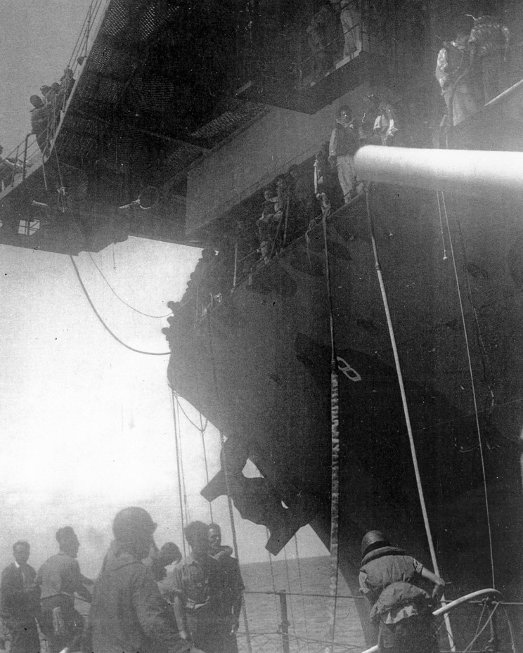
Got these pictures sent to me by Fred Branyan, who got them via Michael at Maritime Quest, who got them from a fellow named Tom Horn (whew!). Fred's Dad served on Hornet (and then Hancock), so he's been collecting photos of CV-8 for quite some time (refer to the post a few before this). These photos are all from the Battle of Santa Cruz, after Hornet had been attacked and disabled, around the time Northampton attempted to tow her to safety.
Other than the last photo showing the Hornet under attack, I don't recall ever seeing these photos before. The first and second photos clearly shows the 1.1 gun mounted on the bow. Fred has examined a high resolution verison of this photo, and no director seems to be associated with this mount.
Thank you Fred and Micheal for giving me permission to post these photos. Fred said he hopes these are of use to anyone building a model of CV-8.
Thank you Fred and Micheal for giving me permission to post these photos. Fred said he hopes these are of use to anyone building a model of CV-8.
Martin
"Tomorrow is the most important thing in life. Comes into us at midnight very clean. It's perfect when it arrives and it puts itself in our hands. It hopes we've learned something from yesterday." John Wayne
Ship Model Gallery
"Tomorrow is the most important thing in life. Comes into us at midnight very clean. It's perfect when it arrives and it puts itself in our hands. It hopes we've learned something from yesterday." John Wayne
Ship Model Gallery