So, according to the plans in the new CW#33 book, a "composite FC" radar was installed 3/42 aboard Lex.. I am familar with the MK-3 and MK-4 FC, but these antenna's dont resemble the one on CV-2. So does anybody want to guess on this particular FC Mark, and better yet, any reference photo's of the antenna? Im sure there will be alot of discussion regarding this book!
Jerry Phillips
Calling all USS Lexington CV-2 fans
Moderators: BB62vet, MartinJQuinn, Timmy C, Gernot, Olaf Held, Dan K, HMAS, ModelMonkey
-
Dick J

- Posts: 1991
- Joined: Mon Aug 06, 2007 6:29 pm
Re: Quick review: CW #33 USS Lexington
Thanks to this book, I now have better views of the starboard-side camo pattern for the Hammann (p60-61) to go with the previously published port-side photo. http://www.navsource.org/archives/05/0541206.jpg

-
John W.

- Posts: 518
- Joined: Tue Mar 27, 2007 12:34 pm
- Location: Smithfield, Virginia
Re: Quick review: CW #33 USS Lexington
I agree with Martin that the drawings and pictures help, but there are still unanswered questions regarding what actually the final refit looked like as LEX left PH in April. It may just be that there is no additional info out there. I was working on LEX some time back - don't even remember when - and came to the same roadblock as others.
For whatever it's worth, after staring at many photos of LEX and SARA, I concluded the following for LEX: most likely, the shipyard (under the gun to get the job done quick but not necessarily pretty) used the materials at hand in as quick and simple a manner as possible. Read this to mean maximum use of flat plate stock. Look at the splinter shields for the 1.1" quad mounts for an example of what I mean. Likewise, when modifying the Flag Plot area, I was convinced they would take the same approach there - flat STS plate and flat plexiglass windows. I assumed they would use the shape of the existing deck as the forward outline of the new Flag Plot. So I went ahead and constructed what I thought it looked like from the available photos. I made the island in multiple pieces so I could glaze the pilot house windows and Flag Plot windows so some interior fittings could be seen. I chickened out and didn't glue it all together because I had heard rumors of this Wiper book a couple of years ago and I assumed that if I glued and painted it, the new info would prove me wrong.
From what I saw in the new book, I'm pretty comfortable that I got it pretty close to right and so I will proceed under that assumption when I resume work on LEX after my current battles with HORNET . . . .
Here's what I came up with for those who may be interested. There are obviously many details still not applied such as the searchlight tubs, the rails, and so on. This is the basic structure. Any ideas or corrections are welcome since I am still in a position to make changes - assuming there's a good reason to do so - without getting all defensive about it. I want it right.
Didn't have a macro lens at the time.
For whatever it's worth, after staring at many photos of LEX and SARA, I concluded the following for LEX: most likely, the shipyard (under the gun to get the job done quick but not necessarily pretty) used the materials at hand in as quick and simple a manner as possible. Read this to mean maximum use of flat plate stock. Look at the splinter shields for the 1.1" quad mounts for an example of what I mean. Likewise, when modifying the Flag Plot area, I was convinced they would take the same approach there - flat STS plate and flat plexiglass windows. I assumed they would use the shape of the existing deck as the forward outline of the new Flag Plot. So I went ahead and constructed what I thought it looked like from the available photos. I made the island in multiple pieces so I could glaze the pilot house windows and Flag Plot windows so some interior fittings could be seen. I chickened out and didn't glue it all together because I had heard rumors of this Wiper book a couple of years ago and I assumed that if I glued and painted it, the new info would prove me wrong.
From what I saw in the new book, I'm pretty comfortable that I got it pretty close to right and so I will proceed under that assumption when I resume work on LEX after my current battles with HORNET . . . .
Here's what I came up with for those who may be interested. There are obviously many details still not applied such as the searchlight tubs, the rails, and so on. This is the basic structure. Any ideas or corrections are welcome since I am still in a position to make changes - assuming there's a good reason to do so - without getting all defensive about it. I want it right.
- Picture 004.jpg (11.59 KiB) Viewed 1787 times
Some people make you happy, then they leave.
Others make you happy when they leave. (apologies to Oscar Wilde if he ever said anything similar, of which there is some doubt . . .)
Others make you happy when they leave. (apologies to Oscar Wilde if he ever said anything similar, of which there is some doubt . . .)
-
Tracy White
- Posts: 10627
- Joined: Mon Jan 10, 2005 11:02 am
- Location: EG48
- Contact:
Re: Quick review: CW #33 USS Lexington
This was pretty much standard design operating procedure for all shipyards at the time anyway, if you look at how things were being constructed in general. BUt I agree with your assessment.John W. wrote:Read this to mean maximum use of flat plate stock.
Tracy White -Researcher@Large
"Let the evidence guide the research. Do not have a preconceived agenda which will only distort the result."
-Barbara Tuchman
"Let the evidence guide the research. Do not have a preconceived agenda which will only distort the result."
-Barbara Tuchman
-
John W.
- Posts: 518
- Joined: Tue Mar 27, 2007 12:34 pm
- Location: Smithfield, Virginia
Re: Quick review: CW #33 USS Lexington
Tracy -
What I was trying to say was that they didn't waste a lot of time bending the plate stock into fancy shapes because of the need to get the ship back to the war. Obviously most stuff starts out as flat plate or angle bar shapes which comes from the mill that way.
Having said that, what I was getting at was the rectangular shape of the splinter shields around the newly planted 1.1" quads. I saw the Yankee Modelworks conversion set for the Trump kit that provides the 'corrals' for those 1.1" quads that replaced the 8" mounts. Pretty utilitarian and quick to assemble in the real world. No bending - rectangular in plan view. That made sense to me.
But after looking at the plans in Steve's book and going back to the one photo of those splinter shields I know of - page 53 in the new LEX book - I'm no longer certain those splinter shields actually are rectangular in the plan view. The photo looks along the flat port side of the upper splinter shield, and one can see the top of the front of the shield in the same view with some of the ammo clips on racks along it. At first glance, the front also looks flat and perpendicular to the port side. But after seeing the rounded front of the proposed 'temporary' 1.1" splinter shields in the plans in Steve's book, I'm thinking it does look in the photo as though the forward part of the shield could be curved after all. It also appears that the lower shield for the forward two 1.1s at the flight deck level is visible as well in the photo under the forward edge of the upper shield, and that the front edge of it does seem to curve toward starboard.
So my question is: are there any other photos of the new 1.1" splinter shields (the forward group or the group aft of the stack) from a different angle that resolves whether the front surface is round like the drawings. Note that the new 1.1" shields aft of the stack are shown rounded in the drawing as well. The original shield design, noted as being proposed but rejected on the drawing, was also round. My guess was that it was rejected because the original side by side arrangement intruded onto the flight deck in such a way as to obstruct the movement of aircraft fore and aft. The fore and aft 1.1" arrangement actually installed did not obstruct the flight deck any more than the 8" turrets had, and I'd guess that's why they chose that arrangement.
Any thoughts from the experts?
What I was trying to say was that they didn't waste a lot of time bending the plate stock into fancy shapes because of the need to get the ship back to the war. Obviously most stuff starts out as flat plate or angle bar shapes which comes from the mill that way.
Having said that, what I was getting at was the rectangular shape of the splinter shields around the newly planted 1.1" quads. I saw the Yankee Modelworks conversion set for the Trump kit that provides the 'corrals' for those 1.1" quads that replaced the 8" mounts. Pretty utilitarian and quick to assemble in the real world. No bending - rectangular in plan view. That made sense to me.
But after looking at the plans in Steve's book and going back to the one photo of those splinter shields I know of - page 53 in the new LEX book - I'm no longer certain those splinter shields actually are rectangular in the plan view. The photo looks along the flat port side of the upper splinter shield, and one can see the top of the front of the shield in the same view with some of the ammo clips on racks along it. At first glance, the front also looks flat and perpendicular to the port side. But after seeing the rounded front of the proposed 'temporary' 1.1" splinter shields in the plans in Steve's book, I'm thinking it does look in the photo as though the forward part of the shield could be curved after all. It also appears that the lower shield for the forward two 1.1s at the flight deck level is visible as well in the photo under the forward edge of the upper shield, and that the front edge of it does seem to curve toward starboard.
So my question is: are there any other photos of the new 1.1" splinter shields (the forward group or the group aft of the stack) from a different angle that resolves whether the front surface is round like the drawings. Note that the new 1.1" shields aft of the stack are shown rounded in the drawing as well. The original shield design, noted as being proposed but rejected on the drawing, was also round. My guess was that it was rejected because the original side by side arrangement intruded onto the flight deck in such a way as to obstruct the movement of aircraft fore and aft. The fore and aft 1.1" arrangement actually installed did not obstruct the flight deck any more than the 8" turrets had, and I'd guess that's why they chose that arrangement.
Any thoughts from the experts?
Some people make you happy, then they leave.
Others make you happy when they leave. (apologies to Oscar Wilde if he ever said anything similar, of which there is some doubt . . .)
Others make you happy when they leave. (apologies to Oscar Wilde if he ever said anything similar, of which there is some doubt . . .)
-
Tracy White
- Posts: 10627
- Joined: Mon Jan 10, 2005 11:02 am
- Location: EG48
- Contact:
Re: Quick review: CW #33 USS Lexington
This was the best I was able to do in the records of Pearl Harbor Naval Shipyard. Two documents, from March and April. Note it mentions pre-fabrication of the splinter shields, etc.:
- Attachments
-
-
-
-
Tracy White -Researcher@Large
"Let the evidence guide the research. Do not have a preconceived agenda which will only distort the result."
-Barbara Tuchman
"Let the evidence guide the research. Do not have a preconceived agenda which will only distort the result."
-Barbara Tuchman
-
Dick J
- Posts: 1991
- Joined: Mon Aug 06, 2007 6:29 pm
Re: Quick review: CW #33 USS Lexington
I don't know if I qualify as an expert, but here is what it appears to show to me. I have scanned a number of the photos from the new book, including the shot on page 53. My first impression, like yours, was that object just above the platform for group 2 was the splinter screen for group 1. However, as I enlarge it, it appears that this "object" is only the legs of a crewman whose arm and head appear above the "object". The splinter screens for group 1 are nowhere in sight.John W. wrote:What I was trying to say was that they didn't waste a lot of time bending the plate stock into fancy shapes because of the need to get the ship back to the war. Obviously most stuff starts out as flat plate or angle bar shapes which comes from the mill that way.
Having said that, what I was getting at was the rectangular shape of the splinter shields around the newly planted 1.1" quads. I saw the Yankee Modelworks conversion set for the Trump kit that provides the 'corrals' for those 1.1" quads that replaced the 8" mounts. Pretty utilitarian and quick to assemble in the real world. No bending - rectangular in plan view. That made sense to me.
But after looking at the plans in Steve's book and going back to the one photo of those splinter shields I know of - page 53 in the new LEX book - I'm no longer certain those splinter shields actually are rectangular in the plan view. The photo looks along the flat port side of the upper splinter shield, and one can see the top of the front of the shield in the same view with some of the ammo clips on racks along it. At first glance, the front also looks flat and perpendicular to the port side. But after seeing the rounded front of the proposed 'temporary' 1.1" splinter shields in the plans in Steve's book, I'm thinking it does look in the photo as though the forward part of the shield could be curved after all. It also appears that the lower shield for the forward two 1.1s at the flight deck level is visible as well in the photo under the forward edge of the upper shield, and that the front edge of it does seem to curve toward starboard.
I am still inclined to believe that the splinter screens were all flat-plate and without curves at the extremities. The Trumpy kit has a number of errors in this area, and understanding them has a bearing here. First, Trumpy incorrectly beveled off one of the corners of the deckhouse. (Something you have obviously corrected.) When the 8" guns were in place, there were catwalk extensions out from the side of the deck to allow the gun crews to access the elevated turrets. Three of the corners were rounded, but the forward outboard one was beveled, just the catwalk, to allow turret I to gain a couple more degrees on the after bearing, since the turret was more inboard than the deckhouse. (The bevel is visible in the photo on page 29.) Second, the new splinter screens are aligned directly above the deckhouse walls, not the outer edges of the catwalks, another Trumpy error. (Inboard side visible in the page 53 photo.) Again on page 53, the forward most vertical "rib" in the shield is about the same distance aft of the forward edge as it is forward of the next "rib". If the front was a sharp corner, another front rib would be unnecessary since the front shield would provide the stiffness. Going back to page 51, the front edge of the raised shield aligns perfectly with the outboard corner of the deckhouse below it. That is possible on a curved surface that projects slightly forward of the deckhouse, but for me it is too much of a coincidence that the front edge and the corner would align so precisely in the only "closeup" photo, especially coupled with the coincidence of the rib spacing mentioned above. A more likely explanation is that the splinterscreen had a sharp corner that was vertially aligned with the corner of the deckhouse below it.
That leaves us with the problem of where the group 1 splinter shield was in the page 53 photo. The memo Tracy provided indicates that the 1.1 enclosures were moved outboard so they didn't encroach on the flightdeck. The raised groups were limited by the deckhouses they were mounted on, and couldn't be mover further outboard. They wouldn't encroach on the flightdeck any more than the deckhouse already did anyway, as long as they didn't project out over the flightdeck. However, the lower groups could be moved to the outer limit of the flightdeck, which would move the forward group out of the frame for the page 53 photo. Looking at the photo on page 51, the splinter shield shows a dark vertical line just below the aft limit of the aircraft rudder. I interpret that as a possible corner where the splintershield goes from the deckhouse to the flight deck edge before turning forward. There are no indications of the shape of the forward end of that enclosure, but your reasoning about the speed of installation would support that one being squared off as well. (Further supported by Tracy's memo indicating the ship was on "24 hour availability" for the duration of the install.) Following this line of logic, the after enclosures would also be squared off, and the flightdeck one moved to the deckedge.
None of this is absolutely "provable" without more information or better photos. Neither is the Flagbridge config, but I completely agree with your interpretation for that.
A couple of other minor observations. The underlying structure supporting the forward most 1.1's (1941 install replacing half of the .50 cal platforms) is not well depicted in the drawings, and the photos don't appear to match up well with the drawings. However, what is really there in the photos is not totally clear either. Also, the page 51 photo clearly shows that the former boatdeck outboard of the funnel was not at the same level as the after 8" gundeck. It was slightly lower - another Trumpy error.
As for the FC radar, and Jerry's question, I have something to consider that I would like comments on. There were two styles of the FC (later MK-3) radar. First is the more common, the long horizontal type as seen on the older heavy cruisers and on some of the battleships. The second was more square, and was seen on the St Louis class and the Porter and Somers class leaders when they had the low-angle guns. The drawing on page 37 seems to indicate the more square type, while the photo on page 51 seems, in some ways, more consistent with the long horizontal type. But which is it?
Sometimes I feel like the new info raises more questions than it answers, however, I think we are now in a better position to ask the "right" questions.

-
MartinJQuinn

- Posts: 8561
- Joined: Tue Jan 11, 2005 1:40 pm
- Location: New Jersey
Re: Calling all USS Lexington CV-2 fans
With all the good questions being asked in the "review" of CW #33, I've merged it into this thread.
Martin
"Tomorrow is the most important thing in life. Comes into us at midnight very clean. It's perfect when it arrives and it puts itself in our hands. It hopes we've learned something from yesterday." John Wayne
Ship Model Gallery
"Tomorrow is the most important thing in life. Comes into us at midnight very clean. It's perfect when it arrives and it puts itself in our hands. It hopes we've learned something from yesterday." John Wayne
Ship Model Gallery
-
Jerry Phillips
Re: Calling all USS Lexington CV-2 fans
After a little digging, following Dick's post, I concur on the FC MK-3, Mod. 1 or Mod. 3. The antenna was 1.8M x 1.8M., and seems (to me) a good match for the few poor photos available. In the book "Battle Of The Coral Sea" Great Naval Battles 2, (Naval Inst. Press), pg.75, there is a good silouette (?) photo of Lex. that shows fairly clearly the square shape of the antenna, not the second, more common, version of the FC MK-3 (Mod.2/Mod.4). Maybe the set was taken from Saratoga following her damage? Another question, or theory. The extended flag bridge: STS/shatterproof windows added, but could the "roof" over the fwd catwalk surrounding the actual deckhouse be canvas? Seems odd that the railing atop the flag bridge (the new location for the RF) seemingly follows the outline of the flag bridge bulkheads, and does not extend out over lower decks STS fwd edge. In other words, wouldnt the entire catwalk around the extended flag bridge be open (no hard roof), like Saratoga's ( see pg. 31 CW #11, photo of CV-3 flag bridge)?
Jerry Phillips
Jerry Phillips
-
Tracy White
- Posts: 10627
- Joined: Mon Jan 10, 2005 11:02 am
- Location: EG48
- Contact:
Re: Calling all USS Lexington CV-2 fans
You guys make me cringe sometimes when I decide to double check my records in case I forgot something 

- Attachments
-
Tracy White -Researcher@Large
"Let the evidence guide the research. Do not have a preconceived agenda which will only distort the result."
-Barbara Tuchman
"Let the evidence guide the research. Do not have a preconceived agenda which will only distort the result."
-Barbara Tuchman
-
John W.
- Posts: 518
- Joined: Tue Mar 27, 2007 12:34 pm
- Location: Smithfield, Virginia
Re: Calling all USS Lexington CV-2 fans
Good discussion. Tracy, thanks for attaching those two memos. They are good reading. Too bad the 'plates' didn't remain with the memos - I assume they are (were) photos. There are so many photos of this ship that have what we are trying to puzzle out just off screen to the right or left of a shot. Damn.
Dick - I like your line of reasoning and agree with most of it - some of it I neither agree nor disagree with since I am still not certain which point of view is best supported.
To clarify what I see in the page 53 photo: just to the left of the next to last (that is, the next forward from the most aft) vertical stiffener there is a ring welded to the outer edge of the platform deck. It looks to be a holder for some kind of pole or tubing with a cap on the bottom of it, that cap also secured to the platform deck. In the picture, both above and below that ring is what looks to me to be a vertical plate with several vertical stiffeners - very similar to the visible side of the splinter shield for the upper pair of 1.1s. Immediately to Port of this 'structure' is a pile of rubble which includes a tire / wheel. This 'structure' appears to be close to parallel, lower in height, and forward of the visible splinter shield, and close to being in line with it. That would agree with the drawing, but not with the comment of the lower group having been moved outboard, unless it was moved just a small amount.
Looking at the flight deck in the vicinity of the #1 8" mount in earlier pictures, there was literally no usable deck space for aircraft forward of the #1 turret and aft of the aircraft crane. I cannot see that when the lower pair of 1.1"s were installed, there was anything to be gained moving the attendant splinter shield / gun mounts more outboard (to Starboard) than even with the Port edge of the deckhouse supporting the upper group of 1.1s. It is clear from the plans and the memos Tracy posted that the initial proposal to put the 1.1"s side by side would impact the flight deck. As long as they were aligned fore - aft as per the 'temporary' installation drawing, I cannot see how moving the lower pair of guns one foot (or fifty feet, for that matter) to Starboard would materially affect the flight deck clearance at all. (I note that fifty feet would, of course, plop the aforementioned mounts onto the pier below.) The barrels of the 8" guns in the #1 turret look as they they came within a foot or less of touching the kingpost on the aircraft crane, so I just doubt the area was used for storage of aircraft. Perhaps the lower 1.1" group was moved a small amount to Starboard. Hopefully it is not measurable in 1/350 scale so we could all be in agreement for all practical purposes!
Jerry, I don't think the roof of the extended Flag Plot structure would have been canvas. The drawings and photos show the 20' rangefinder was mounted on that roof - in other words moved up one level from where it was on the roof of the pilothouse. I assume the purpose of that rangefinder was for anti-surface gunnery, certainly not for AA direction.
Tracy, the 17 April memo you posted seems to say that only two - total - new 1.1" mounts were actually installed aft of the stack, not the three originally called for. The memo further states that both were on the flight deck. This seems to say the third mount on the platform deck where the #3 8" turret was, was never installed. Would that be your interpretation as well?
Again, good discussion. Personally I don't have anything so much at stake that I have to defend it to the death to keep from having to change my model.
Dick - I like your line of reasoning and agree with most of it - some of it I neither agree nor disagree with since I am still not certain which point of view is best supported.
To clarify what I see in the page 53 photo: just to the left of the next to last (that is, the next forward from the most aft) vertical stiffener there is a ring welded to the outer edge of the platform deck. It looks to be a holder for some kind of pole or tubing with a cap on the bottom of it, that cap also secured to the platform deck. In the picture, both above and below that ring is what looks to me to be a vertical plate with several vertical stiffeners - very similar to the visible side of the splinter shield for the upper pair of 1.1s. Immediately to Port of this 'structure' is a pile of rubble which includes a tire / wheel. This 'structure' appears to be close to parallel, lower in height, and forward of the visible splinter shield, and close to being in line with it. That would agree with the drawing, but not with the comment of the lower group having been moved outboard, unless it was moved just a small amount.
Looking at the flight deck in the vicinity of the #1 8" mount in earlier pictures, there was literally no usable deck space for aircraft forward of the #1 turret and aft of the aircraft crane. I cannot see that when the lower pair of 1.1"s were installed, there was anything to be gained moving the attendant splinter shield / gun mounts more outboard (to Starboard) than even with the Port edge of the deckhouse supporting the upper group of 1.1s. It is clear from the plans and the memos Tracy posted that the initial proposal to put the 1.1"s side by side would impact the flight deck. As long as they were aligned fore - aft as per the 'temporary' installation drawing, I cannot see how moving the lower pair of guns one foot (or fifty feet, for that matter) to Starboard would materially affect the flight deck clearance at all. (I note that fifty feet would, of course, plop the aforementioned mounts onto the pier below.) The barrels of the 8" guns in the #1 turret look as they they came within a foot or less of touching the kingpost on the aircraft crane, so I just doubt the area was used for storage of aircraft. Perhaps the lower 1.1" group was moved a small amount to Starboard. Hopefully it is not measurable in 1/350 scale so we could all be in agreement for all practical purposes!
Jerry, I don't think the roof of the extended Flag Plot structure would have been canvas. The drawings and photos show the 20' rangefinder was mounted on that roof - in other words moved up one level from where it was on the roof of the pilothouse. I assume the purpose of that rangefinder was for anti-surface gunnery, certainly not for AA direction.
Tracy, the 17 April memo you posted seems to say that only two - total - new 1.1" mounts were actually installed aft of the stack, not the three originally called for. The memo further states that both were on the flight deck. This seems to say the third mount on the platform deck where the #3 8" turret was, was never installed. Would that be your interpretation as well?
Again, good discussion. Personally I don't have anything so much at stake that I have to defend it to the death to keep from having to change my model.
Some people make you happy, then they leave.
Others make you happy when they leave. (apologies to Oscar Wilde if he ever said anything similar, of which there is some doubt . . .)
Others make you happy when they leave. (apologies to Oscar Wilde if he ever said anything similar, of which there is some doubt . . .)
-
Tracy White
- Posts: 10627
- Joined: Mon Jan 10, 2005 11:02 am
- Location: EG48
- Contact:
Re: Calling all USS Lexington CV-2 fans
I take something different away from it; it says that two were installed on the flight deck, not three. It said "flight deck" instead of "aft of the stack." It looks like there is at least one 1.1" mount on that structure in this photo:John W. wrote:Tracy, the 17 April memo you posted seems to say that only two - total - new 1.1" mounts were actually installed aft of the stack, not the three originally called for. The memo further states that both were on the flight deck. This seems to say the third mount on the platform deck where the #3 8" turret was, was never installed. Would that be your interpretation as well?
http://www.navsource.org/archives/02/020202.jpg
Tracy White -Researcher@Large
"Let the evidence guide the research. Do not have a preconceived agenda which will only distort the result."
-Barbara Tuchman
"Let the evidence guide the research. Do not have a preconceived agenda which will only distort the result."
-Barbara Tuchman
-
Dick J
- Posts: 1991
- Joined: Mon Aug 06, 2007 6:29 pm
Re: Calling all USS Lexington CV-2 fans
I see what you are talking about now - the stuff immediately above the "ring" you mentioned. However, to me, it appears to be more "rubble" and seems to be leaning against the deckhouse. It is too small and appears to be too far aft to be the splintersceen enclosure for the group 1 1.1's. I still don't see any evidence of that enclosure in this photo.John W. wrote:To clarify what I see in the page 53 photo: just to the left of the next to last (that is, the next forward from the most aft) vertical stiffener there is a ring welded to the outer edge of the platform deck. It looks to be a holder for some kind of pole or tubing with a cap on the bottom of it, that cap also secured to the platform deck. In the picture, both above and below that ring is what looks to me to be a vertical plate with several vertical stiffeners - very similar to the visible side of the splinter shield for the upper pair of 1.1s. Immediately to Port of this 'structure' is a pile of rubble which includes a tire / wheel. This 'structure' appears to be close to parallel, lower in height, and forward of the visible splinter shield, and close to being in line with it. That would agree with the drawing, but not with the comment of the lower group having been moved outboard, unless it was moved just a small amount.
-
John W.
- Posts: 518
- Joined: Tue Mar 27, 2007 12:34 pm
- Location: Smithfield, Virginia
Re: Calling all USS Lexington CV-2 fans
Tracy -
There is most definitely 'something' on the platform deck where #3 turret sat. It doesn't quite look like a 1.1" mount when compared to the others, but it doesn't look like anything else I can think of either except maybe a director of some kind. It's just that none of the drawings show three 1.1" mounts on the flight deck level aft of the stack. There are clearly three (new) mounts called out in both the 'proposed / not approved' and 'temporary' installations, but only two are on the flight deck in both cases. Just thinking out loud.
Dick -
The rest of the (what I think is the) lower splinter shield is below that ring. I count at least four of what look like the same kind of vertical stiffeners which angle inward slightly toward the top of the stiffener just like the more visible and closer stiffeners on the upper splinter shield. The fire hose crosses behind them. If you drop a perpendicular down from the most forward vertical stiffener where it joins the actual splinter plating, that perpendicular would fall behind the object I'm talking about. In other words, the object is forward of the front of the deckhouse supporting the platform deck on which the upper 1.1" group sits. As seen in the photo on page 51, the deckhouse ends right where the splinter shield ends. I'd say that even if that last visible stiffener is at the corner of a curved front of the splinter shield, the same idea applies - that 'thing' is forward of the deckhouse and sits on the flight deck.
I am fully aware that some are reading all this and wondering why these nutcases really care about this. Oh well - my wife just shakes her head and smiles. At least she knows where I am . . . . .
There is most definitely 'something' on the platform deck where #3 turret sat. It doesn't quite look like a 1.1" mount when compared to the others, but it doesn't look like anything else I can think of either except maybe a director of some kind. It's just that none of the drawings show three 1.1" mounts on the flight deck level aft of the stack. There are clearly three (new) mounts called out in both the 'proposed / not approved' and 'temporary' installations, but only two are on the flight deck in both cases. Just thinking out loud.
Dick -
The rest of the (what I think is the) lower splinter shield is below that ring. I count at least four of what look like the same kind of vertical stiffeners which angle inward slightly toward the top of the stiffener just like the more visible and closer stiffeners on the upper splinter shield. The fire hose crosses behind them. If you drop a perpendicular down from the most forward vertical stiffener where it joins the actual splinter plating, that perpendicular would fall behind the object I'm talking about. In other words, the object is forward of the front of the deckhouse supporting the platform deck on which the upper 1.1" group sits. As seen in the photo on page 51, the deckhouse ends right where the splinter shield ends. I'd say that even if that last visible stiffener is at the corner of a curved front of the splinter shield, the same idea applies - that 'thing' is forward of the deckhouse and sits on the flight deck.
I am fully aware that some are reading all this and wondering why these nutcases really care about this. Oh well - my wife just shakes her head and smiles. At least she knows where I am . . . . .
Some people make you happy, then they leave.
Others make you happy when they leave. (apologies to Oscar Wilde if he ever said anything similar, of which there is some doubt . . .)
Others make you happy when they leave. (apologies to Oscar Wilde if he ever said anything similar, of which there is some doubt . . .)
-
Dick J
- Posts: 1991
- Joined: Mon Aug 06, 2007 6:29 pm
Re: Calling all USS Lexington CV-2 fans
Drawing a line from the vantage point from which the photo was taken, through the open hatch at the bottom of the photo (The hatch is the one located almost directly below the "ring".), that line intersects the flightdeck well aft of the forward bulkhead of the original turret II deckhouse. Since the object in question extends behind that hatch, it is further aft than the intersect point. Taking your line straight down from the first rib, any objects to the left of that line can either be forward of the rib, or inboard from the line of the rib. I interpret this one as being inboard. If the line below the tire in the rubble is indeed a firehose, it is more likely to be attached to a riser on the bulkhead than to be run behind the group 1 1.1 enclosure.John W. wrote:The rest of the (what I think is the) lower splinter shield is below that ring. I count at least four of what look like the same kind of vertical stiffeners which angle inward slightly toward the top of the stiffener just like the more visible and closer stiffeners on the upper splinter shield. The fire hose crosses behind them. If you drop a perpendicular down from the most forward vertical stiffener where it joins the actual splinter plating, that perpendicular would fall behind the object I'm talking about. In other words, the object is forward of the front of the deckhouse supporting the platform deck on which the upper 1.1" group sits. As seen in the photo on page 51, the deckhouse ends right where the splinter shield ends. I'd say that even if that last visible stiffener is at the corner of a curved front of the splinter shield, the same idea applies - that 'thing' is forward of the deckhouse and sits on the flight deck.
-
Jon C Ryckert

- Posts: 586
- Joined: Sat Jun 06, 2009 12:40 pm
Re: Calling all USS Lexington CV-2 fans
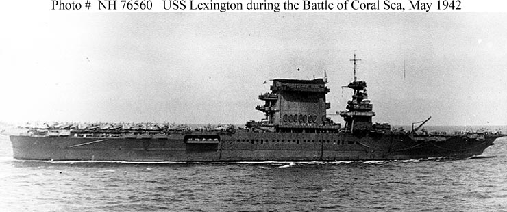
Curious about an object on page 57 of the new Lex book by Steve Wiper. Just behind the after most 1.1 mount in the pic there is a man that has abandoned ship by going down a rope and he has just landed on some type of something. What is that? Looks like a giant tomato. One other thing, was everyone aware that there were still life rafts hung on the port/inboard side of the funnel at Coral Sea. Look on page 44 in the upper left corner of the pic. And if you look at the top pic on page 63, you can see where the rafts hung due to the fact that when they took them down the previous coat of 5-O paint is exposed. They really were in a hurry to get that ship back in the fight. Sorry if this is old news but it's new to me. Jon
-
Dick J
- Posts: 1991
- Joined: Mon Aug 06, 2007 6:29 pm
Re: Calling all USS Lexington CV-2 fans
There was a photo posted on an Australian site about 3 years ago that showed Lex steaming just before the Coral Sea battle. It was a bit blurry, but the rafts on the inboard side were readily identifiable. It also showed that boats were still in the second and fourth boat pockets for the battle. Unfortunately, I only saved the link (which no longer works) instead of the photo itself.  That photo had been referenced earlier in this thread, but the reference was deleted when the link died. As for the photo on page 44, that also had been previously mentioned, but it is worthwhile to remind people about it!
That photo had been referenced earlier in this thread, but the reference was deleted when the link died. As for the photo on page 44, that also had been previously mentioned, but it is worthwhile to remind people about it! -
MartinJQuinn
- Posts: 8561
- Joined: Tue Jan 11, 2005 1:40 pm
- Location: New Jersey
Re: Calling all USS Lexington CV-2 fans
Fortunately, I saved the photo to my hard drive:
- Attachments
-
Martin
"Tomorrow is the most important thing in life. Comes into us at midnight very clean. It's perfect when it arrives and it puts itself in our hands. It hopes we've learned something from yesterday." John Wayne
Ship Model Gallery
"Tomorrow is the most important thing in life. Comes into us at midnight very clean. It's perfect when it arrives and it puts itself in our hands. It hopes we've learned something from yesterday." John Wayne
Ship Model Gallery
-
Dick J
- Posts: 1991
- Joined: Mon Aug 06, 2007 6:29 pm
Re: Calling all USS Lexington CV-2 fans
Martin, do you also have the "Meredith" photo from that batch?
With what we now know from Steve's new book, it is possible to make out some of the shape of the square-type FC radar above the former forward 8" control station. Even in this "fuzzy" photo!
With what we now know from Steve's new book, it is possible to make out some of the shape of the square-type FC radar above the former forward 8" control station. Even in this "fuzzy" photo!
-
Jerry Phillips
Re: Calling all USS Lexington CV-2 fans
Various raft notes........notice the large amount of 25 man (?) rafts stowed in the flight deck safety netting (8mm film footage..Jan'42). The port side funnel raft stacks (60/45man rafts stacked) were first installed early Dec. 1941. At first, only 5 stacks hung (Lundstrom's First Team, pg. 38), various Life mag photos, but by late Jan '42 the entire port funnel side was lined (9 stacks?).(Martin's photo above, Lundstrom's First Team pg.86, CW #33 pg.32-33). I also have the 8mm film (on DVD) mentioned above, and before the 20mm were installed in the port boat pockets, large no# of rafts were stowed there (circa Jan. '42), when the boats in those pockets, were removed.
Jerry Phillips
Jerry Phillips