Dave Wooley
1/100 Chaconia LPG carrier
Moderators: MartinJQuinn, JIM BAUMANN, HMAS, Tiny69, Dave Wooley
- Dave Wooley
- Posts: 4131
- Joined: Sat Jan 22, 2005 10:18 am
- Location: Liverpool
Re: 1/100 Chaconia LPG carrier
Hi Roel thanks for the clarification .
Dave Wooley

Dave Wooley
- Neptune
- Posts: 2466
- Joined: Sun Mar 13, 2005 11:51 am
- Location: Belgium
Re: 1/100 Chaconia LPG carrier
Finally the day is there. the hull is finished. Time for varnish (although it's probably too cold outside).
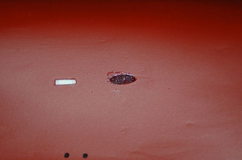
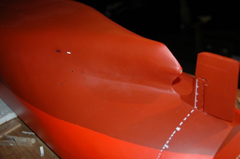
After the drafts I've painted the various seawater in-and outlets of the engine room black and placed grids in front of the seachests.
After some trying with PE railings, I decided to make it from a piece of curtain. It looks pretty cool although due to the close picture you generally see glue... I was/am a little scared that it won't hold in the water, but we'll see I guess. Also the varnish will help it glue to the hull I suppose. For now it's glued with two-component epoxy glue.
Perhaps some tidying up of the glue would be required. The thing you see painted white in front of the sea chest is part of the Impressed Current Corrosion Protection (ICCP) system. On these ships it looks like it was only used on the engine room part of the ship. In Flanders Harmony and all modern ships, it's placed along the whole hull.
By putting a small current on your plating (runs from this white thing to a small round anode further down the hull) you oppose the corrosion reaction (which creates by itself a current and since the hull is charged by you, it can't do that). These systems are always protected during drydocks and are only painted with special paint, therefore you see the white paint.
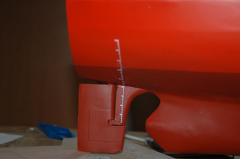
Final drafts.


Overview of the other side. Note the stretched draft numbering aft and the various overboards. So now it's up for varnishing and then I can finally start mounting the details on deck.

After the drafts I've painted the various seawater in-and outlets of the engine room black and placed grids in front of the seachests.
After some trying with PE railings, I decided to make it from a piece of curtain. It looks pretty cool although due to the close picture you generally see glue... I was/am a little scared that it won't hold in the water, but we'll see I guess. Also the varnish will help it glue to the hull I suppose. For now it's glued with two-component epoxy glue.
Perhaps some tidying up of the glue would be required. The thing you see painted white in front of the sea chest is part of the Impressed Current Corrosion Protection (ICCP) system. On these ships it looks like it was only used on the engine room part of the ship. In Flanders Harmony and all modern ships, it's placed along the whole hull.
By putting a small current on your plating (runs from this white thing to a small round anode further down the hull) you oppose the corrosion reaction (which creates by itself a current and since the hull is charged by you, it can't do that). These systems are always protected during drydocks and are only painted with special paint, therefore you see the white paint.
Final drafts.


Overview of the other side. Note the stretched draft numbering aft and the various overboards. So now it's up for varnishing and then I can finally start mounting the details on deck.

The merchant shipyard
-
Pieter
- Posts: 1608
- Joined: Sat Sep 17, 2005 9:19 am
Re: 1/100 Chaconia LPG carrier
Very nice and sharp work. About the ICCP, does this replace the traditional zinc blocks or zinc threads for corrosion protection?
- Neptune
- Posts: 2466
- Joined: Sun Mar 13, 2005 11:51 am
- Location: Belgium
Re: 1/100 Chaconia LPG carrier
Yes it does. In Chaconia and her sisters there are still anodes in the ballast tanks etc. since the ICCP is only used aft. The rudder has some anodes attached to it as well, since it's not well connected to the hull. On modern ships there are no anodes in the ballast tanks anymore, only ICCP. Anodes are nowadays mainly used in seawater inlets, pumps etc.
The merchant shipyard
- Neptune
- Posts: 2466
- Joined: Sun Mar 13, 2005 11:51 am
- Location: Belgium
Re: 1/100 Chaconia LPG carrier
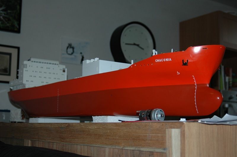
The weekend pictures. varnished, but with a small spot where it peeled off again. I had sprayed a little too much, so it formed drops. I wiped them off slowly, but after drying there was still some mark of a drop. I tried to cut it off, but a wider spot came loose. I guess I'll just respray the bow one more time. For the rest it looks ok. I'll do perhaps some weathering with oil paints afterwards, but I'll see that at the end of the build. I've dry fitted some of the details now. Lots of stuff as you can already see. And still the piping and supports are missing.
I'm currently working on the forward facing of the forepeak. There is a paint store and oil spill locker on Port and starboard side inside the forepeak. I'll first have to put some ballast tank and hold space entry hatches as well as the forward liferaft in place before I fix that.


I'm currently working on the forward facing of the forepeak. There is a paint store and oil spill locker on Port and starboard side inside the forepeak. I'll first have to put some ballast tank and hold space entry hatches as well as the forward liferaft in place before I fix that.


The merchant shipyard
- Neptune
- Posts: 2466
- Joined: Sun Mar 13, 2005 11:51 am
- Location: Belgium
Re: 1/100 Chaconia LPG carrier
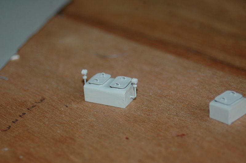
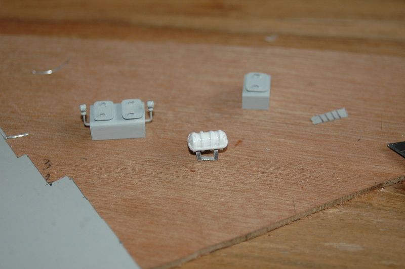
So, slowly continuing on the detailing of the forward area. Here you see the double bottom ballast tank entry hatch. Connected to a small venthead on each side. The single hatch for the hold space is also visible in the picture. Both of these items are placed below the forward deck in the open space. Furthermore you can also see a liferaft, with the first effort for a cradle (failed as you can see). This liferaft is also placed below that forward deck.
All of these items were placed in their place, and now I'm gluing the "facing" of that area in place. The doors and fireboxes for that space are also ready. Currently working on the windlass wheels.


All of these items were placed in their place, and now I'm gluing the "facing" of that area in place. The doors and fireboxes for that space are also ready. Currently working on the windlass wheels.


The merchant shipyard
- Capit�o Norbert
- Posts: 1993
- Joined: Tue Apr 17, 2007 9:18 am
- Location: Brasil
Re: 1/100 Chaconia LPG carrier
Hi Roel the hatches are very well made
i like

i like
- Paul Salomone
- Posts: 94
- Joined: Fri Feb 24, 2012 7:51 am
- Location: Malta
Re: 1/100 Chaconia LPG carrier
Hello Neptune,
Great work and neat finsh as well.
The detailing is getting on well as well.
WELL DONE.
Cheers.
Paul.
Great work and neat finsh as well.
The detailing is getting on well as well.
WELL DONE.
Cheers.
Paul.
NEVER RETREAT - NEVER SURRENDER
JUST DO IT YOUR WAY AND NEVER LOOK BACK
- Neptune
- Posts: 2466
- Joined: Sun Mar 13, 2005 11:51 am
- Location: Belgium
Re: 1/100 Chaconia LPG carrier
Thanks for the comments guys.
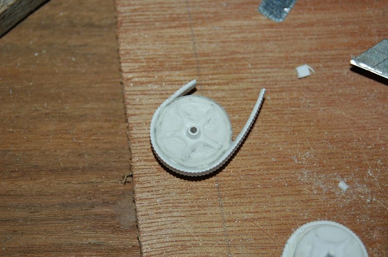
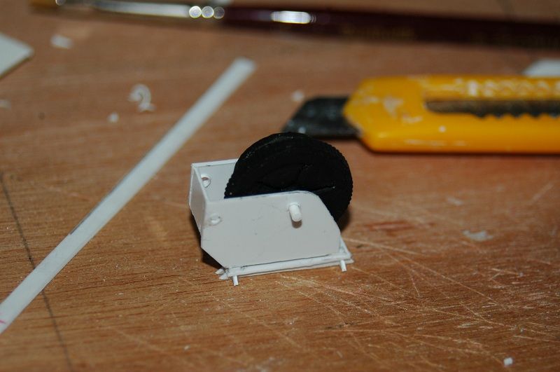
I'm in a sort of a builder's block, but I'm slowly crawling out of it. I'm working on the forward windlasses and got stuck on the gypsy wheels, the windlass part that lifts the anchor chain. It's a cog wheel, but partly covered for safety by a plate. I had different ideas of how to add cogs on the wheels. They were carved out in the centre to create a realistic shape. First I tried to cut the cogs by hand. That was driving me nuts and the result wasn't really great.
Afterwards I used a 1/700 trick, removing some threads from a piece of rough cloth, so that I kept a bunch of parallel threads with a decent diameter. These I glued around the wheel, since they were parallel and with regular spaces between they resembled cogs. I impregnated it with CA, so I could cut them afterwards.
The result was still not satisfactory.
Eventually I used an idea which I had from the beginning, using Evergreen clapboard. I only have the "shaw" shape of evergreen at home, so that wouldn't work properly. I went to the modelshop, since I needed some RC gear for the ship as well and bought some "steel plating" board with wedges. This I cut in a long strip and glued around the wheel. Result was finally satisfactory
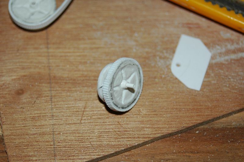
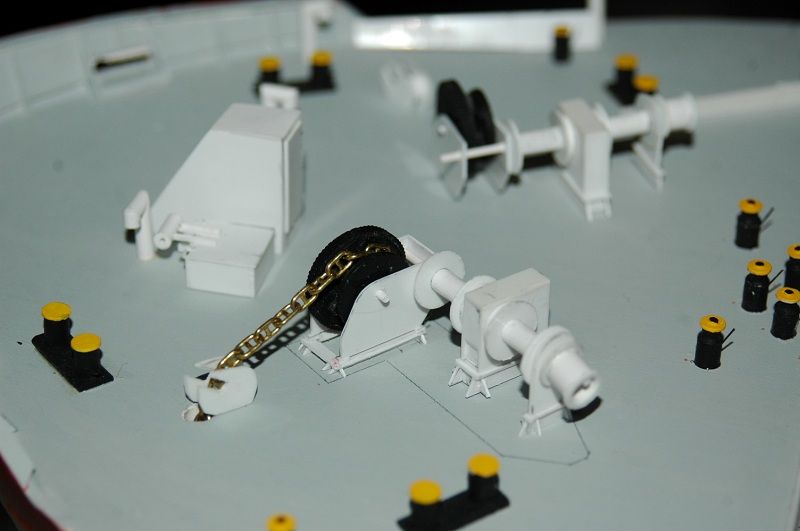
Here are finally those wheels. I also continued now with the base and line-up of the whole anchoring system. The lines on deck were the estimated drip tray outline. I'll have to increase it's size slightly, but not too much.


As mentioned, the protective cover still has to be added for most of the circumference of the wheel.


I'm in a sort of a builder's block, but I'm slowly crawling out of it. I'm working on the forward windlasses and got stuck on the gypsy wheels, the windlass part that lifts the anchor chain. It's a cog wheel, but partly covered for safety by a plate. I had different ideas of how to add cogs on the wheels. They were carved out in the centre to create a realistic shape. First I tried to cut the cogs by hand. That was driving me nuts and the result wasn't really great.
Afterwards I used a 1/700 trick, removing some threads from a piece of rough cloth, so that I kept a bunch of parallel threads with a decent diameter. These I glued around the wheel, since they were parallel and with regular spaces between they resembled cogs. I impregnated it with CA, so I could cut them afterwards.
The result was still not satisfactory.
Eventually I used an idea which I had from the beginning, using Evergreen clapboard. I only have the "shaw" shape of evergreen at home, so that wouldn't work properly. I went to the modelshop, since I needed some RC gear for the ship as well and bought some "steel plating" board with wedges. This I cut in a long strip and glued around the wheel. Result was finally satisfactory
Here are finally those wheels. I also continued now with the base and line-up of the whole anchoring system. The lines on deck were the estimated drip tray outline. I'll have to increase it's size slightly, but not too much.


As mentioned, the protective cover still has to be added for most of the circumference of the wheel.


The merchant shipyard
-
Pieter
- Posts: 1608
- Joined: Sat Sep 17, 2005 9:19 am
Re: 1/100 Chaconia LPG carrier
Very nice work Roel. What are those yellow-orange topped structures at he right of the picture?
- Capit�o Norbert
- Posts: 1993
- Joined: Tue Apr 17, 2007 9:18 am
- Location: Brasil
Re: 1/100 Chaconia LPG carrier
very nice 
- Dave Wooley
- Posts: 4131
- Joined: Sat Jan 22, 2005 10:18 am
- Location: Liverpool
Re: 1/100 Chaconia LPG carrier
Hi Roel I really like the way you have built up your Windlass, a good bit of lateral thinking there
Dave Wooley
Dave Wooley
- Paul Salomone
- Posts: 94
- Joined: Fri Feb 24, 2012 7:51 am
- Location: Malta
Re: 1/100 Chaconia LPG carrier
Hello Neptune,
Very nice work indeed. The construction is excellent with neat finish.
The detailing, especially the lugs at the bottom, really enhanced it's appearance.
Cheers.
Paul.
Very nice work indeed. The construction is excellent with neat finish.
The detailing, especially the lugs at the bottom, really enhanced it's appearance.
Cheers.
Paul.
NEVER RETREAT - NEVER SURRENDER
JUST DO IT YOUR WAY AND NEVER LOOK BACK
- Neptune
- Posts: 2466
- Joined: Sun Mar 13, 2005 11:51 am
- Location: Belgium
Re: 1/100 Chaconia LPG carrier
Thanks for the comments guys!
Hello Pieter,
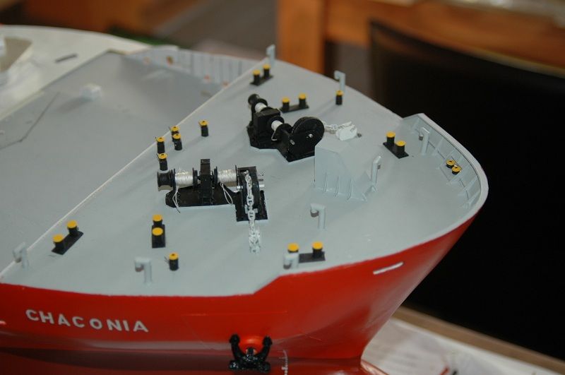
the yellow topped structures are called horizontal rollers (sometimes called "old man"). They are there to change the direction of a mooring rope without damaging it. The yellow topped thing has a rolling top, the small stanchion you see sticking out is there to keep the rope up (otherwise it falls off when the tension is gone). Like this the rope doesn't chafe and get damaged. There is a whole forrest of them forward as the ropes from both winch warping heads are used on both sides along with the ropes on the drums. A typical mooring is 3-3-2, which means 3 head lines, 3 breast lines and 2 spring lines. That means 6 lines have to be given from the forecastle and there are only 4 of them on a drum. That means 2 ropes are given and tensioned by the warping ends of these winches and put on bollards. It also means that 2 lines from the starboard or port winch drums have to be given all the way to the other side.
These rollers require some maintenance but they are pretty handy.
I'm close to finishing these windlass/winch arrangments now. I'm painting the anchor chain white since that's normal practice when it's "new". The first shackle (measure of length, approx 27m) of the chain is fully painted white, afterwards only the shackles (object) in front and after the kenter shackle (where two shackles (length measure) of chain are connected to each other) are painted white. So when two shackles of chain along with the anchor are overboard, you'll see two white painted shackles, the kenter shackle followed by 2 more white painted shackles on deck.
Since my anchors will be in position, you'll just see a white painted chain on deck (it gives some colour as well).
On one side I do intend to let some rust come through, same with some traces along the hull, of using that anchor just after a dry docking period. Often the white paint on the chain disappears after using it a few times and rust comes through.
Hello Pieter,
the yellow topped structures are called horizontal rollers (sometimes called "old man"). They are there to change the direction of a mooring rope without damaging it. The yellow topped thing has a rolling top, the small stanchion you see sticking out is there to keep the rope up (otherwise it falls off when the tension is gone). Like this the rope doesn't chafe and get damaged. There is a whole forrest of them forward as the ropes from both winch warping heads are used on both sides along with the ropes on the drums. A typical mooring is 3-3-2, which means 3 head lines, 3 breast lines and 2 spring lines. That means 6 lines have to be given from the forecastle and there are only 4 of them on a drum. That means 2 ropes are given and tensioned by the warping ends of these winches and put on bollards. It also means that 2 lines from the starboard or port winch drums have to be given all the way to the other side.
These rollers require some maintenance but they are pretty handy.
I'm close to finishing these windlass/winch arrangments now. I'm painting the anchor chain white since that's normal practice when it's "new". The first shackle (measure of length, approx 27m) of the chain is fully painted white, afterwards only the shackles (object) in front and after the kenter shackle (where two shackles (length measure) of chain are connected to each other) are painted white. So when two shackles of chain along with the anchor are overboard, you'll see two white painted shackles, the kenter shackle followed by 2 more white painted shackles on deck.
Since my anchors will be in position, you'll just see a white painted chain on deck (it gives some colour as well).
On one side I do intend to let some rust come through, same with some traces along the hull, of using that anchor just after a dry docking period. Often the white paint on the chain disappears after using it a few times and rust comes through.
The merchant shipyard
- Neptune
- Posts: 2466
- Joined: Sun Mar 13, 2005 11:51 am
- Location: Belgium
Re: 1/100 Chaconia LPG carrier
Another small update on the windlasses.
I didn't make any chain lockers before, so I had to drill the holes below the winches after fitting. The way I did it.
- drill a slightly larger hole like for the hawse pipe
- make a small pipe of required (and possible inside the hull) pipe, which you close at the bottom. So that you don't have any ingress of water in the hull
- make a small hole a the bottom, so that you can fit a small pin to lock the chain in place
- measure approximate length of chain needed to come from your pin connection inside the tube over the gypsy wheel to the anchor inside the hawse pipe
- cut chain to length and attach to the anchor
- go through the gypsy wheel support and place the tube below the normal winch place
- dry fit the assembly with the gypsy wheel (keep shaft removable) to see the correct length of chain
- adjust length by cutting the chain (if too long), or pulling the pipe up a little and cut off the excess piece of pipe above the deck (if chain is too short)
Here you can see the piece of styrene pipe, closed on the bottom and you can also see the bent pin, which I made of stainless steel wire (stronger than brass, so I can pull out the pipe as required)
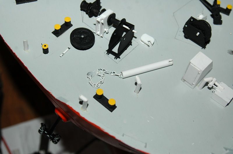
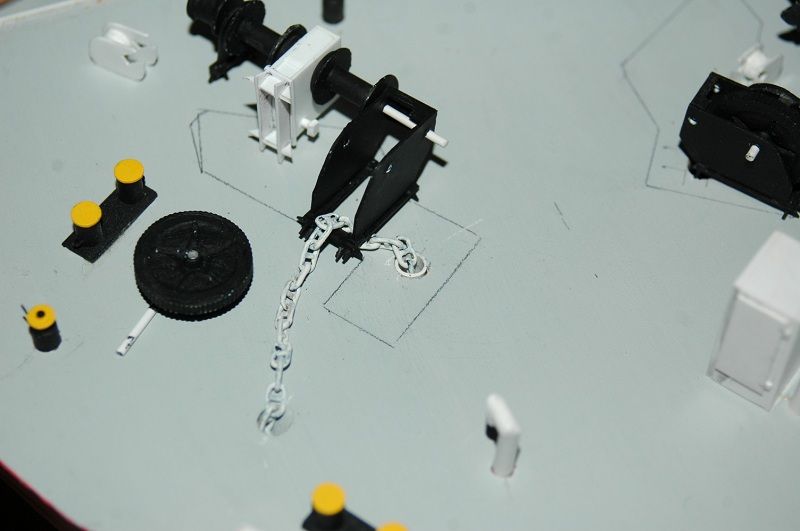
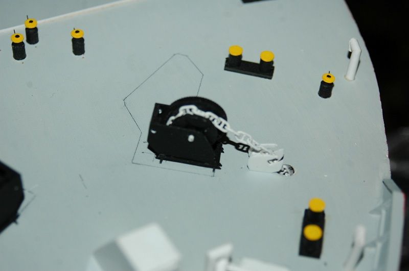
A more or less final fit. The driptray is already fitted, glued in small cuts in the deck. The entire inside will be painted black along with the remaining winch parts. Additional detailing will be done once the windlass is fully in place.
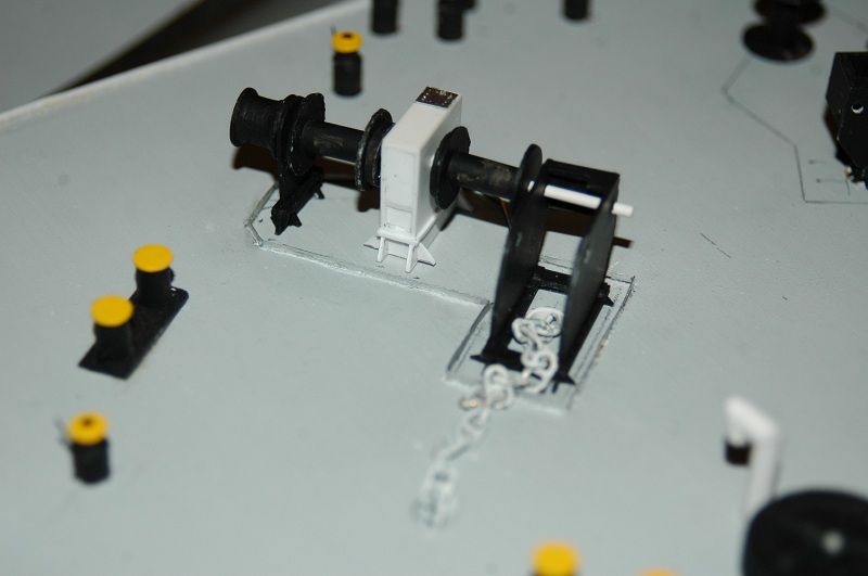
I didn't make any chain lockers before, so I had to drill the holes below the winches after fitting. The way I did it.
- drill a slightly larger hole like for the hawse pipe
- make a small pipe of required (and possible inside the hull) pipe, which you close at the bottom. So that you don't have any ingress of water in the hull
- make a small hole a the bottom, so that you can fit a small pin to lock the chain in place
- measure approximate length of chain needed to come from your pin connection inside the tube over the gypsy wheel to the anchor inside the hawse pipe
- cut chain to length and attach to the anchor
- go through the gypsy wheel support and place the tube below the normal winch place
- dry fit the assembly with the gypsy wheel (keep shaft removable) to see the correct length of chain
- adjust length by cutting the chain (if too long), or pulling the pipe up a little and cut off the excess piece of pipe above the deck (if chain is too short)
Here you can see the piece of styrene pipe, closed on the bottom and you can also see the bent pin, which I made of stainless steel wire (stronger than brass, so I can pull out the pipe as required)


A more or less final fit. The driptray is already fitted, glued in small cuts in the deck. The entire inside will be painted black along with the remaining winch parts. Additional detailing will be done once the windlass is fully in place.

The merchant shipyard
- Neptune
- Posts: 2466
- Joined: Sun Mar 13, 2005 11:51 am
- Location: Belgium
Re: 1/100 Chaconia LPG carrier
Been a while. Somehow I have the feeling I'm updating less when I'm at home...
So the forepeak with windlasses and forward bosun store entry is finished. The entry has been detailed with litho framing.

I've finally gotten myself into working on the RC part. Hope to launch her somewhere next week for a test.
This is like an Engine Room 2nd floor
The servo for the rudder will be integrated in this (removable) platform, the remaining space will be used for the receiver, ESC and some other gear.

One big question remains though. I made frame for the motor, but of course it's not entirely lined up with the shaft. The motor would be standing on the bottom, with the keel completely removed in that case.
The frame will be standing on top of a sloped part of the keel, to align it better with the shaft and the double coupling. Here is a picture. Do you think this will work? Or should I eventually remove the keel completely in that spot and put the motor on the bottom to line up straight with the shaft?
I've test run the motor from its slanted position and it seemed to be running ok, but I'm not sure... (since my experience is pretty small and the Udaloy motors were definately wrongly lined up)

The longitudinal strength after removing the keel can be compensated by putting pieces between the frames on both sides of the motor if it is necessary.
Furthermore I've also made a magnetic arrangement to keep the superstructure in place using cupboard magnets with 6kg force. I'll see if it stays
So the forepeak with windlasses and forward bosun store entry is finished. The entry has been detailed with litho framing.

I've finally gotten myself into working on the RC part. Hope to launch her somewhere next week for a test.
This is like an Engine Room 2nd floor

One big question remains though. I made frame for the motor, but of course it's not entirely lined up with the shaft. The motor would be standing on the bottom, with the keel completely removed in that case.
The frame will be standing on top of a sloped part of the keel, to align it better with the shaft and the double coupling. Here is a picture. Do you think this will work? Or should I eventually remove the keel completely in that spot and put the motor on the bottom to line up straight with the shaft?
I've test run the motor from its slanted position and it seemed to be running ok, but I'm not sure... (since my experience is pretty small and the Udaloy motors were definately wrongly lined up)

The longitudinal strength after removing the keel can be compensated by putting pieces between the frames on both sides of the motor if it is necessary.
Furthermore I've also made a magnetic arrangement to keep the superstructure in place using cupboard magnets with 6kg force. I'll see if it stays
The merchant shipyard
-
HvyCgn9
- Posts: 771
- Joined: Mon May 10, 2010 9:09 am
- Location: Adelaide,SouthOZ
Re: 1/100 Chaconia LPG carrier
With your motor alignment I would take it off the angled mount and just use RTV silicon (bathroom silicon!) to attach it to the wood blocks you already have in place, this should lower the motor and give you a much better line up with the shaft. I used a this method in my 1/72 Anchor handling tug with no dramas.
Cheers Bruce
PS: Thats a sweet LPG carrier!!

Cheers Bruce
PS: Thats a sweet LPG carrier!!
building:
1/72 RC USS LONG BEACH CGN9
1/72 RC USS CALIFORNIA CGN36
1/72 RC USS SAIPAN LHA2
1/72 RC USS JOHN PAUL JONES DDG53
1/72 RC USS SHARK SSN591
1/72 RC USS SEAWOLF SSN21
1/72 RC USS ALBANY CG10
1/72 RC USS LONG BEACH CGN9
1/72 RC USS CALIFORNIA CGN36
1/72 RC USS SAIPAN LHA2
1/72 RC USS JOHN PAUL JONES DDG53
1/72 RC USS SHARK SSN591
1/72 RC USS SEAWOLF SSN21
1/72 RC USS ALBANY CG10
- Dave Wooley
- Posts: 4131
- Joined: Sat Jan 22, 2005 10:18 am
- Location: Liverpool
Re: 1/100 Chaconia LPG carrier
Hi Roel very smart build indeed , I like the detail work on the forepeak and the one asset you really don't see on to many warships these days a smattering of colour. As for the shaft the method mentioned by Bruce for securing the motor does work but if you want to replace the motor it can be a messy job. If you have sufficient space after removing a section of the keelson to centre the shaft to the motor I would try to stay with the mounting. BUT if all else fails then go with what Bruce has suggested.
Dave Wooley

Dave Wooley
- DrPR
- Posts: 1689
- Joined: Sun Mar 07, 2010 12:01 am
- Location: Corvallis, Oregon, USA
- Contact:
Re: 1/100 Chaconia LPG carrier
Roel,
Another idea would be to rotate the motor 180 degrees around the long axis (as shown in the picture). This would place the "bottom" of the "L" mounting bracket above the motor, allowing you to lower the motor closer to in line with the shaft. You could even cut away a bit of the keel and frames to allow the motor to sit lower.
The "L" bracket would then be mounted on a transverse support between frames - a sturdy support of course.
Phil
Another idea would be to rotate the motor 180 degrees around the long axis (as shown in the picture). This would place the "bottom" of the "L" mounting bracket above the motor, allowing you to lower the motor closer to in line with the shaft. You could even cut away a bit of the keel and frames to allow the motor to sit lower.
The "L" bracket would then be mounted on a transverse support between frames - a sturdy support of course.
Phil
A collision at sea will ruin your entire day. Aristotle
- Neptune
- Posts: 2466
- Joined: Sun Mar 13, 2005 11:51 am
- Location: Belgium
Re: 1/100 Chaconia LPG carrier
Thanks for the suggestions guys.
Since all of you are looking for a way to lower that motor, I guess I'll stick with that. I'm drilling out part of the keel to lower the motor. She will remain at some angle though. I've been test running it with the shaft etc. connected and at certain angles it's much better than at other angles. If I can't get it horizontally lined up to the shaft, I should at least try to keep the angle on both connections under a minimal angle and in the same direction. If I put it horizontal, but higher than the shaft, the connections are at an opposing angle and it doesn't work well.
In general I want to keep it slightly higher than the bottom to avoid any damage by possible water ingress. I'll be trimming her on the stern in ballast condition, so that means any water ingress would go straight to the motor/shaft position. Better to have that motor sitting slightly up I guess. I will however lower it a little and keep the frame (in order to have it at about the same position as Bruce suggested with silicone).
Mounting it like Phil suggests would be fairly ok too, but having enough strength in that position will be difficult, the frames are fairly wide there and having it under a correct angle would require some engineering as well. (along with cutting the top of the L frame.
Since all of you are looking for a way to lower that motor, I guess I'll stick with that. I'm drilling out part of the keel to lower the motor. She will remain at some angle though. I've been test running it with the shaft etc. connected and at certain angles it's much better than at other angles. If I can't get it horizontally lined up to the shaft, I should at least try to keep the angle on both connections under a minimal angle and in the same direction. If I put it horizontal, but higher than the shaft, the connections are at an opposing angle and it doesn't work well.
In general I want to keep it slightly higher than the bottom to avoid any damage by possible water ingress. I'll be trimming her on the stern in ballast condition, so that means any water ingress would go straight to the motor/shaft position. Better to have that motor sitting slightly up I guess. I will however lower it a little and keep the frame (in order to have it at about the same position as Bruce suggested with silicone).
Mounting it like Phil suggests would be fairly ok too, but having enough strength in that position will be difficult, the frames are fairly wide there and having it under a correct angle would require some engineering as well. (along with cutting the top of the L frame.
The merchant shipyard