Very possibly. I have hung out with Cliffy in person, and he's a stud. He can't keep off the snatch offered to him. He is like a candle to the moth.Fliger747 wrote:Perhaps Cliffy was distracted by a young lady attractively garbed?
Cheers: T
Calling all Iowa-class (BB-61) fans
Moderators: BB62vet, MartinJQuinn, Timmy C, Gernot, Olaf Held, Dan K, HMAS, ModelMonkey
- navydavesof
- Posts: 3127
- Joined: Thu Mar 05, 2009 10:38 pm
Re: Calling all USS Iowa class fans
Proper Preparation Prevents Poor Performance
- Cliffy B
- Posts: 3125
- Joined: Sun Feb 01, 2009 3:55 pm
- Location: Hawaii
- Contact:
Re: Calling all USS Iowa class fans
Oh good grief.... No comment, no comment, and no comment
We're actually in the process of overhauling all the main deck hatches from Turret 3 aft. Needle guns!!!
Is it wrong that I find needle guns a stress reliever?
I'll post some photos of them later and try to remember to take some new shots of the main deck aft for the one who asked for them a while back; SORRY for the delay!
We're actually in the process of overhauling all the main deck hatches from Turret 3 aft. Needle guns!!!
Is it wrong that I find needle guns a stress reliever?
I'll post some photos of them later and try to remember to take some new shots of the main deck aft for the one who asked for them a while back; SORRY for the delay!
Drawing Board:
1/700 Whiff USS Leyte and escorts 1984
1/700 Whiff USN Modernized CAs 1984
1/700 Whiff ASW Showdown - FFs vs SSGN 1984
Slipway:
1/700 Whiff USN ASW Hunter Killer Group Dio 1984
1/700 Whiff USS Leyte and escorts 1984
1/700 Whiff USN Modernized CAs 1984
1/700 Whiff ASW Showdown - FFs vs SSGN 1984
Slipway:
1/700 Whiff USN ASW Hunter Killer Group Dio 1984
-
RandyM
- Posts: 337
- Joined: Sat Dec 15, 2007 10:40 pm
- Location: San Diego
Re: Calling all USS Iowa class fans
More questions about stuff...
First, for anyone who may be wondering, I have not had an opportunity to do any more work on the hull correction since the last round of photos. Pesky work keeps getting in the way and I'm one of those types who refuses to work on something if I can't get my head into it.
Having said that, I *have* been working on the 3D model. I got the 5-inch turrets roughed in, and have been looking at the 03-deck overhead supports. If anyone has any photos of this area - specifically around the breezeway - I would dearly love to see them.
Next, I have started adding bulkhead detail - the photo below shows the only section I've been working on, which is the very forward maindeck house on the stbd side. What are the objects that appear all over the ship, at the lower arrow in this image? I can guess deck lights, air vents, etc. but don't *know.* Plus, there seems to be numerous styles. Some have an offset away from the house at the bottom, others are straight. Then they differ in diameter, etc. Can someone help?
Finally, what is the section at the forward end of the 02 deck where it meets the conning tower (upper arrow in image). It appears to be a simple bulwark floating in space. ????
Thanks...


First, for anyone who may be wondering, I have not had an opportunity to do any more work on the hull correction since the last round of photos. Pesky work keeps getting in the way and I'm one of those types who refuses to work on something if I can't get my head into it.
Having said that, I *have* been working on the 3D model. I got the 5-inch turrets roughed in, and have been looking at the 03-deck overhead supports. If anyone has any photos of this area - specifically around the breezeway - I would dearly love to see them.
Next, I have started adding bulkhead detail - the photo below shows the only section I've been working on, which is the very forward maindeck house on the stbd side. What are the objects that appear all over the ship, at the lower arrow in this image? I can guess deck lights, air vents, etc. but don't *know.* Plus, there seems to be numerous styles. Some have an offset away from the house at the bottom, others are straight. Then they differ in diameter, etc. Can someone help?
Finally, what is the section at the forward end of the 02 deck where it meets the conning tower (upper arrow in image). It appears to be a simple bulwark floating in space. ????
Thanks...

- James M
- Posts: 252
- Joined: Fri Apr 01, 2005 11:30 pm
- Location: Fullerton, CA
Re: Calling all USS Iowa class fans
It's a metal shield covering the vent plenum. It's open at the top and the bottom.
Here's a picture of the vent:
http://navsource.org/archives/01/061/016173b.jpg
Here's a picture of the vent:
http://navsource.org/archives/01/061/016173b.jpg
-
Fliger747
- Posts: 5068
- Joined: Wed Jan 02, 2013 1:15 am
Re: Calling all USS Iowa class fans
Those are covers for vents, however on the current BB63 they are plated over ( I have peeked). I do hav'e some photos of the bridge wing supports posted in some earlier page. Whether or not these have changed I have no idea. On BB63 the forward stanchion stb side has been cut short.
Cheers. Tom
Cheers. Tom
Last edited by Fliger747 on Mon Sep 01, 2014 12:58 am, edited 1 time in total.
-
Fliger747
- Posts: 5068
- Joined: Wed Jan 02, 2013 1:15 am
Re: Calling all USS Iowa class fans
The log hooked units (3) on the bulkhead are for fire fighting, they are extensions to make a water "fog" for some types of flame suppression. A WAG on the risers, they may be for pressure equalization of otherwise water and air tight compartments below decks.
T
T
- BB62vet
- Posts: 3151
- Joined: Mon Nov 18, 2013 3:41 pm
- Location: Mocksville, NC
Re: Calling all USS Iowa class fans
RandyM -
Your upper arrow points to what appears to be (as Tom F. mentioned) a vent plenum cover, in this case an extension of the bulkhead extending from the 01 Level up to the 03 Navigational Bridge level - I think that this photo (http://www.navsource.org/archives/01/016339c.jpg) better illustrates this than the one provided by James M. - in fact, I'm not so sure that the photo he shows is of MISSOURI since she was built with the square bridge from the start.
Your lower arrow points to possibly a sanitary pipe vent coming from perhaps a lower deck head (?).
Hope this helps,
Hank
Your upper arrow points to what appears to be (as Tom F. mentioned) a vent plenum cover, in this case an extension of the bulkhead extending from the 01 Level up to the 03 Navigational Bridge level - I think that this photo (http://www.navsource.org/archives/01/016339c.jpg) better illustrates this than the one provided by James M. - in fact, I'm not so sure that the photo he shows is of MISSOURI since she was built with the square bridge from the start.
Your lower arrow points to possibly a sanitary pipe vent coming from perhaps a lower deck head (?).
Hope this helps,
Hank
HMS III
Mocksville, NC
BB62 vet 68-69
Builder's yard:
USS STODDARD (DD-566) 66-68 1:144, Various Lg Scale FC Directors
Finished:
USS NEW JERSEY (BB-62) 67-69 1:200
USN Sloop/Ship PEACOCK (1813) 1:48
ROYAL CAROLINE (1748) 1:47
AVS (1768) 1:48
Mocksville, NC
BB62 vet 68-69
Builder's yard:
USS STODDARD (DD-566) 66-68 1:144, Various Lg Scale FC Directors
Finished:
USS NEW JERSEY (BB-62) 67-69 1:200
USN Sloop/Ship PEACOCK (1813) 1:48
ROYAL CAROLINE (1748) 1:47
AVS (1768) 1:48
-
RandyM
- Posts: 337
- Joined: Sat Dec 15, 2007 10:40 pm
- Location: San Diego
Re: Calling all USS Iowa class fans
Thanks all - I spent some time poring over the FDD plans and found what I think is the definition used for these pipes - "Air Escape." Which sounds like maybe a pressure equalization vent? They are listed in (at least) three different diameters.
-
Fliger747
- Posts: 5068
- Joined: Wed Jan 02, 2013 1:15 am
Re: Calling all USS Iowa class fans
Randy!
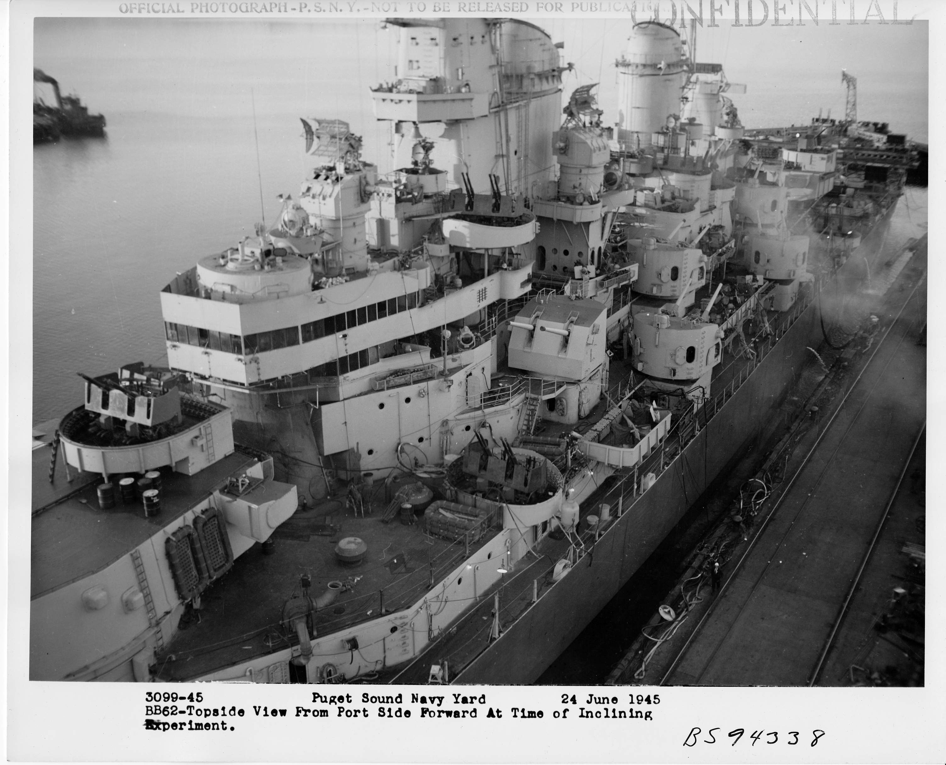
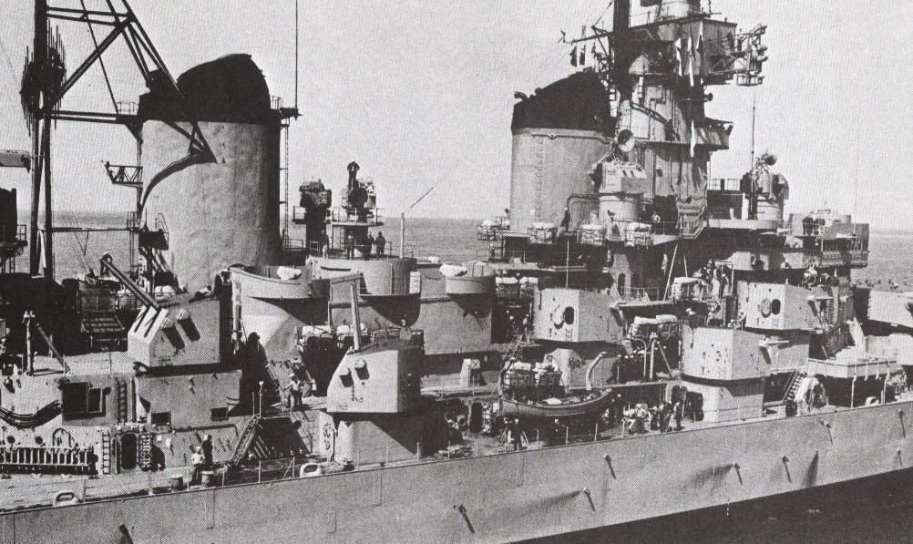
Very nice progression. I do see one possible error. In font of the fwd stbd 5" mount there is a platform to which an inclined ladder is attached (eventually) to the 02 level. The platform should be at the same level as the base of the mount behind, the deck is not elevated above the base of the mount as it is on the kit, instead there is a verticle lip to the scupper on the 02 deck which from the side in photos makes the deck look higher than it actually is. To reiterate the 02 deck level is at the level of the deck around the base of the 5" mounts, which do not have a lip. The kit screwed this up. I have photos which I can share if there is confusion.
Cheers. Tom
Very nice progression. I do see one possible error. In font of the fwd stbd 5" mount there is a platform to which an inclined ladder is attached (eventually) to the 02 level. The platform should be at the same level as the base of the mount behind, the deck is not elevated above the base of the mount as it is on the kit, instead there is a verticle lip to the scupper on the 02 deck which from the side in photos makes the deck look higher than it actually is. To reiterate the 02 deck level is at the level of the deck around the base of the 5" mounts, which do not have a lip. The kit screwed this up. I have photos which I can share if there is confusion.
Cheers. Tom
-
RandyM
- Posts: 337
- Joined: Sat Dec 15, 2007 10:40 pm
- Location: San Diego
Re: Calling all USS Iowa class fans
As I understand it, you are describing the area circled in red below. I'm glad you brought this up because it is a curiosity to me: I've been working from FDD drawings and photos (haven't even really looked at kit superstructure parts yet), and the drawings seem to indicate that the turret mounts (I guess they are actually the "barbettes" or ammo rooms for the 5" gun above) are somewhat lower than the deck level, while the photos I've found are somewhat inconclusive.
Given your description it sounds that the top of the mount is co-planar with the steel deck, and the apparent mis-match is likely due to the lip you describe along with the teak overlay in the vicinity.
Thank you as always. Can you tell me - is this true of all five-inch mounts?
Any photos you have are always hugely appreciated. Especially the non-touristy boring ones showing construction/architectural details. I think I've finally made my mind up to build a 1/96 Iowa-class when I'm done with this current effort, so this 3D model will hopefully become my primary reference.
Randy

Given your description it sounds that the top of the mount is co-planar with the steel deck, and the apparent mis-match is likely due to the lip you describe along with the teak overlay in the vicinity.
Thank you as always. Can you tell me - is this true of all five-inch mounts?
Any photos you have are always hugely appreciated. Especially the non-touristy boring ones showing construction/architectural details. I think I've finally made my mind up to build a 1/96 Iowa-class when I'm done with this current effort, so this 3D model will hopefully become my primary reference.
Randy

-
Fliger747
- Posts: 5068
- Joined: Wed Jan 02, 2013 1:15 am
Re: Calling all USS Iowa class fans
Port side, 52 and 54 mount bases. The vertical plate along the deck edge is about 8" wide and protrudes about equally above and below the actual deck level. The finished deck level around the mount is steel and is at the same level as the surface of the teak.
Tom
Tom
- BB62vet
- Posts: 3151
- Joined: Mon Nov 18, 2013 3:41 pm
- Location: Mocksville, NC
Re: Calling all USS Iowa class fans
Randy,
Tom is correct - the teak deck is at the same level as the 5" gun mount's metal deck onto which the mount's training rings and associated equipment are located. The space below the mount is called the Upper Handling Room and it has loading equipment to service the dual 5" guns in the mount. All 5" gun mounts are arranged the same - starting at the top of the system and going down - 5" gun mount, Upper Handling Room, Lower Handling Room, 5" projectile and powder hoists (either above or below), and their associated magazines. My berthing area on NJ was on the 01 level and we had two 5" hoists diagonally located in our berthing area. These went to Mount 55, located above our berthing area on the 02 Level - its lower handling room was below us with the hoists connecting the upper/lower handling rooms with berthing between. The steel deck that surrounds the mount rings only has a low lip at the outer edge that extends above the surface of the metal plate. Here is a shot from Navsource (http://navsource.org/archives/01/062/016293.jpg) that shows the port 5" mounts on NEW JERSEY - the deck is at the same elevation as the upper handling room overhead (ceiling); the lip of metal at the edge is indiscernible, but it's there. Perhaps Tom has a better shot of a 5" gun mount's base and adjoining deck plating.
One other item, just as a matter of clarification - 5" gun MOUNTS, 16" gun TURRETS. Likewise, 6"-47 cal. gun TURRETS (Light Cruiser main battery), 8"-55 cal gun TURRETS (Heavy Cruiser main battery). 5" and below in size are called mounts, 6" and above are turrets.
Your 3D rendering is really coming together!
Hank
Tom is correct - the teak deck is at the same level as the 5" gun mount's metal deck onto which the mount's training rings and associated equipment are located. The space below the mount is called the Upper Handling Room and it has loading equipment to service the dual 5" guns in the mount. All 5" gun mounts are arranged the same - starting at the top of the system and going down - 5" gun mount, Upper Handling Room, Lower Handling Room, 5" projectile and powder hoists (either above or below), and their associated magazines. My berthing area on NJ was on the 01 level and we had two 5" hoists diagonally located in our berthing area. These went to Mount 55, located above our berthing area on the 02 Level - its lower handling room was below us with the hoists connecting the upper/lower handling rooms with berthing between. The steel deck that surrounds the mount rings only has a low lip at the outer edge that extends above the surface of the metal plate. Here is a shot from Navsource (http://navsource.org/archives/01/062/016293.jpg) that shows the port 5" mounts on NEW JERSEY - the deck is at the same elevation as the upper handling room overhead (ceiling); the lip of metal at the edge is indiscernible, but it's there. Perhaps Tom has a better shot of a 5" gun mount's base and adjoining deck plating.
One other item, just as a matter of clarification - 5" gun MOUNTS, 16" gun TURRETS. Likewise, 6"-47 cal. gun TURRETS (Light Cruiser main battery), 8"-55 cal gun TURRETS (Heavy Cruiser main battery). 5" and below in size are called mounts, 6" and above are turrets.
Your 3D rendering is really coming together!
Hank
Last edited by BB62vet on Tue Sep 02, 2014 8:22 pm, edited 1 time in total.
HMS III
Mocksville, NC
BB62 vet 68-69
Builder's yard:
USS STODDARD (DD-566) 66-68 1:144, Various Lg Scale FC Directors
Finished:
USS NEW JERSEY (BB-62) 67-69 1:200
USN Sloop/Ship PEACOCK (1813) 1:48
ROYAL CAROLINE (1748) 1:47
AVS (1768) 1:48
Mocksville, NC
BB62 vet 68-69
Builder's yard:
USS STODDARD (DD-566) 66-68 1:144, Various Lg Scale FC Directors
Finished:
USS NEW JERSEY (BB-62) 67-69 1:200
USN Sloop/Ship PEACOCK (1813) 1:48
ROYAL CAROLINE (1748) 1:47
AVS (1768) 1:48
-
Fliger747
- Posts: 5068
- Joined: Wed Jan 02, 2013 1:15 am
Re: Calling all USS Iowa class fans
53 Mount stbd side. Note the teak decking is level with the waterway at deck edge and same level as the mount base top.
-
Fliger747
- Posts: 5068
- Joined: Wed Jan 02, 2013 1:15 am
Re: Calling all USS Iowa class fans
Flag bridge port side. Note stanchions fwd. On the stbd side the most fwd stanchion has been cutoff at bulwark top. Note that the steel decking flush with the teak fwd was added during modernization for splinter protection to areas below. Originally planked...
Tom
Tom
-
RandyM
- Posts: 337
- Joined: Sat Dec 15, 2007 10:40 pm
- Location: San Diego
Re: Calling all USS Iowa class fans
Below is a quick render of that area on my 3D model. The lighting is all goofed up (sunlight coming from left, faux light source from right so you can see the overhead details). As you can see, I only have the aft portion of the overhead "built" because I don't have any good photos of this area.
I'm going to fix the 5-inch mounts tonight: thanks for all the help!
Randy

I'm going to fix the 5-inch mounts tonight: thanks for all the help!
Randy

-
RandyM
- Posts: 337
- Joined: Sat Dec 15, 2007 10:40 pm
- Location: San Diego
Re: Calling all USS Iowa class fans
Here's the corrected mounts at the 02-level. I also added the coaming per the photo you supplied: thank you. Ignore those 40mm shells floating in space - they're an "experiment in process."
Please let me know if you see anything else (granted there are a lot of little issues to be dealt with). For example, I need to add the waterway on 02, but that's an n-th order detail for later.

Please let me know if you see anything else (granted there are a lot of little issues to be dealt with). For example, I need to add the waterway on 02, but that's an n-th order detail for later.

-
Fliger747
- Posts: 5068
- Joined: Wed Jan 02, 2013 1:15 am
Re: Calling all USS Iowa class fans
Stanchions:
Note there is one at the corner of the bulwark on the lower bulwark on the flag bridge that is not in line with the others. Also a window next to the hatchway leading into the enclosed area.
Cheers: T
Note there is one at the corner of the bulwark on the lower bulwark on the flag bridge that is not in line with the others. Also a window next to the hatchway leading into the enclosed area.
Cheers: T
- James M
- Posts: 252
- Joined: Fri Apr 01, 2005 11:30 pm
- Location: Fullerton, CA
Re: Calling all USS Iowa class fans
I'm not sure of the level of detail you are after with the 3D model but it looks like your after as much as you can find.
I really like the attention to detail you have put into this so far.
Here are a couple of very minor details:
The last 2 stanchions that support the 40mm mount are larger diameter than the others.
Also, the midships 40mm nest, the aft portion that tapered and radiused doesn't extend to the top of the structure. It stops about 30" below
Here is a picture of it:
http://www.navsource.org/archives/01/016296.jpg
Hope this is helpful and not critical
James
I really like the attention to detail you have put into this so far.
Here are a couple of very minor details:
The last 2 stanchions that support the 40mm mount are larger diameter than the others.
Also, the midships 40mm nest, the aft portion that tapered and radiused doesn't extend to the top of the structure. It stops about 30" below
Here is a picture of it:
http://www.navsource.org/archives/01/016296.jpg
Hope this is helpful and not critical
James
-
RandyM
- Posts: 337
- Joined: Sat Dec 15, 2007 10:40 pm
- Location: San Diego
Re: Calling all USS Iowa class fans
Tom:
I missed that stanchion - thanks. As for the after windows on the enclosed flag deck, I'm not sure of their dimensions. That whole section of the model needs work, specifically the header above the windows - right now the "glass" goes all the way to the top of the bulkhead. Also, the hatch as drawn is based on dimensions provided on the FDD plans, and it certainly looks anemic. Anyway, below is the revision based on your sharp eyes.
James:
In my line of work critical reviews are a hugely valuable tool... please criticize away - it is most welcome. My goal is to have as much detail as possible given the limits of my computer/time, and to be as accurate as possible given reasonably-available (and accurate!) research material. I'll definitely rework the 40mm triple tower. Do you happen to know the diameter of the larger stanchions?
Randy

I missed that stanchion - thanks. As for the after windows on the enclosed flag deck, I'm not sure of their dimensions. That whole section of the model needs work, specifically the header above the windows - right now the "glass" goes all the way to the top of the bulkhead. Also, the hatch as drawn is based on dimensions provided on the FDD plans, and it certainly looks anemic. Anyway, below is the revision based on your sharp eyes.
James:
In my line of work critical reviews are a hugely valuable tool... please criticize away - it is most welcome. My goal is to have as much detail as possible given the limits of my computer/time, and to be as accurate as possible given reasonably-available (and accurate!) research material. I'll definitely rework the 40mm triple tower. Do you happen to know the diameter of the larger stanchions?
Randy

-
RandyM
- Posts: 337
- Joined: Sat Dec 15, 2007 10:40 pm
- Location: San Diego
Re: Calling all USS Iowa class fans
Corrected 40mm triple tower - thanks again James. I eyeballed this from the photo you provided. I did take a quick look at the drawings I have and they don't show this detail well. If anyone has dimensions for this I'd appreciate it.