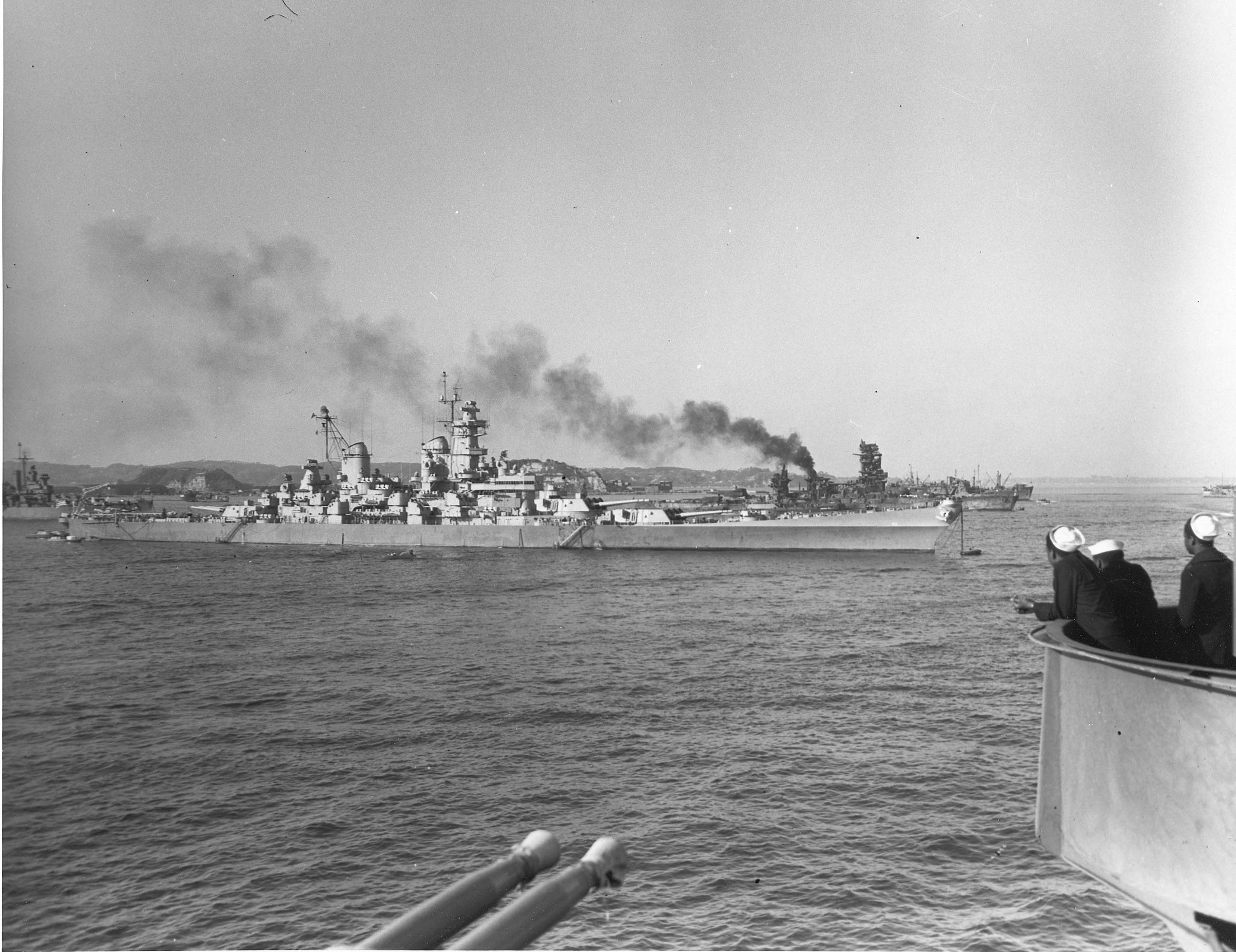
RandyM wrote:Jim... I would be very interested in obtaining a copy of said offsets. Are they for sale somewhere/anywhere?
The bad news: I don't have anything to sell. I manually copied them from blurry images and made corrections using Turbocad. Some of the values are impossible to read and plotting them allows you to tell if its really a 5 or a 6 or to get values that are totally unreadable. The data is in several Turbocad files with sets. I don't have anything packaged.
The good news: I could probably generate a specific data set for your needs if you can tell me what data you're looking for.
RandyM wrote:Jim... I would be very interested in obtaining a copy of said offsets. Are they for sale somewhere/anywhere?
The bad news: I don't have anything to sell. I manually copied them from blurry images and made corrections using Turbocad. Some of the values are impossible to read and plotting them allows you to tell if its really a 5 or a 6 or to get values that are totally unreadable. The data is in several Turbocad files with sets. I don't have anything packaged.
The good news: I could probably generate a specific data set for your needs if you can tell me what data you're looking for.
Are the originals or the blurry images publically available anywhere?
Assessing the impact of new area rug under modeling table.
I'm looking for every/anything that describes the aft third of the hull. My v.1 version of the "hull correction kit" is based on scanning the loft lines from plans, then setting the grid up in SolidWorks based on known measurements (ie., the plans include a grid which is centered on four-foot intervals, etc.). This yields a fairly accurate dataset - or at least, accurate-enough for my purposes. However, the final required step is that of tracing (in SW) the scanned lines into a sketch. Again, this yields excellent results, but as I found with the first printed parts, it's not quite "good enough" anymore. Specifically, the inboard edges of the tunnel should be very smooth and continuous, and what I wound up with - due to simple tracing errors - was not quite so perfect. I had to go in and correct the sketches manually, which was quite time consuming.
I've been looking at ways to reduce this sort of error for v.2, but the absolute best way (IMO) would be to work from original data tables. As I understand it, the state of the art in naval architecture in the 1930s was sort of the reverse of what it is today: draftsmen would "loft the hull" by drawing continuous lines, the offset tables were derived by measuring these lines, and refinements would be made in an iterative method, whereas today (again, per my understanding which could be faulty) hulls forms are generated by creating equation-driven offset tables first, and the lines are then taken from those data.
To get all the blurry images, you can order a CD from NARA asking for the Iowa Table of Offsets. I'd not recommend that as the quality is bad but you can do that.
Given that I have all this data scattered about my computer, how could I format the data so that it would be useful to you?
Some of the data is in X,Y,Z coordinates. Some is radii. Some is molded data. Some is plated. I have it loaded into Turbocad where I have interpolated lines and curves. If I just sent a bunch of files it would be pretty meaningless but I could clean up for you. I
There are some odd data points completely missing in the data. For example, the aft end of the tunnel is not well described by the data.
I found that I had created a spreadsheet that for someone else. I tried attaching here but xlxx files are not permitted.
My recollection of this area aboard Missouri is a rabbit warren of officers staterooms etc, with no external WT door in the port bulkhead. To make an equivalent area to the Captains suite would require removal of an enormous number of bulkheads and structure. I can just see the admirals wife coming aboard and with a wave to the yard commander, move all these "walls" (probably wanted to raise the "cieling" as well.
That's why I have a "Little house behind the House" - Big enough to hide in!!!
Hank
HMS III
Mocksville, NC
BB62 vet 68-69
Builder's yard:
USS STODDARD (DD-566) 66-68 1:144, Various Lg Scale FC Directors Finished:
USS NEW JERSEY (BB-62) 67-69 1:200
USN Sloop/Ship PEACOCK (1813) 1:48
ROYAL CAROLINE (1748) 1:47
AVS (1768) 1:48
A good friend has a large and quite nice house with an airstrip. Last year they did just that, move the bathroom across the hall and expand the kitchen into the bathroom area... Reading one of those kitchen remodel example books, several cost in the $200,000 range, and every time it involved moving the walls and often the ceiling as well! Afraid to ask him, probably more than it cost me to build my house.
I believe it was Everett Dirksen who said " a billion here and there and pretty soon you are talking real money!".
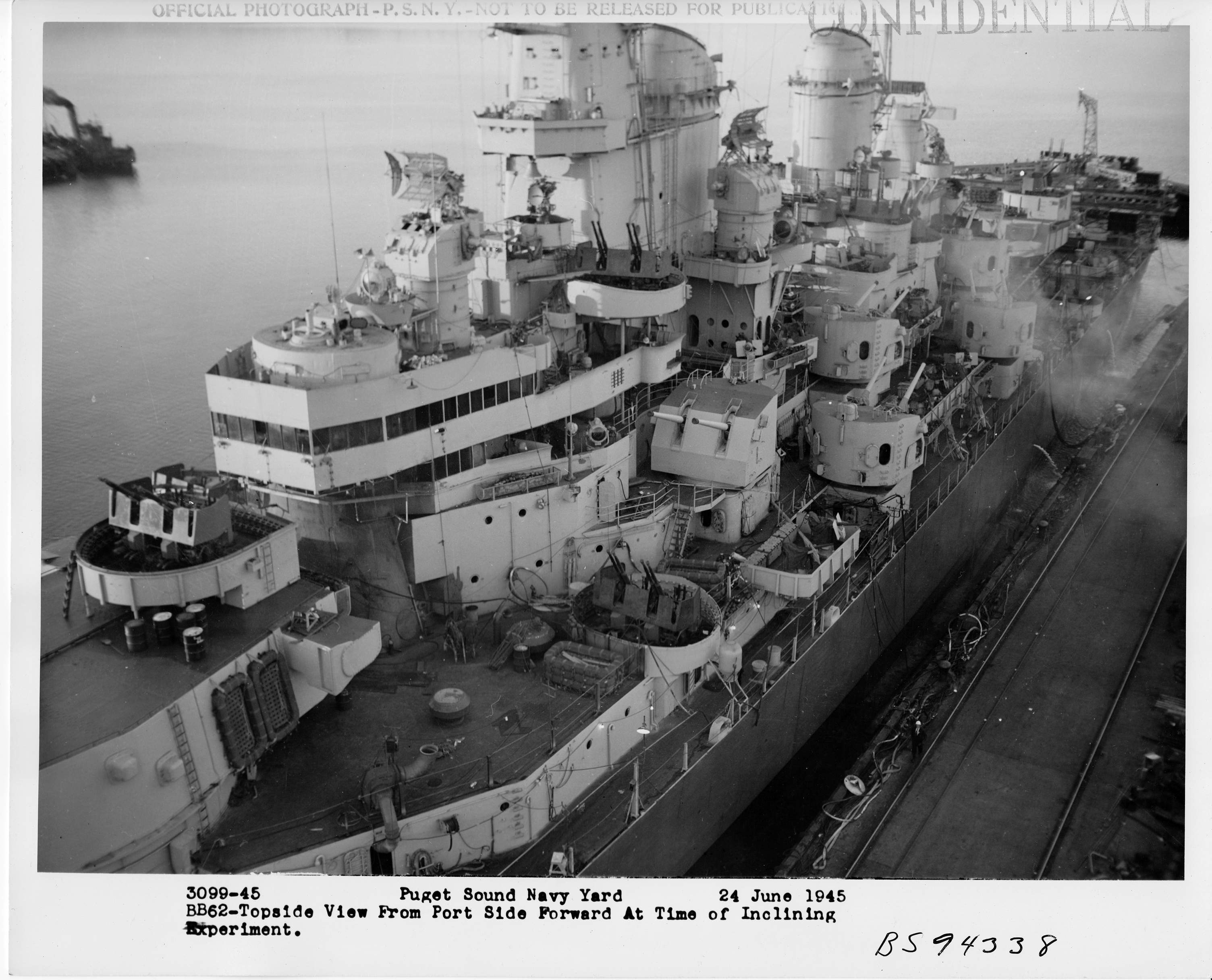
Cliffy B wrote:Question for you guys that I need confirmation on; did any of the Iowas other than the Wisconsin get a Flag Cabin built on the 01 forward directly across from the CO's In Port Cabin during the 1980's refits? From looking at photos and plans the answer "seems" to be no. That being said the official USN plans for Wisky (corrected to 1988) show the original staterooms still there but there is indeed a Flag Cabin. On the exterior there is a WTD leading to a light lock on the port side forward just like on the starboard side that leads into the CO's Cabin. From looking through photos I can't find a similar port side door on any of the other ships. What say you gents? Is this just another little item that makes Wisky unique or am I missing something?
Originally, there were to be no flag facilities. One of the criticisms was that the Iowa return was just to create giant yachts for admirals. The admirals' cabins became the CIC. Later one flag cabins were added on the 01 level.
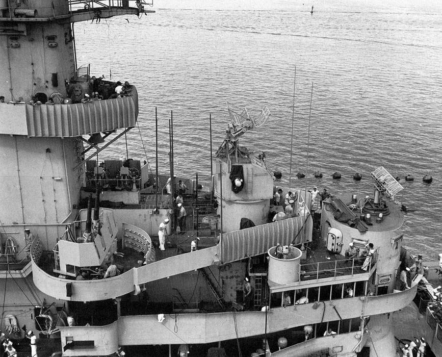
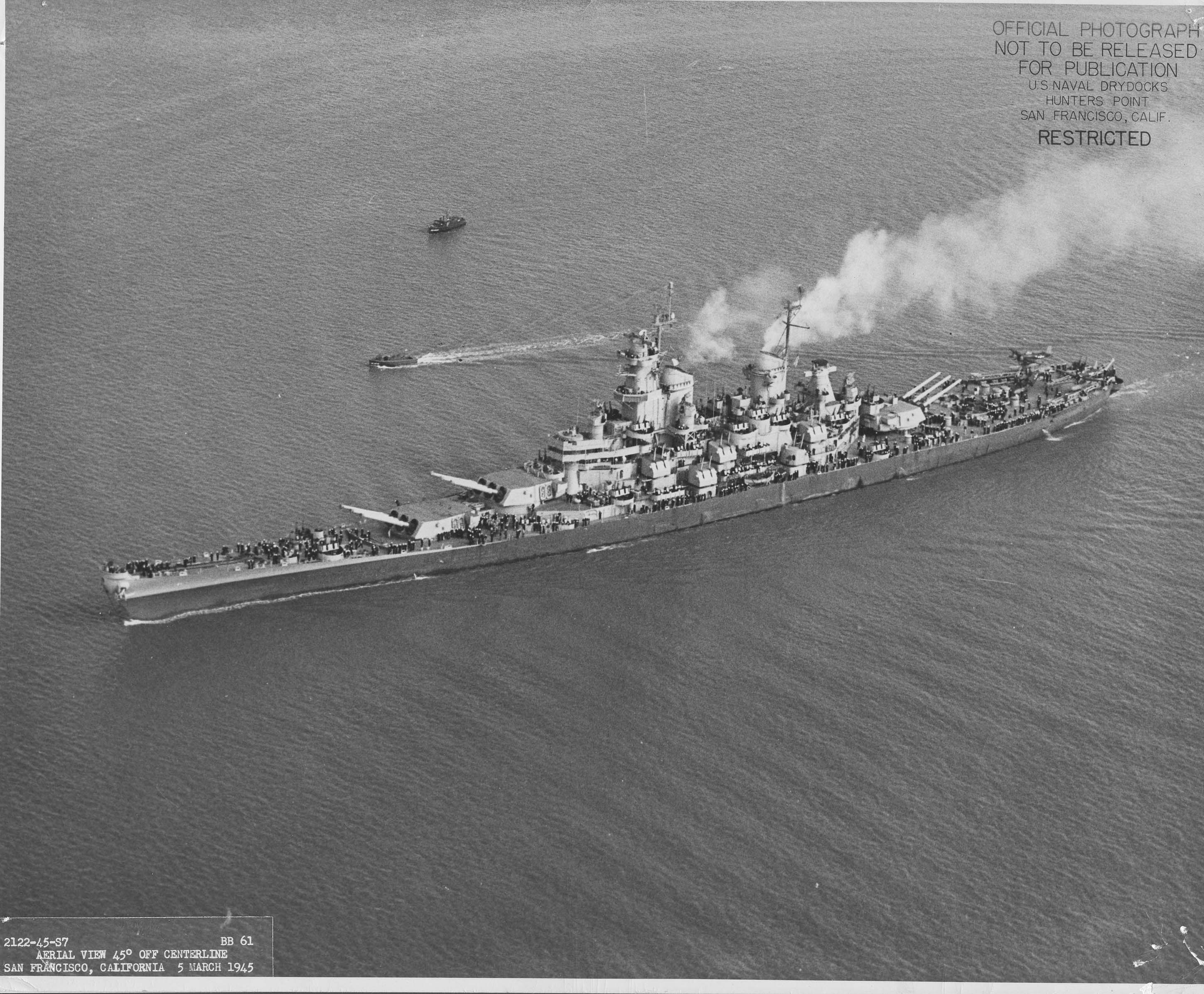
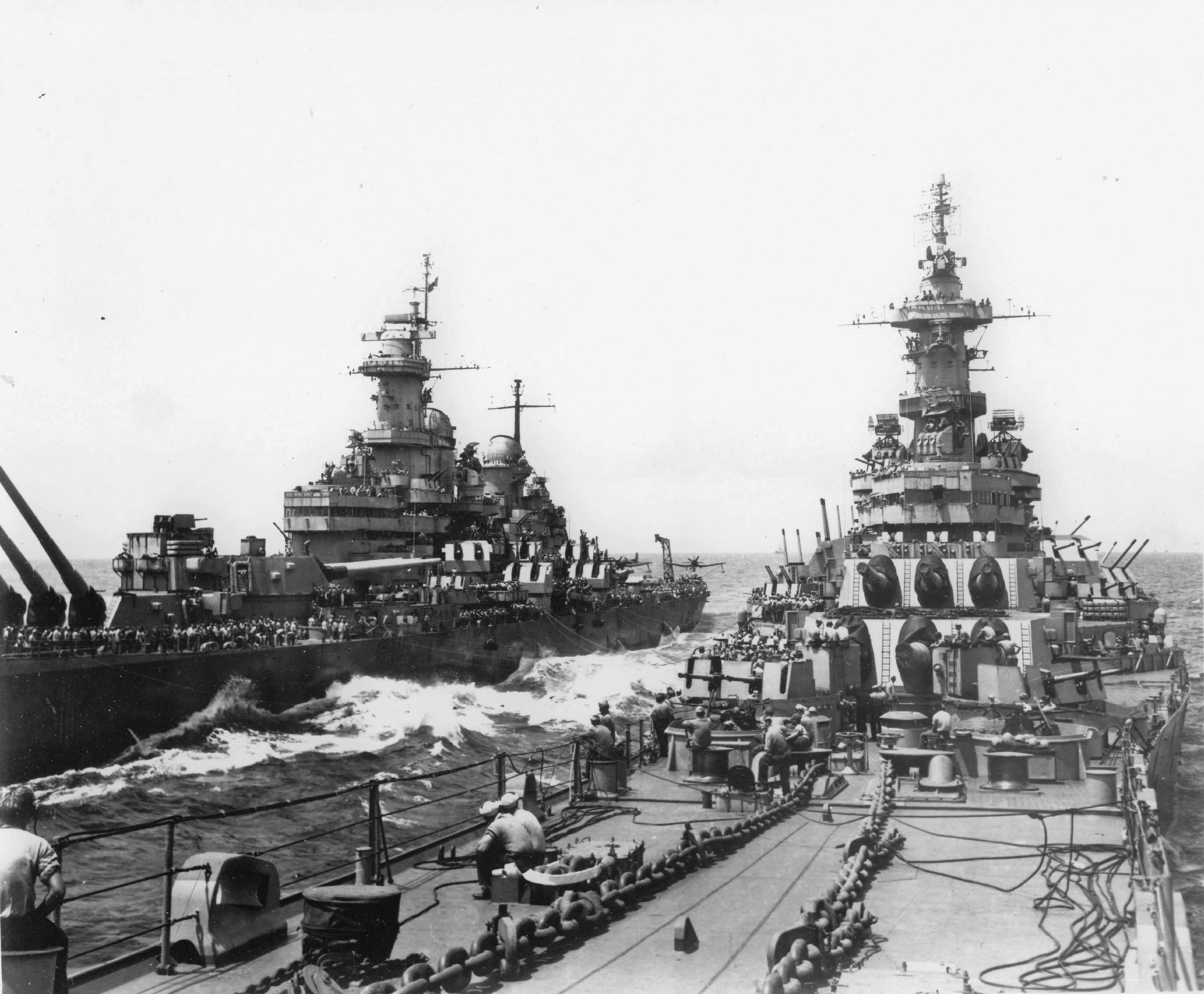
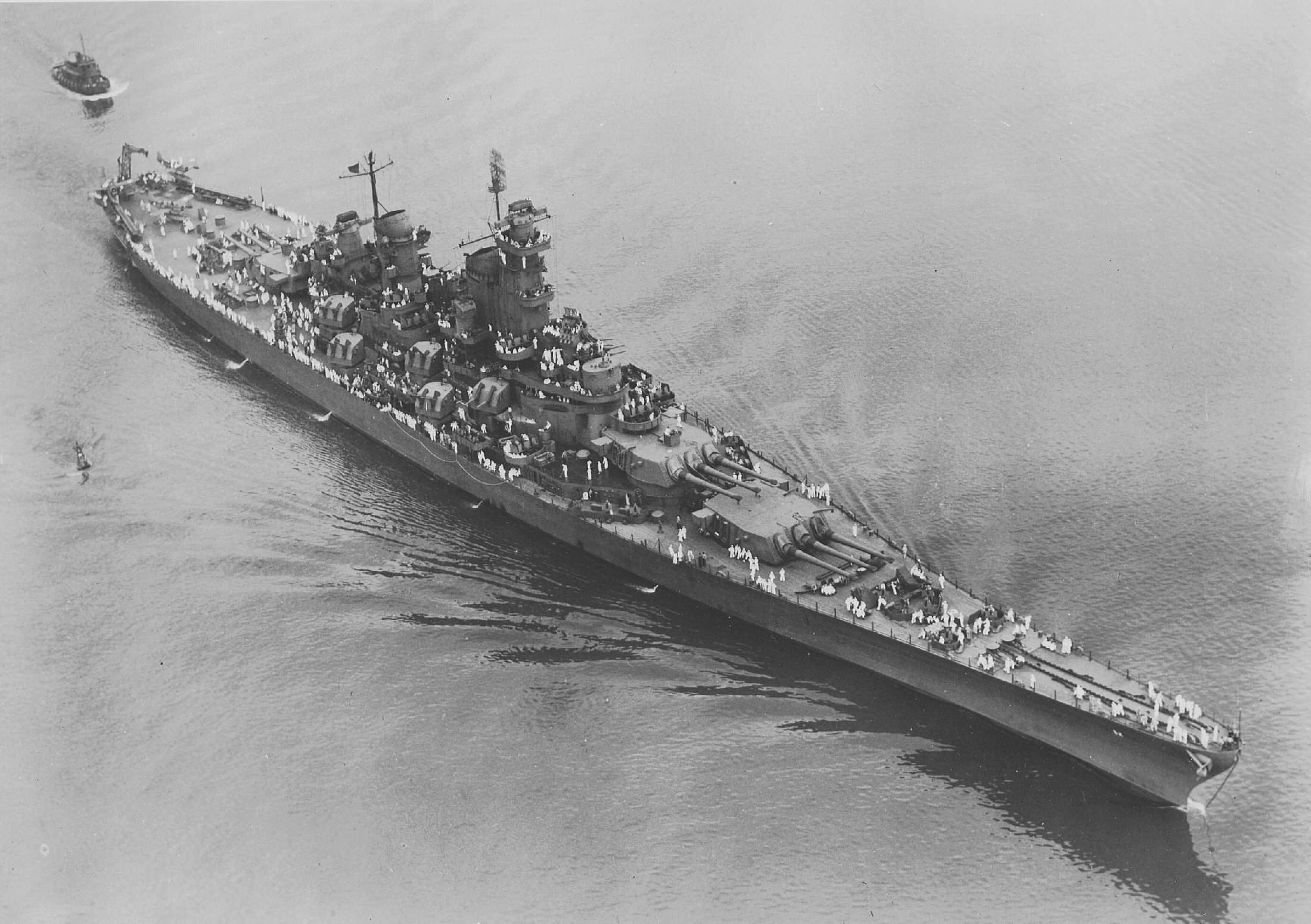
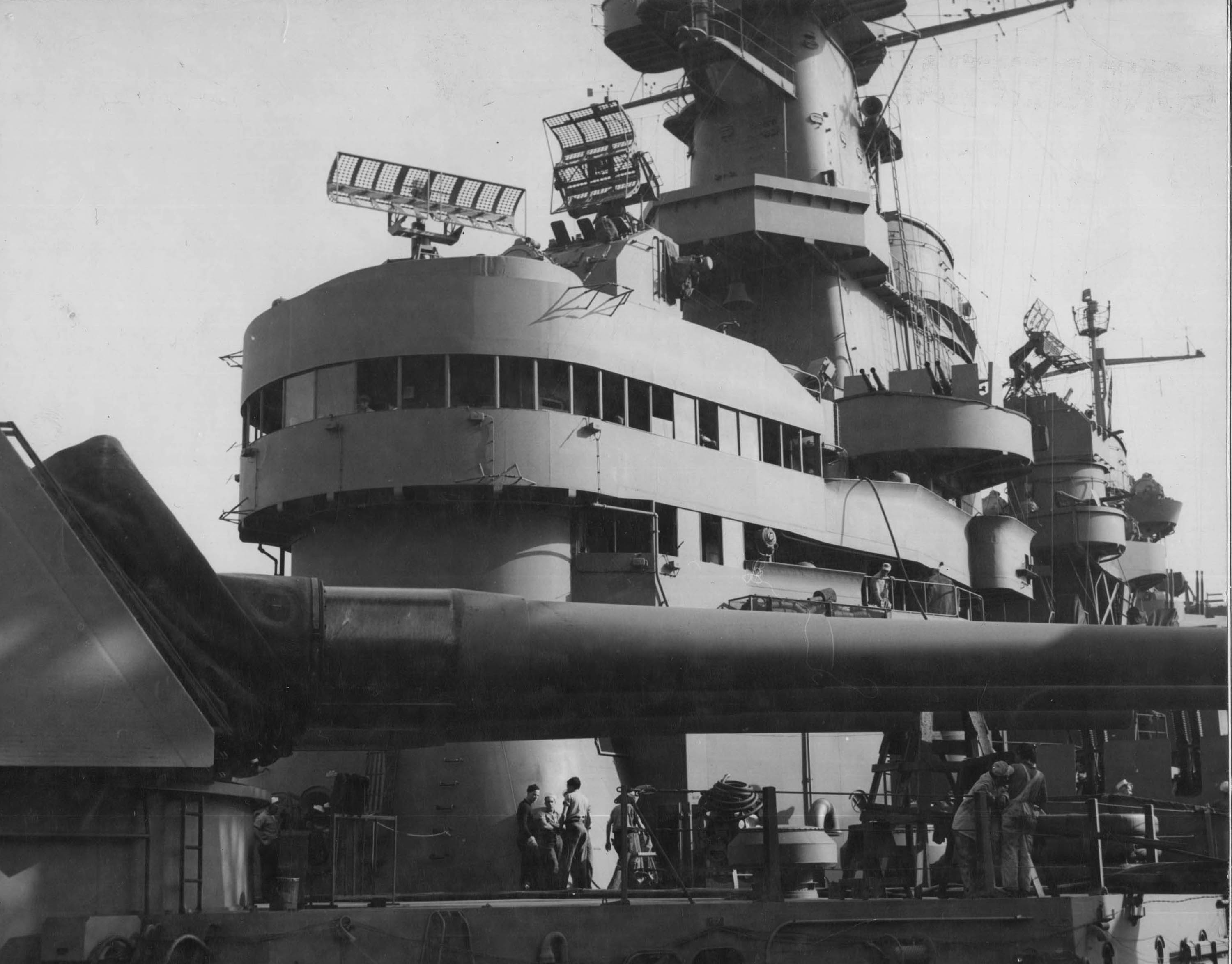
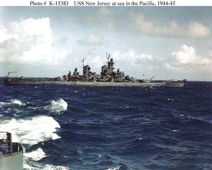
I am debating between building trumpeter's 1/200 Missouri in early to mid 1945 configuration, and building a New Jersey in late 1944 configuration out of trumpeter's 1/200 Iowa kit. Trumpeter's Iowa kit seem to be an early configuration with a naked conning tower. When did the New Jersey get the roof and windows for the circular walkway around the armored conning tower, and when did that get converted into a square enclosed bridge? Did New Jersey have the round roof and windows for the walkway during Leyte? I seem to recall New Jersey having some sort of enclosed bridge when she ploughed through helsey's typhoon.
Does trumpeter capture the differences between the shape of main gunnery directors of Iowa and Missouri?
Assessing the impact of new area rug under modeling table.
When did the New Jersey get the roof and windows for the circular walkway around the armored conning tower, and when did that get converted into a square enclosed bridge? Did New Jersey have the round roof and windows for the walkway during Leyte? I seem to recall New Jersey having some sort of enclosed bridge when she ploughed through helsey's typhoon.
Does trumpeter capture the differences between the shape of main gunnery directors of Iowa and Missouri?
Chuck,
Once again, go to NavSource and under the IOWA class battleship photos (NEW JERSEY), you'll find several photos with dates on the bridge changes to NEW JERSEY.
As for question 2, NO - Trumpeter does not make the Mk. 37 F.C. Directors in their two configurations, only one - the one that is common to NEW JERSEY and MISSOURI. That would require scratchbuilding the IOWA/WISCONSIN later configuration (with the raised overhead).
Hope this helps,
HMS III
Mocksville, NC
BB62 vet 68-69
Builder's yard:
USS STODDARD (DD-566) 66-68 1:144, Various Lg Scale FC Directors Finished:
USS NEW JERSEY (BB-62) 67-69 1:200
USN Sloop/Ship PEACOCK (1813) 1:48
ROYAL CAROLINE (1748) 1:47
AVS (1768) 1:48
The Iowa and New Jersey were built and commissioned with an open bridge.
During the shakedown cruise they found that that bridge didn't work well for air defense and designed bridges to improve that.
She was commissioned in Measure 21 paint scheme and carried it though the entire war.
They changed it to the Measure 22 paint scheme was she was overhauled at Puget Sound.
She didn't make it back to the war zone before the war ended but did make it to Japan in December of 1945 http://www.navsource.org/archives/01/016246.jpg
chuck wrote:I am debating between building trumpeter's 1/200 Missouri in early to mid 1945 configuration, and building a New Jersey in late 1944 configuration out of trumpeter's 1/200 Iowa kit. Trumpeter's Iowa kit seem to be an early configuration with a naked conning tower. When did the New Jersey get the roof and windows for the circular walkway around the armored conning tower, and when did that get converted into a square enclosed bridge? Did New Jersey have the round roof and windows for the walkway during Leyte? I seem to recall New Jersey having some sort of enclosed bridge when she ploughed through helsey's typhoon.
Does trumpeter capture the differences between the shape of main gunnery directors of Iowa and Missouri?
I picked up a 1/200 Iowa kit the other day and already have a 'Mo. They are virtually identical kits except for the bridge and radar. I haven't done a proper survey but it looks like there are lots of small errors such as the bow 20mm gun tub, porthole and doorway locations, piping and so forth that are wrong for the Iowa.
Jason, can you post a picture of the main battery directors and the secondary battery directors.
Those would be different than Missouri and Wiscinsin's for the Iowa and New Jersey.
One of the other differences would be the air defense platform on top of the fire control tower.
I've been wondering about those items and if it's worth picking up the Iowa kit.
You had to rework the Mk38 directors on your model? Since my scratch built ones were the same as the ones I built for my CB1 I didn't have that issue. In other words just lucked out! More interesting information. Looking fwd to seeing some builds of the early bare coning tower ships which share that mean purposeful "Battleship" look of the Sodak's.
Very Nice and enough to keep you busy for a long time! I have indelible memories of Indiana in dark gray broodiness swinging at a buoy in Sinclair Inlet.