Wandered about a used book store in Bellingham Wa today and came across Stillwell's Battleship NJ which at $20 was nicely priced. However I already have that book... I do come across a rare gem now and then.
Looking fwd to seeing progress on the various ships (I should talk).
Cheers from the peanut gallery! T
Calling all Iowa-class (BB-61) fans
Moderators: BB62vet, MartinJQuinn, Timmy C, Gernot, Olaf Held, Dan K, HMAS, ModelMonkey
-
chuck

- Posts: 3384
- Joined: Mon Jan 10, 2005 1:21 pm
- Location: equidistant to everywhere
Re: Calling all USS Iowa class fans
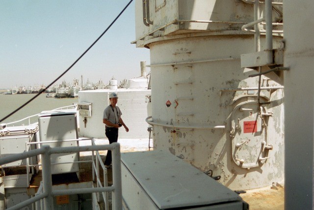
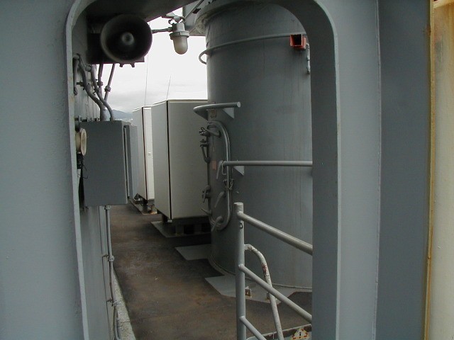
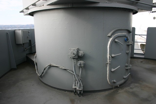
Thanks, James. That's exactly what I needed.James M wrote:Chuck, there is an access hatch on the rear MK37 director foundation and it is at a different height.
Forward director (Iowa):
Midship director:(Missouri)
Aft director (Iowa):
James
Assessing the impact of new area rug under modeling table.
-
James M

- Posts: 252
- Joined: Fri Apr 01, 2005 11:30 pm
- Location: Fullerton, CA
Re: Calling all USS Iowa class fans
Found the information about the WWII draft marks and boot topping. As close to fact as I can come up with.
This is from the Bu Ships plan 353608 / 8/18/41 / corrected working plan 5/15/43
Navy Yard, New York Plan BB616-2806AF
Design Water Line (DWL) 34' 9 1/4"
Bow: Upper line of boot topping: 17" above DWL
Lower line of boot topping: 5' 6 1/2" below DWL
Stern: Upper line of boot topping: 17" above DWL
Lower line of boot topping: 12 1/2" below DWL
Bow = Upper line of boot topping 36' 2 1/2" from keel / total height: 6' 10 3/4"
Stern = Upper line of boot topping 36' 2 1/2" from keel / total height: 2' 4 3/4"
(The upper line of the boot topping is parallel with the DWL/keel)
I haven't located the modernized version plan to know if there is any difference. If needed I can find out about it.
James
This is from the Bu Ships plan 353608 / 8/18/41 / corrected working plan 5/15/43
Navy Yard, New York Plan BB616-2806AF
Design Water Line (DWL) 34' 9 1/4"
Bow: Upper line of boot topping: 17" above DWL
Lower line of boot topping: 5' 6 1/2" below DWL
Stern: Upper line of boot topping: 17" above DWL
Lower line of boot topping: 12 1/2" below DWL
Bow = Upper line of boot topping 36' 2 1/2" from keel / total height: 6' 10 3/4"
Stern = Upper line of boot topping 36' 2 1/2" from keel / total height: 2' 4 3/4"
(The upper line of the boot topping is parallel with the DWL/keel)
I haven't located the modernized version plan to know if there is any difference. If needed I can find out about it.
James
Last edited by James M on Sun Feb 07, 2016 3:57 pm, edited 1 time in total.
-
mconnelley
- Posts: 252
- Joined: Sun Feb 07, 2010 8:13 pm
Re: Calling all USS Iowa class fans
Randy M:
I am very interested in your 3D printed solution to the Missouri's hull issue. I have access to a 3D printer at work. Would you be willing to share the gcode (or similar) file? Our 3D printer can print within a cylinder 10" in diameter and 10" tall. Do your parts fit within that envelope? Or can I buy the parts from you? Thank you.
Cheers
Mike Connelley
I am very interested in your 3D printed solution to the Missouri's hull issue. I have access to a 3D printer at work. Would you be willing to share the gcode (or similar) file? Our 3D printer can print within a cylinder 10" in diameter and 10" tall. Do your parts fit within that envelope? Or can I buy the parts from you? Thank you.
Cheers
Mike Connelley
-
Fliger747
- Posts: 5068
- Joined: Wed Jan 02, 2013 1:15 am
Re: Calling all USS Iowa class fans
That indicates a widely varying boot top, much wider at the bow than the stern. This would make some sense as much loading draft increases at the bow due to two magazines located forward and one aft. Not sure what the fuel loading scheme was or how the tanks could be trimmed for optimal loading.
Interesting! T
Interesting! T
-
James M
- Posts: 252
- Joined: Fri Apr 01, 2005 11:30 pm
- Location: Fullerton, CA
Re: Calling all USS Iowa class fans
Someone a while ago was asking if the decks were painted when the Iowa went to Tehran.
Navsouce posted these:
http://navsource.org/archives/01/pdf/016105j.pdf
That deck is definitely painted.
James
Navsouce posted these:
http://navsource.org/archives/01/pdf/016105j.pdf
That deck is definitely painted.
James
-
Cliffy B

- Posts: 3125
- Joined: Sun Feb 01, 2009 3:55 pm
- Location: Hawaii
- Contact:
Re: Calling all USS Iowa class fans
Something else to note (it seems) that the tops of the 16" barrels are 5-H and not 20-B in that photo.James M wrote:Someone a while ago was asking if the decks were painted when the Iowa went to Tehran.
Navsouce posted these:
http://navsource.org/archives/01/pdf/016105j.pdf
That deck is definitely painted.
James
Drawing Board:
1/700 Whiff USS Leyte and escorts 1984
1/700 Whiff USN Modernized CAs 1984
1/700 Whiff ASW Showdown - FFs vs SSGN 1984
Slipway:
1/700 Whiff USN ASW Hunter Killer Group Dio 1984
1/700 Whiff USS Leyte and escorts 1984
1/700 Whiff USN Modernized CAs 1984
1/700 Whiff ASW Showdown - FFs vs SSGN 1984
Slipway:
1/700 Whiff USN ASW Hunter Killer Group Dio 1984
-
Channell

- Posts: 2068
- Joined: Mon May 14, 2012 12:18 pm
- Location: Salt Lake City, USA
Re: Calling all USS Iowa class fans
That was me... I got a better copy of one of the pics I posted earlier and came to the same conclusion. Navsource also put up quite a few "new" Iowa pics after she got her first AA weapons improvements and it's pretty obvious her deck wasn't painted even though she otherwise had a MS22 paint scheme, so I can do a bare deck with an open bridge arrangement and still keep a clear conscious.James M wrote:Someone a while ago was asking if the decks were painted when the Iowa went to Tehran.
Navsouce posted these:
http://navsource.org/archives/01/pdf/016105j.pdf
That deck is definitely painted.
James

-Jason Channell
Current Project: 1/200 Bismarck
Current Project: 1/200 Bismarck
-
Cliffy B
- Posts: 3125
- Joined: Sun Feb 01, 2009 3:55 pm
- Location: Hawaii
- Contact:
Re: Calling all USS Iowa class fans
Some of those shot may have been during a post overhaul shakedown period where they had stripped the decks to give them a fresh coat of paint. No idea what the protocol was on that but I know you can't just keep piling on paint. At some point they'd strip and redo it completely and an overhaul is a perfect time to do it, especially one in a friendly port where the camo isn't as needed.
Drawing Board:
1/700 Whiff USS Leyte and escorts 1984
1/700 Whiff USN Modernized CAs 1984
1/700 Whiff ASW Showdown - FFs vs SSGN 1984
Slipway:
1/700 Whiff USN ASW Hunter Killer Group Dio 1984
1/700 Whiff USS Leyte and escorts 1984
1/700 Whiff USN Modernized CAs 1984
1/700 Whiff ASW Showdown - FFs vs SSGN 1984
Slipway:
1/700 Whiff USN ASW Hunter Killer Group Dio 1984
-
Channell
- Posts: 2068
- Joined: Mon May 14, 2012 12:18 pm
- Location: Salt Lake City, USA
Re: Calling all USS Iowa class fans
There are color pics of the Iowa on commissioning day and during shakedown with unpainted decks... All I can say is that it appears to me they were first painted just before the trip to the Tehran conference.Cliffy B wrote:Some of those shot may have been during a post overhaul shakedown period where they had stripped the decks to give them a fresh coat of paint. No idea what the protocol was on that but I know you can't just keep piling on paint. At some point they'd strip and redo it completely and an overhaul is a perfect time to do it, especially one in a friendly port where the camo isn't as needed.
-Jason Channell
Current Project: 1/200 Bismarck
Current Project: 1/200 Bismarck
-
RandyM
- Posts: 337
- Joined: Sat Dec 15, 2007 10:40 pm
- Location: San Diego
Re: Calling all USS Iowa class fans
It's good to know that I can still surprise myself at how dumb I can be at times.
After painting the upper-two tones on the hull, I decided it was time to paint the AF-red on the bottom. I actually had the paint mixed and in my brush before realizing that every single Iowa - even the Missouri - was built with FOUR screws, not two. D'oh!
So I've spent a good amount of time correctly locating the outboard shafts - this is something I should have done in the 3D model but somehow overlooked - and then upgrading the kit parts. The flange on the inboard shaft has been causing me fits, but I think I've almost got it. The outboard strut is as close as I can get without actual builder's drawings, and is to scale per FDD plans and photos. I decided to post a raw in-process photo in case someone sees something really out of whack. I haven't had too much time to work on this lately, but hope to spend most of tomorrow at the bench, so if you see something, please chime in.
To Mike Connelley: I am not willing to part with the native SW files - too much sweat and blood invested. However if the STL files are not reverse-engineer-able that would be fine. The printer I use is also a 10x10x10 and it takes two runs to print all the parts (the overall length of the replaced section is 19.0").
I would also be happy to print a set for you at cost (which is not much - the tray and the raw material only). There are several others in line already, and please note that the current total time to print the parts is three days... and I still need to make some final changes (adding the outboard shaft for instance).
Send me a PM and we can discuss timeline.
Randy

After painting the upper-two tones on the hull, I decided it was time to paint the AF-red on the bottom. I actually had the paint mixed and in my brush before realizing that every single Iowa - even the Missouri - was built with FOUR screws, not two. D'oh!
So I've spent a good amount of time correctly locating the outboard shafts - this is something I should have done in the 3D model but somehow overlooked - and then upgrading the kit parts. The flange on the inboard shaft has been causing me fits, but I think I've almost got it. The outboard strut is as close as I can get without actual builder's drawings, and is to scale per FDD plans and photos. I decided to post a raw in-process photo in case someone sees something really out of whack. I haven't had too much time to work on this lately, but hope to spend most of tomorrow at the bench, so if you see something, please chime in.
To Mike Connelley: I am not willing to part with the native SW files - too much sweat and blood invested. However if the STL files are not reverse-engineer-able that would be fine. The printer I use is also a 10x10x10 and it takes two runs to print all the parts (the overall length of the replaced section is 19.0").
I would also be happy to print a set for you at cost (which is not much - the tray and the raw material only). There are several others in line already, and please note that the current total time to print the parts is three days... and I still need to make some final changes (adding the outboard shaft for instance).
Send me a PM and we can discuss timeline.
Randy
-
chuck
- Posts: 3384
- Joined: Mon Jan 10, 2005 1:21 pm
- Location: equidistant to everywhere
Re: Calling all USS Iowa class fans
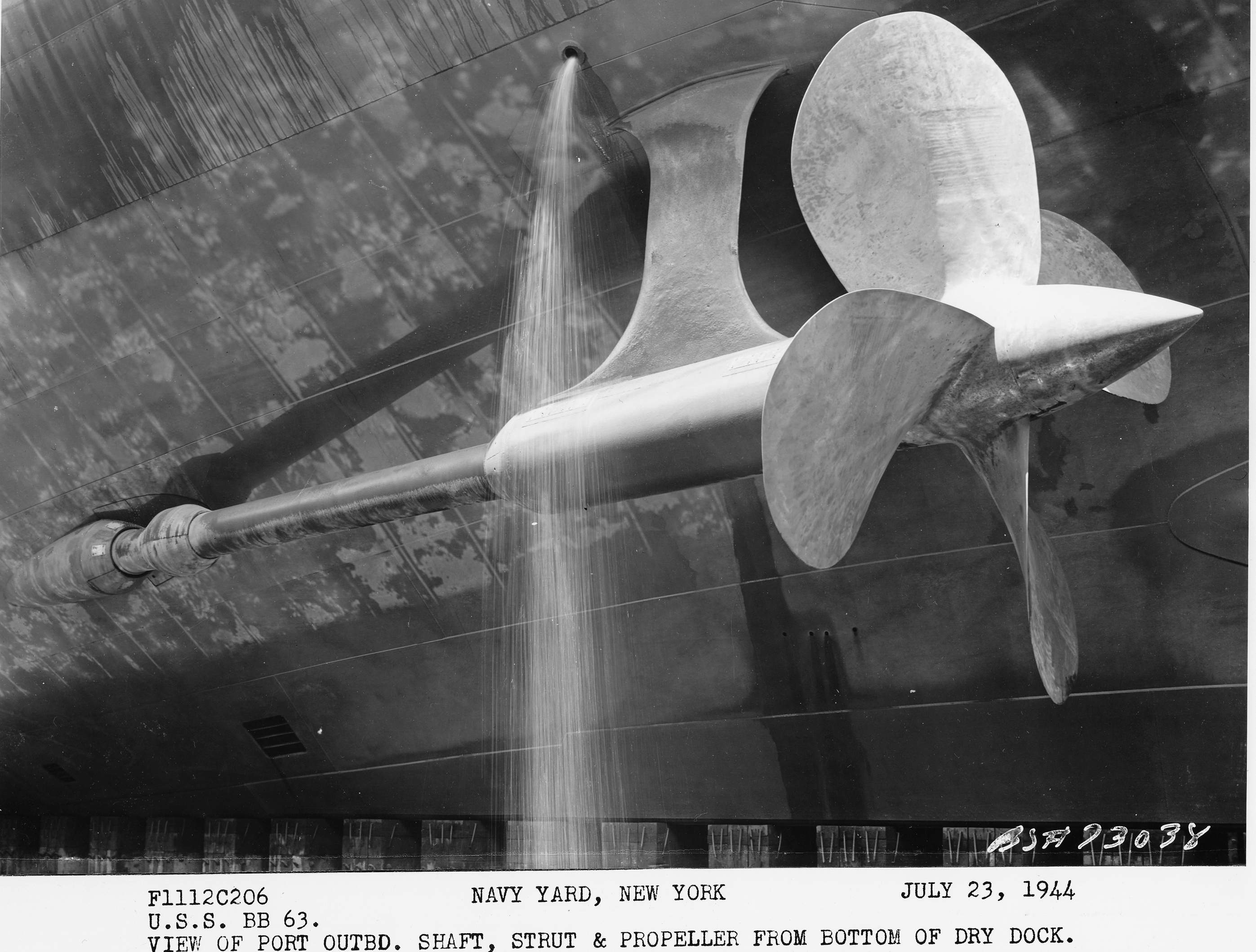
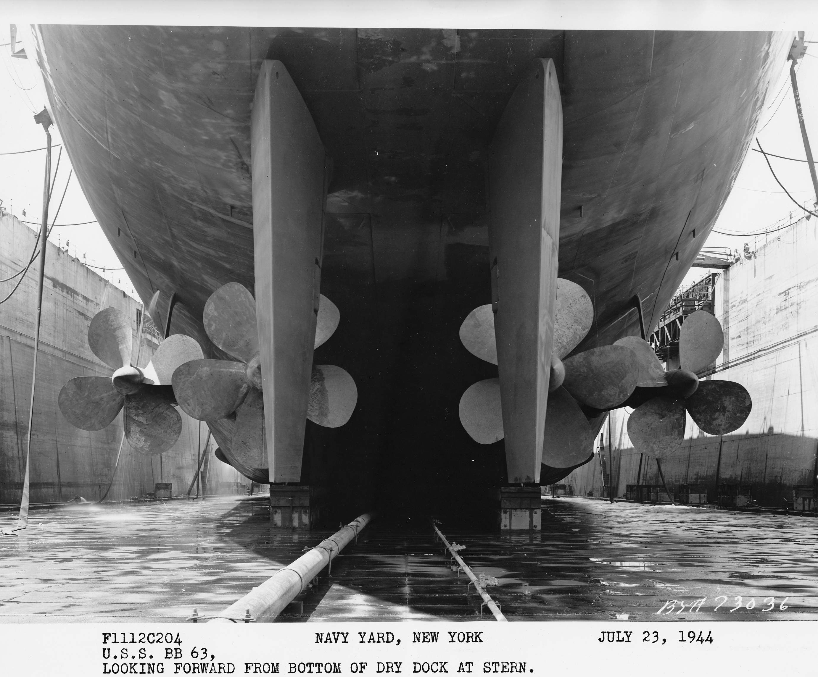
Randy: I think the struts supporting your outboard shafts bend too conspicuously, and the bend is too far from where the struts attach to the hull.
On the missouri, the bend in the strut is hardly noticeable:
http://navsource.org/archives/01/063/016300j.jpg
And is located almost at the point where the strut attaches to the hull:
http://navsource.org/archives/01/063/016332.jpg
On the missouri, the bend in the strut is hardly noticeable:
http://navsource.org/archives/01/063/016300j.jpg
And is located almost at the point where the strut attaches to the hull:
http://navsource.org/archives/01/063/016332.jpg
Last edited by chuck on Sun Jan 11, 2015 12:51 pm, edited 1 time in total.
Assessing the impact of new area rug under modeling table.
-
BB62vet
- Posts: 3163
- Joined: Mon Nov 18, 2013 3:41 pm
- Location: Mocksville, NC
Re: Calling all USS Iowa class fans
Randy,
Well, I missed that "little" detail also - I went back and sure enough, the outboard shaft openings were missing. These things happen - don't beat yourself up too bad, you caught it in time.
I don't know that I have any other photos of any of the IOWAs that would help. I'm not sure what Chuck mentioned above, but here is one shot of BB62 in LBeach (1981) of her port outboard entry point:
Hope this helps!
I hope you didn't lose too much paint in the sprayer!
Hank
Well, I missed that "little" detail also - I went back and sure enough, the outboard shaft openings were missing. These things happen - don't beat yourself up too bad, you caught it in time.
I don't know that I have any other photos of any of the IOWAs that would help. I'm not sure what Chuck mentioned above, but here is one shot of BB62 in LBeach (1981) of her port outboard entry point:
I hope you didn't lose too much paint in the sprayer!
Hank
HMS III
Mocksville, NC
BB62 vet 68-69
Builder's yard:
USS STODDARD (DD-566) 66-68 1:144, Various Lg Scale FC Directors
Finished:
USS NEW JERSEY (BB-62) 67-69 1:200
USN Sloop/Ship PEACOCK (1813) 1:48
ROYAL CAROLINE (1748) 1:47
AVS (1768) 1:48
Mocksville, NC
BB62 vet 68-69
Builder's yard:
USS STODDARD (DD-566) 66-68 1:144, Various Lg Scale FC Directors
Finished:
USS NEW JERSEY (BB-62) 67-69 1:200
USN Sloop/Ship PEACOCK (1813) 1:48
ROYAL CAROLINE (1748) 1:47
AVS (1768) 1:48
-
Fliger747
- Posts: 5068
- Joined: Wed Jan 02, 2013 1:15 am
Re: Calling all USS Iowa class fans
Randy:
Looking at the photo on the previous page of this thread there is no curve in the strut supports and I cannot imagine why there would be one. These continue fairly deep into the hull structure. Hey, don't feel bad about the shafts, my outboards were located and installed long after the hull was otherwise finished. Yours look good of styrene, I did mine out of brass with the original idea of RC. However after getting overboard in small fragile detailing I decided against it.
Regards. Tom
Looking at the photo on the previous page of this thread there is no curve in the strut supports and I cannot imagine why there would be one. These continue fairly deep into the hull structure. Hey, don't feel bad about the shafts, my outboards were located and installed long after the hull was otherwise finished. Yours look good of styrene, I did mine out of brass with the original idea of RC. However after getting overboard in small fragile detailing I decided against it.
Regards. Tom
-
James M
- Posts: 252
- Joined: Fri Apr 01, 2005 11:30 pm
- Location: Fullerton, CA
Re: Calling all USS Iowa class fans
There is a slight bend in the outboard arm.
The curve is there so the arm attaches to the foundation at almost a 90 deg angle. Stronger attachment and less resistant to cracking.

James
The curve is there so the arm attaches to the foundation at almost a 90 deg angle. Stronger attachment and less resistant to cracking.
James
-
RandyM
- Posts: 337
- Joined: Sat Dec 15, 2007 10:40 pm
- Location: San Diego
Re: Calling all USS Iowa class fans
After studying all the photos at my disposal, here is what I came up with. Both strut supports have an identifiable angle between the hull and the strut bushing - most likely for the purpose as stated by James, although I always thought a triangle was stronger. I suppose this arrangement allows for more symmetric flexing under off-axis loads(does a propeller shaft even flex side to side? intuitively is seems that it must...)???
Anyway, here's round two. I'd hoped to get (much) more bench time today but it just wasn't meant to be. As always, point out glaring deficiencies. Heck, when I was building my Boston a kind soul pointed out that I had installed the #2 barbette upside down...
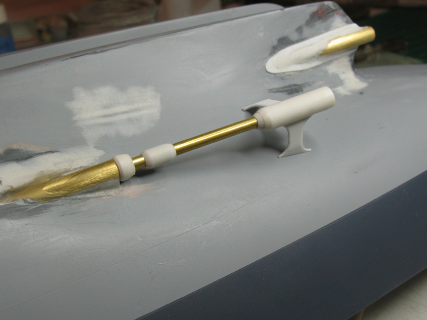
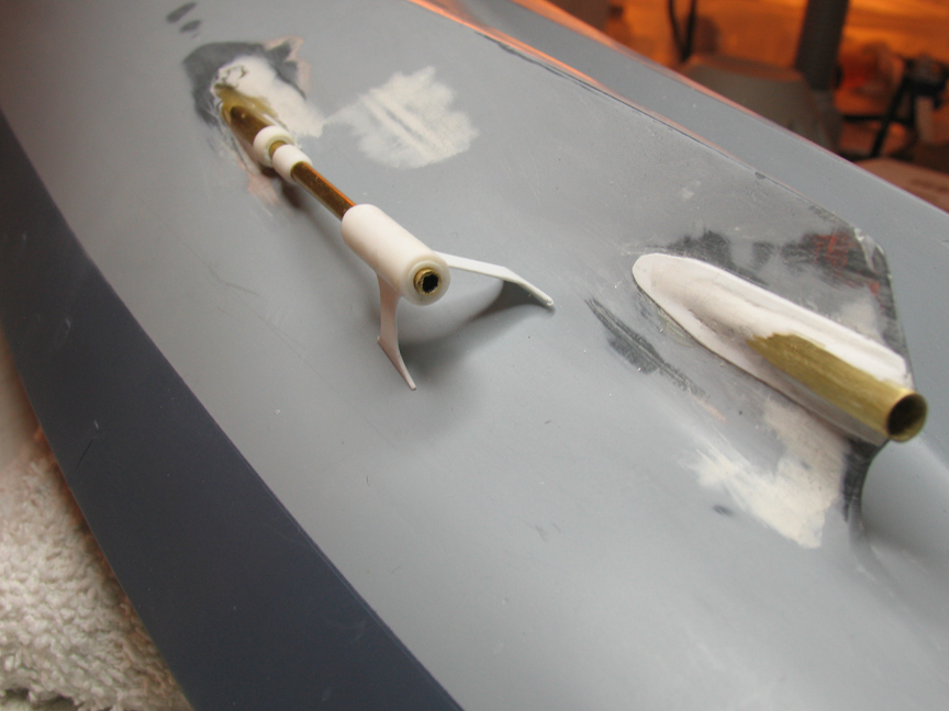
Anyway, here's round two. I'd hoped to get (much) more bench time today but it just wasn't meant to be. As always, point out glaring deficiencies. Heck, when I was building my Boston a kind soul pointed out that I had installed the #2 barbette upside down...
-
Fliger747
- Posts: 5068
- Joined: Wed Jan 02, 2013 1:15 am
Re: Calling all USS Iowa class fans
Interesting photo! I would be surprised if the strut were attached to the shell plating as it's major means of support. I need to re read the detailed documents on the loss of KG-V even though British practice might vary, as this area was critical in her loss.
Too late to change mine, even slightly as they do carry into the model's hull for strength! There is an interesting slanting strake slanting across the shell plating, forward of the outboard props in some photos and not others. Any info on this, it's purpose and possible date of use?
T
Too late to change mine, even slightly as they do carry into the model's hull for strength! There is an interesting slanting strake slanting across the shell plating, forward of the outboard props in some photos and not others. Any info on this, it's purpose and possible date of use?
T
-
chuck
- Posts: 3384
- Joined: Mon Jan 10, 2005 1:21 pm
- Location: equidistant to everywhere
Re: Calling all USS Iowa class fans
Randy:
Looking at the pictures of the real ship and the picture of the model I get the impression your outboard shaft is too close to the hull in the vertical dimension at the point of support struts. It may be the angle, but It looks to me like the outboard strut should be significantly longer compared the diameter of the shaft tube the struts supports than in the model. In fact it looks to me like the outboard and inboard struts on the real ship are close to the same lengths.
Looking at the pictures of the real ship and the picture of the model I get the impression your outboard shaft is too close to the hull in the vertical dimension at the point of support struts. It may be the angle, but It looks to me like the outboard strut should be significantly longer compared the diameter of the shaft tube the struts supports than in the model. In fact it looks to me like the outboard and inboard struts on the real ship are close to the same lengths.
Assessing the impact of new area rug under modeling table.
-
Channell
- Posts: 2068
- Joined: Mon May 14, 2012 12:18 pm
- Location: Salt Lake City, USA
Re: Calling all USS Iowa class fans
What is the big bulb shaped thing on the outboard propshafts anyway? A balancing weight? Some kind of armor protection?
-Jason Channell
Current Project: 1/200 Bismarck
Current Project: 1/200 Bismarck
-
Fliger747
- Posts: 5068
- Joined: Wed Jan 02, 2013 1:15 am
Re: Calling all USS Iowa class fans
Perhaps a coupling or for dynamic balancing? Attached a photo of the very nice John Haynes model in the wardroom of Missouri. Note the hull plating and struts. As is often the practice, he left the shafts in brass, sort of a model bling effect. Props of course are not brass either, but an effect we often live with, a convention if you will. His plating etc subtle and well executed. He also dd all the padeyes along the bow overhang, an advantage of working with a larger model.