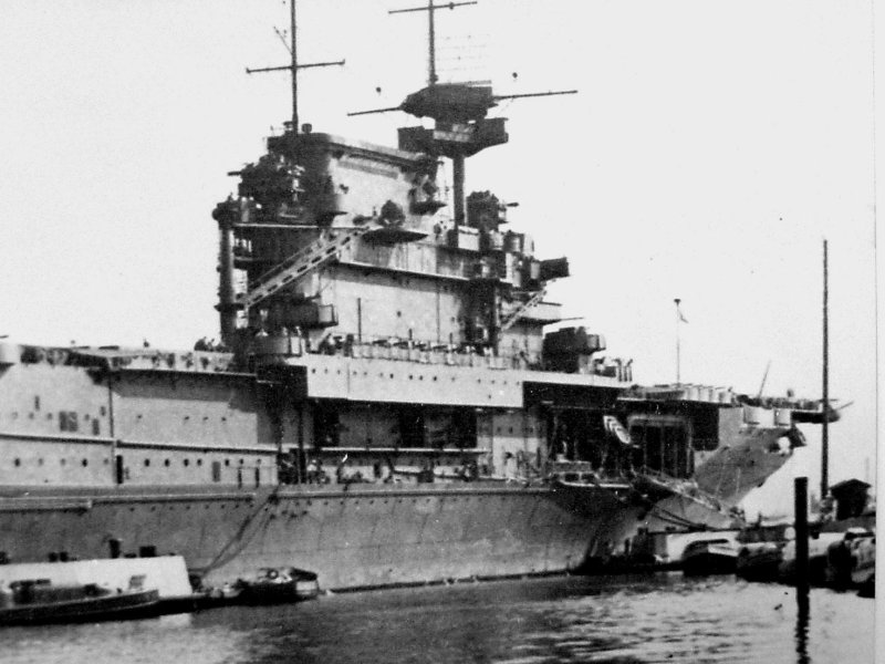
The FSM model is not correct regarding the funnel notch. There is a bulkhead at the rear, and the actual funnel tubes are not visible. There are some steam fittings and pipes in that notch for the steam whistles, horns and siren that are mounted over it on the funnel rim. The Builder's Model is 1/48 scale. it does not show the pipes and fittings inside the little notch area, though. This is what it should look like. Please click the link as the photo was too big.
As for the catwalks around the top of the funnel, the Merit sample does not have them correctly installed. The foot boards of the catwalk should sit just below the rim of the funnel housing. It is Navsource, so you have to click the link: http://www.navsource.org/archives/02/020546.jpg
Thanks for the information Mike!!!
I had seen the builder pics before but had no way of ascertaining if it was absolutely correct or not concerning the void space in the funnel area so thanks again! Looking at the Merit kit, this looks like it should be a easy fix - just fill in the lower portion. The builders' pic looks a bit more recessed than the kit depicts, so I will have to decide whether to do some surgery or let the upper section remain as is.
TOMLABEL
Kelley
Hi Kelley, yes the recess is deeper than Merit depicted. Also, it does not extend below the compass platform. I checked both an early war and a late war CV-6 shot and confirmed that the recess has a bulkhead at the rear and contains pipes and steam fittings as I described above. very hard to find a good detailed shot of it though. On Hornet the builder eased our burden in this spot. Newport News wisely plated the forward funnel face and enclosed all this.
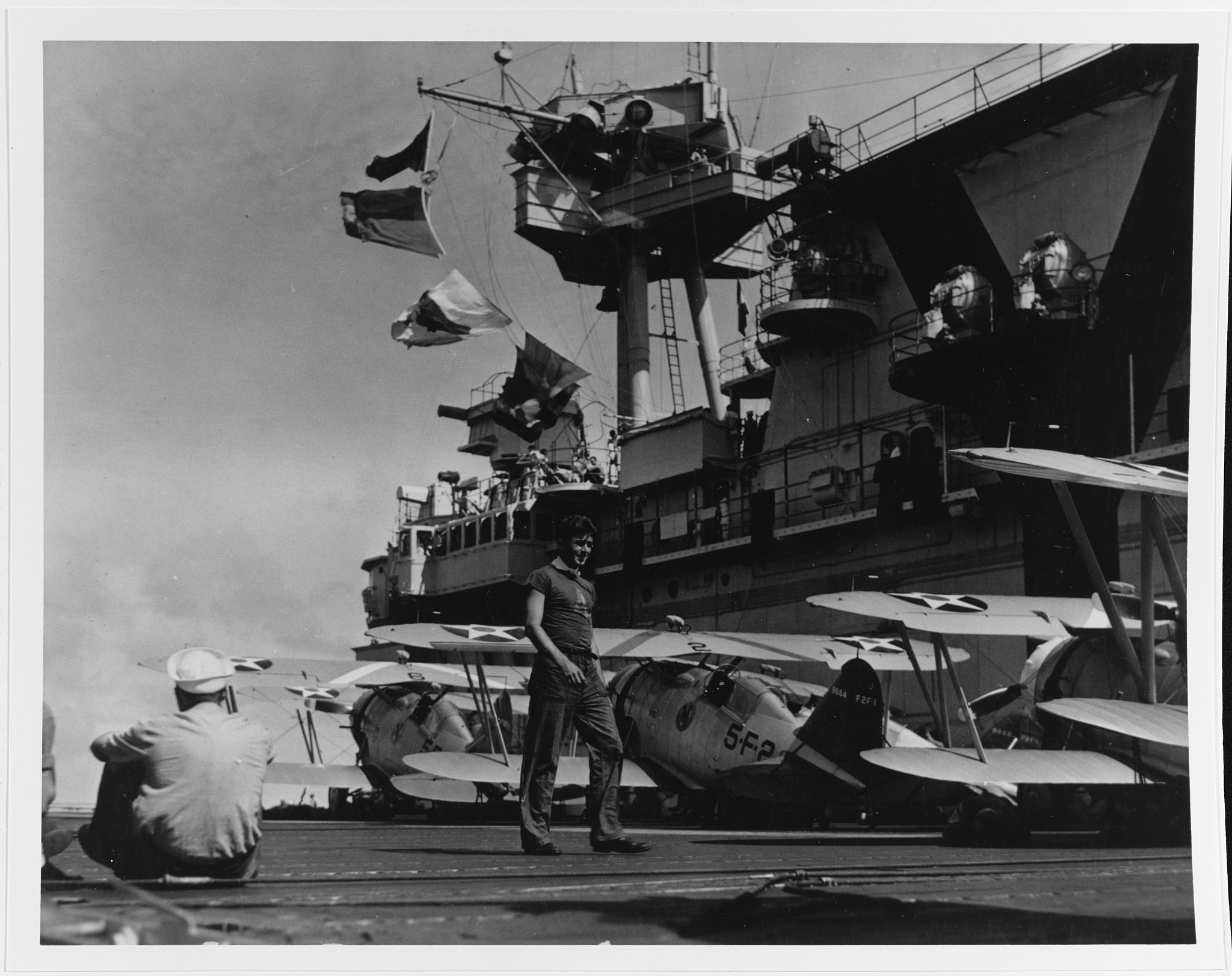
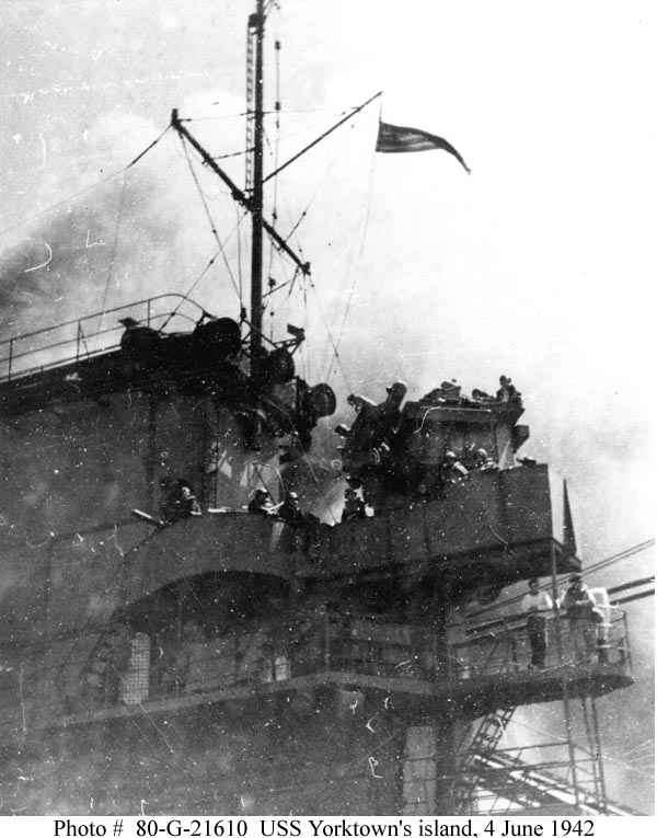
While the rail appears to be higher in the 39 & 42 pics than as launched, it doesn't appear to me that the catwalk itself sits above the top of the funnel. To me it still appears to be below the top of the funnel, with just the rail extending above.
In the 42 pic, you can even see the loudspeakers appear to be attached to the railing.
Does the Merit catwalk installation need modified? It just doesn't look right to me.
Also another quick question on the funnel. Over in a build review on finescale, the builder mentioned that the notch on the front of the stack should actually be open and not a notch, and you should be able to see the uptake through the opening. Is that correct? He actually opened the notch and added a piece of plastic tube to simulate the uptake.
In the 37 pic above, it does appear that it could be open, but in other pics I've looked at, it doesn't seem to be.
Bob
Hi Bob,
I think you are right. The 1937 foot boards are a bit lower than in the 1939 and 1942 shots, along with the railings. They were clearly raised up a little, perhaps at the request of crewmen doing work up there, but the Merit installation is still wrong. The foot boards always remained below the rim of the funnel cap.
Michael Vorrasi wrote:The 1937 foot boards are a bit lower than in the 1939 and 1942 shots, along with the railings.
I couldn't quite decide if they raised the catwalk, or just installed taller rails. In the '37 pic, the rails at the front are taller and then angle down as they move to the sides, so I thought maybe they just raised the rail all the way around. But in the '42 damage pic, the catwalk is clearly just underneath the lip of the funnel cap in the back, so it must have been raised a foot or two.
That will be a pain to fix on the Merit Yorktown, since the prongs on that rectangular frame piece of PE face outward, not inward.
Merit Catwalk Frame.jpg (29.45 KiB) Viewed 2491 times
Only thing I can think of ATM is to glue some small thin pieces of plastic stock to the bottom of the catwalks like the actual supports shown in the pics, and glue them directly to the sides of the funnel.
One other thing I noticed in looking at those pics. All of the catwalks and platforms on the island appear to have perforated steel along the edges. That could be a nice little superdetailing touch that's easy to pull off.
That could be a nice little superdetailing touch that's easy to pull off.
I don't think doing those perforations in scale would be "easy to pull off" at all. However, it could be done so that it matches the character of the hull plating.
Do any of you guys know if the degaussing cables on CV5 angle down and underneath the support bracing for the hangar deck catapult extensions and then back up to right below the hangar level or do they pass through the extension supports somehow?
I've been trying to find a pic that definitely shows this but the best one I can find is the PH drydock photo where it looks like it runs below the supports.
TOMLABEL wrote:I've been trying to find a pic that definitely shows this but the best one I can find is the PH drydock photo where it looks like it runs below the supports.
Yeah, its really tough to tell for sure at this point. The more I look at your picture as well some pics of CV6 when I got home this evening, I'm beginning to believe that the cables ran just under the support braces. In some pics I can make out a slight angle downwards as it approaches the supports, and then a slight angle upwards. But of course, I might just be seeing things.....
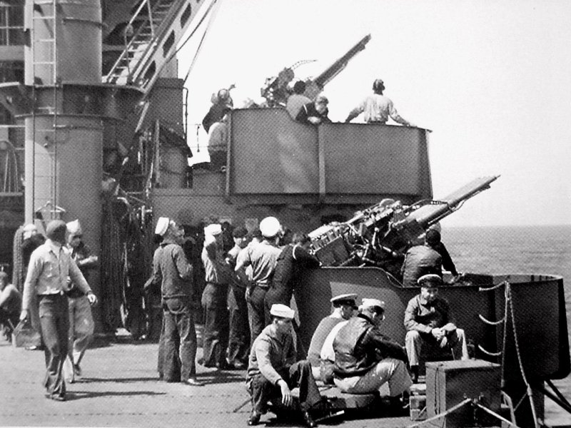
Ok, someone tell me if I'm wrong but it looks very obvious to me the Yorktown's 1.1 tubs did not have the external braces like the Enterprise did so I think the Merit kits tubs will need those removed. One thing I'm not sure about is if the Yorktown's tubs had the small step down in the shields like the Big E's did. I really can't tell for certain.
TOMLABEL wrote:Ok, someone tell me if I'm wrong but it looks very obvious to me the Yorktown's 1.1 tubs did not have the external braces like the Enterprise did so I think the Merit kits tubs will need those removed. One thing I'm not sure about is if the Yorktown's tubs had the small step down in the shields like the Big E's did. I really can't tell for certain.
Thanks!
TOMLABEL
No external braces on CV-5. Her tubs were done at Norfolk, and resembled Hornet's tubs. CV-6 had her 1.1 tubs done at PHNY and look a lot like CV-2's shields. Both of these ships had external braces. Also, CV-6 did not have all circular shaped tubs. However, that changed when she got her enlarged 40mm tubs.
Michael Vorrasi wrote:No external braces on CV-5. Her tubs were done at Norfolk, and resembled Hornet's tubs. CV-6 had her 1.1 tubs done at PHNY and look a lot like CV-2's shields. Both of these ships had external braces. Also, CV-6 did not have all circular shaped tubs. However, that changed when she got her enlarged 40mm tubs.
Hi Mike, thank you and thanks for the additional information on why the differences in the tub design given different yards and time periods - very interesting!!!
However, what do you mean by "CV-6 did not have all circular shaped tubs"? Is this the step down I mentioned or something different?
Michael Vorrasi wrote:No external braces on CV-5. Her tubs were done at Norfolk, and resembled Hornet's tubs. CV-6 had her 1.1 tubs done at PHNY and look a lot like CV-2's shields. Both of these ships had external braces. Also, CV-6 did not have all circular shaped tubs. However, that changed when she got her enlarged 40mm tubs.
Hi Mike, thank you and thanks for the additional information on why the differences in the tub design given different yards and time periods - very interesting!!!
However, what do you mean by "CV-6 did not have all circular shaped tubs"? Is this the step down I mentioned or something different?
Thanks!
TOMLABEL
Hi Kelley,
Not sure what you mean by stepped down. Is it the raised height of the shield along the back side? If so,it is a CV-6 feature only. PHNY had its own shield making patterns, and it was not nearly as neat and professional as Norfolk! Anyway, the 1.1" forward tub on CV-6 was not circular. It followed the edge of the deck and was flat along the port side edge. See this CV-6 photo, the first tub. http://www.navsource.org/archives/02/020694.jpg
In this CV-6 shot, you can see the starboard side of# 1 tub. Numbers 2,3 and 4 were circular, but #3 was not a full tub. The backside (port side) was open to the roof of the clipping room. (see third shot) http://www.navsource.org/archives/02/020645.jpg http://www.navsource.org/archives/02/020657.jpg
Michael Vorrasi wrote:
Not sure what you mean by stepped down. Is it the raised height of the shield along the back side?
Mike, yes, the raised height of the back of the shields was what I was trying to describe. I see what you mean by the more professional looking job that the Norfolk yard did regarding Hornet/Yorktown!! Its kinda hard to imagine why the PHNY tub was designed so differently.
Thanks for the pic links. I don't think I have seen the one with the #3 tub before. It seems strange that the back of the tub wasn't completed, but I guess they had their reasons. The other two pictures I have seen but just totally missed the shape of #1 tub. If you hadn't explained what you were talking about, I probably would have never noticed it!!
Hey-
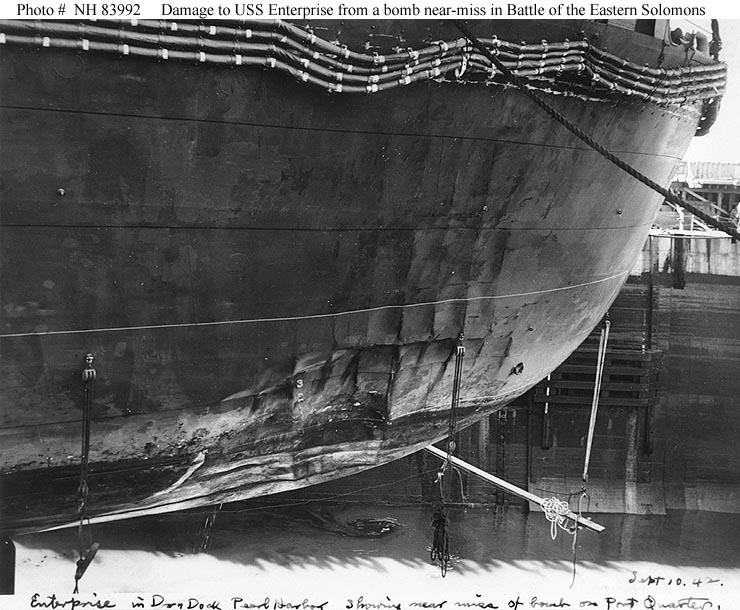
I'd like go back to the degaussing cables for a sec as I need to figure out what to do about them on my Merit kit. From the picture of Yorktown's bow at Pearl After Coral Sea clearly there are three cables side by side on the bow. Each one about 5-6 inches in dia? Do we know for sure how big they were? And from the Ballard wreck photos of the stern, again it's clearly three cables.
But if you scan back along the cables in the above pic they look a bit different amidships, more like a single, maybe larger cable. Maybe they are working on re-installing the cables? But you can more or less see the same thing in the picture of Yorktown leaving Pearl. It hard to see the bow, but amidships it again looks more like a single cable, and if you look above the tugboat's bow and aft of the tugboat you can clearly see the three cables.
So are the cable different amidships than at the bow and stern? Either a single cable, or the three cables bundled together, or running through a pipe instead of flat on the hull? Or it is just tricks of the lighting in the photos. Is there a clear pic of the cables amidships?
I'm starting to work on the Merit Yorktown, in anticipation of Starfighter's BT-5s and pre-war CV-5 decals. Anyone have a recommendation as to which model paint company's Standard Navy Gray 5 I might look for? Also, anyone thought out how to render the mahogany stain on the Merit deck?
Par429 wrote:Hey-
I'd like go back to the degaussing cables for a sec as I need to figure out what to do about them on my Merit kit. From the picture of Yorktown's bow at Pearl After Coral Sea clearly there are three cables side by side on the bow. Each one about 5-6 inches in dia? Do we know for sure how big they were? And from the Ballard wreck photos of the stern, again it's clearly three cables.
But if you scan back along the cables in the above pic they look a bit different amidships, more like a single, maybe larger cable. Maybe they are working on re-installing the cables? But you can more or less see the same thing in the picture of Yorktown leaving Pearl. It hard to see the bow, but amidships it again looks more like a single cable, and if you look above the tugboat's bow and aft of the tugboat you can clearly see the three cables.
So are the cable different amidships than at the bow and stern? Either a single cable, or the three cables bundled together, or running through a pipe instead of flat on the hull? Or it is just tricks of the lighting in the photos. Is there a clear pic of the cables amidships?
Par429 wrote:Hey-
I'd like go back to the degaussing cables for a sec as I need to figure out what to do about them on my Merit kit. From the picture of Yorktown's bow at Pearl After Coral Sea clearly there are three cables side by side on the bow. Each one about 5-6 inches in dia? Do we know for sure how big they were? And from the Ballard wreck photos of the stern, again it's clearly three cables.
But if you scan back along the cables in the above pic they look a bit different amidships, more like a single, maybe larger cable. Maybe they are working on re-installing the cables? But you can more or less see the same thing in the picture of Yorktown leaving Pearl. It hard to see the bow, but amidships it again looks more like a single cable, and if you look above the tugboat's bow and aft of the tugboat you can clearly see the three cables.
So are the cable different amidships than at the bow and stern? Either a single cable, or the three cables bundled together, or running through a pipe instead of flat on the hull? Or it is just tricks of the lighting in the photos. Is there a clear pic of the cables amidships?
To add to what Mike provided, The PH pic shows that there were just 3 cables running from the bow.
It also seems as if the 3 (not 4) cables around the stern of CV5 are continuous as opposed to CV6 based on the photo from Ballard's expedition.
For the rest of my CV5 build, I plan on using the pics of CV6 (like Mike provided links to) to get a general location/number of cables for the port/starboard sides.
TOMLABEL
Attachments
Last edited by TOMLABEL on Mon Oct 26, 2015 8:46 pm, edited 1 time in total.
TOMLABEL wrote:
It also seems as if the 4 cables around the stern of CV5 are continuous as opposed to CV6 based on the photo from Ballard's expedition.
TOMLABEL
Thanks guys-
Tom, I'm not sure what you mean by the above. It looks to me like there are 3 cables around the stern that go as far forward as the forward end of the boat deck or so. Same around the bow, 3 cables that go just aft the catapult sponson. In between there seems to be a single cable. I lightened up the PH picture a little.